LEFA BX-42 User manual

LEFA
INSTRUCTION MANUAL
WOOD CHIPPER
Model : BX-42 & BR-16
ATTENTION
Wood Chipper BX-42 may present dangers during its use.
Read the instruction manual attentively before its use.
LEFA - No.2 HongYang Road,Tian Ning District,
Changzhou, Jinangsu, CHINA
Edition: janvier 2019

2

3
Thank you for having bought the wood chipper of LEFA.
Please follow our recommendations to be fully satisfied with this purchase.
In this manual you will find all the information of use and security.
It is important to follow the instructions for the regular operation of the apparatus and the safety of the
operator.
Please read attentively and carefully all the operations and the cautions concerning the security described in
this manual before the startup of the machine. All operators must read and understand this entire manual,
paying particular attention to safety and operating instructions, prior to using. If there is something in this
manual you don’t understand, ask your superior, or your delaer, to explain it to you.
Most accidents occur because of neglect or carelessness. Keep all helpers and bystanders at least several
hundred feet from an operation rotary wood chipper. Only properly trained people should operate this
machine.
Each LEFA’s machine is equipped with an identification plate where you will find all the data which are
fundamental to verify the accounting between the machine and the tractor and for all order of spare parts.
LEFA wood chipper BX-42 & BR-16 is designed for cutting the woods 10-100mm.
LEFA declines all responsibility for damage caused by the non-reading of the instructions given in this
manual or for any use not in accordance with the destination of the machine or lack of maintenance.

4
SECURITY
Labels of safety and Plate of identification
Read instruction
manual before use or
maintenance
Stop the tractor
engine and remove
the key before
working on the
machine..
Risk of being caught
by the transmission.
Do not approach the
machine and avoid
wearing loose clothes
which could become
entangled in moving
parts
PTO Speed max. :
540 tr/min
MAX
Risk of projections.
To be held apart from
the operating range of
the machine. Make
sure that all the
guards are in their
place during the use..
540 tr/min
Danger of cutting.
To be held apart
from the operating
range of the
machine. Make
sure that all the
guards are in their
place during the
use.
Manufacturer's identification license :
It is strictly prohibited to remove protections of safety, labels of safety and the
plate of identification manufacturer.

5
Safety rules: :
In order to avoid accidents during work, it is necessary to observe the most elementary rules of
prudence:
1. Operator
- The operator should not start the machine if they don’t have all their mental and physical faculties
during assembly, installation, operation, adjustment, maintenant, repairing, removal, or moving the
implement:
Good eyesight and good hearing
Read and study the manual
Be attentive to its and others’ security
Be familiar with the use and maintenance of the machine
It is strictly forbidden to drink alcohol, ingest drugs and other substances that might
affect the use of the machine
- Do not wear loose floating clothing that could be caught by moving parts.
- Wear the appropriate security equipment :
Standardized working gloves
Safety shoes
Helmet
Hearing protection device
Protective glasses
2. Machine
- The coupling must be done only on the points provided for this purpose in accordance with safety
standards.
- Prohibit using the machine as means of transport of people, animals or objects.
- Ensure wood chipper is properly mounted, adjusted and in good operation condition
- Operate only in daylight or good artificial light
- The machine should be in perfect working condition, maintained with original parts.
- Use the cardan shaft recommended by the manufacturer.
- The transmission protectors must be in good condition.
- Check the direction of rotation of the tractor power take-off.
- It is strictly prohibited to make modifications on the machine without authorization of the
manufacturer.
3. Utilization
- Prudence is required during the attachment of the machine to the tractor and during its uncoupling.
- Make sure that the tractor's PTO is not engaged or that the tractor's hydraulic distributor is in the
neutral position.
- The maintenance, the cleaning as well as the adjustments must be made only if the engine of the
tractor is turned off and the ignition key is removed.
- Make sure that no one is in the operating area of the machine.
LEFA disclaims all the responsibilities for damages of nature reason caused by the non-observance of
safety rules and of use.

6
Specifications:
Model
BX-42
BR-16
Power Required
18-35hp
18-35hp
No. of blades
4+1pcs
Rotor Size
600mm(25’’)
Weight
195kgs
235kgs
PTO speed
540/1000 tr/min
Working Efficiency
6-7 m³/h
OPERATION
cap
adjustable
feed hopper
INSTRUCTIONS
Before assembling and using the machine, it is important to read the instructions supplied and to observe the
safety instructions.
The machine should only be used to cut wood and branches into small pieces.
The diameter shouldn’t exceed 100 mm.
The foreign objects, such as the soils, stones, irons, plastics, etc.. shouldn’t be inserted into the machine.

7
Always stop the tractor, disengage PTO, set brake, shut off the tractor engine, remove the ignition key, lower
implement to the ground and allow rotating pieces to come to a complete stop before dismounting the tractor
running.
Never place hands or feet under wood chipper with tractor engine running or before you are sure all motion
has stopped. Stay clear of all moving parts.
TRANSPORT
Comply with state and local laws governing highway safety and movement of farm machinery on public
roads.
The wood chipper is assembled on some support feet to assure a stable position.
Keep alert for uneven terrain, holes, rocks, roots and other hidden hazards. Keep away from drop-offs and
hazards that could cause roll over. Use extreme care and maintain minimum ground speed when transporting
or operating on hillsides, over rough ground and when operating close to ditches or fences.
Be careful and slow and slow down when turning sharp corners and changing direction on slopes. Don’t start
or stop suddenly on slopes.Avoid operation on steep slopes.
OPTIONS :
Support feet
ASSEMBLY OF THE MACHINE
The machine is designed to be mounted on the tractor's three-point hitch or dragged. The length of the
PTO shaft must be adapted to the tractor.
Use a cardan with safety screw
3 POINT LINKAGE
PTO cardan
When the pieces of wood are thrown out of hopper, it causes some dust, so it is recommended to use a guard
to protect.

8
It is dangerous to wear loose clothing that can get into the machine.
Never put your hands, arms or feet into the hopper when the machine is running.
CHECKING BEFORE STARTING THE MACHINE
Check that the machine is placed horizontally and stably
Check that there are no strange objects in the entrance of hopper
Check that all the protections of the PTO shaft are fixed
Check that all protective devices marked with a yellow warning plate have been correctly fixed.
LUBRICATION:
Bearing A
- Lubricate every 8 hours of operation on both bearing A on each side.
- Use EP2 Graisse
OPERATE THE MACHINE WITH THE REMOVED HOPPER OR FEED NEVER
CHUTE
VERIFICATIONS AND REPAIRS
ALWAYS STOP THE MACHINE AND ENSURE THAT THE PTO SHAFT
AREIMMOBILIZED. THEN DISASSEMBLE THE PTO SHAFT.
To ensure a homogeneous insertion, it is important that the insertion cylinder is in perfect situation
and that the cutting knives are set correctly.
We recommend that you sharpen the knives regularly.
This operation must be done by a professional person, in a specialized workshop.

9
REMPLACEMENT OF KNIVES
ALWAYS STOP THE TRACTOR AND WITHDRAW THE KEYS BEFORE REPLACING
OR SHARPENING THE KNIVES
DON’T TOUCH THE EDGE OF KNIVES WITH YOUR FINGERS AND HANDS.
ALWAYS USE THE GLOVES
DISASSEMBLING and RE-ASSEMBLING KNIVES :
ATTENTION :Before the start, always stop the tractor, take off the ignition key, wait for the
transmission to stop and unplug it.
DISASSEMBLY :
- 1 Unscrew Bolt A and remove it
- 2 Turn the Cover B and ensure there is nobody in front
- 3 Unscrew the Bolts and remove them
- 4 Take off the Knife D( Always use some protection gloves to avoid the injury
ASSEMBLY:
- 1 Put the Knife D in place.( Always use protective gloves to avoid the injury)
- 2 Put the Bolts C and tighten them
- 3 Return the Cover B and ensure that there is nobody in front
- 4 Put the Bolts A and tightened them
IT’S RECOMMENDED TO MAKE THESE OPERATIONS BY A PROFESSIONAL
PERSON, IN A SPECIALIZED WORKSHOP.
KNIFE D
BOLT C
BOLT A
COVER B

10
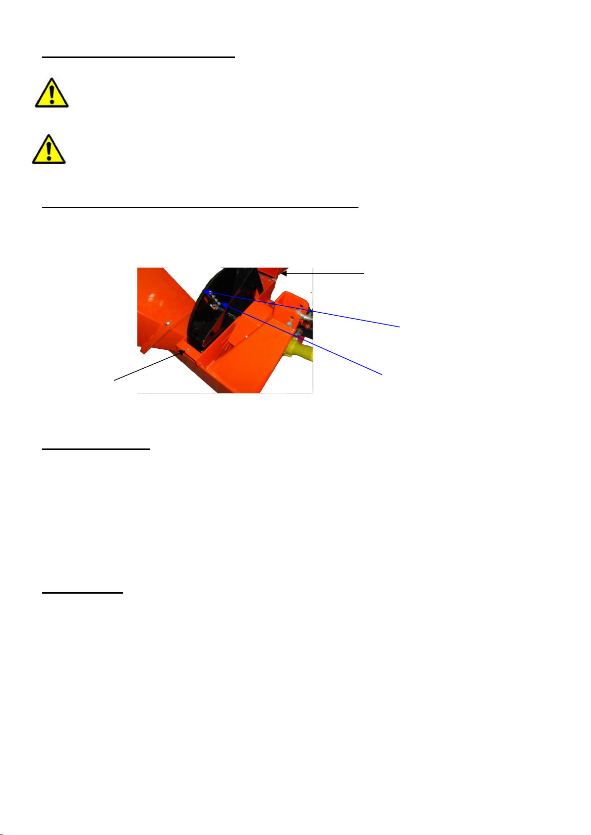
CONNECT THE MACHINE TO TRACTOR:
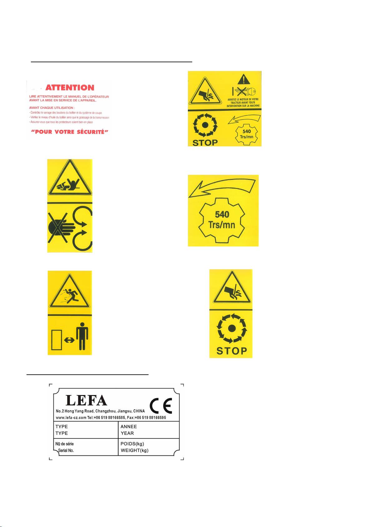
The machine must be connected to the tractor by the PTO operated at 540 t/rpm, with required weight and
power.
During the process of using, adjustment, maintenance, repair or displacement, the operator must use the
appropriate Personal Protection Equipment (PPE).
ATTENTION:
AVOID STATIONING IN FRONT OF THE MACHINE.
AVOID THE PRESENCE OF PEOPLE.
DURING THE ASSEMBLY, THE PTO MUST ALWAYS BE DISENGAGED.
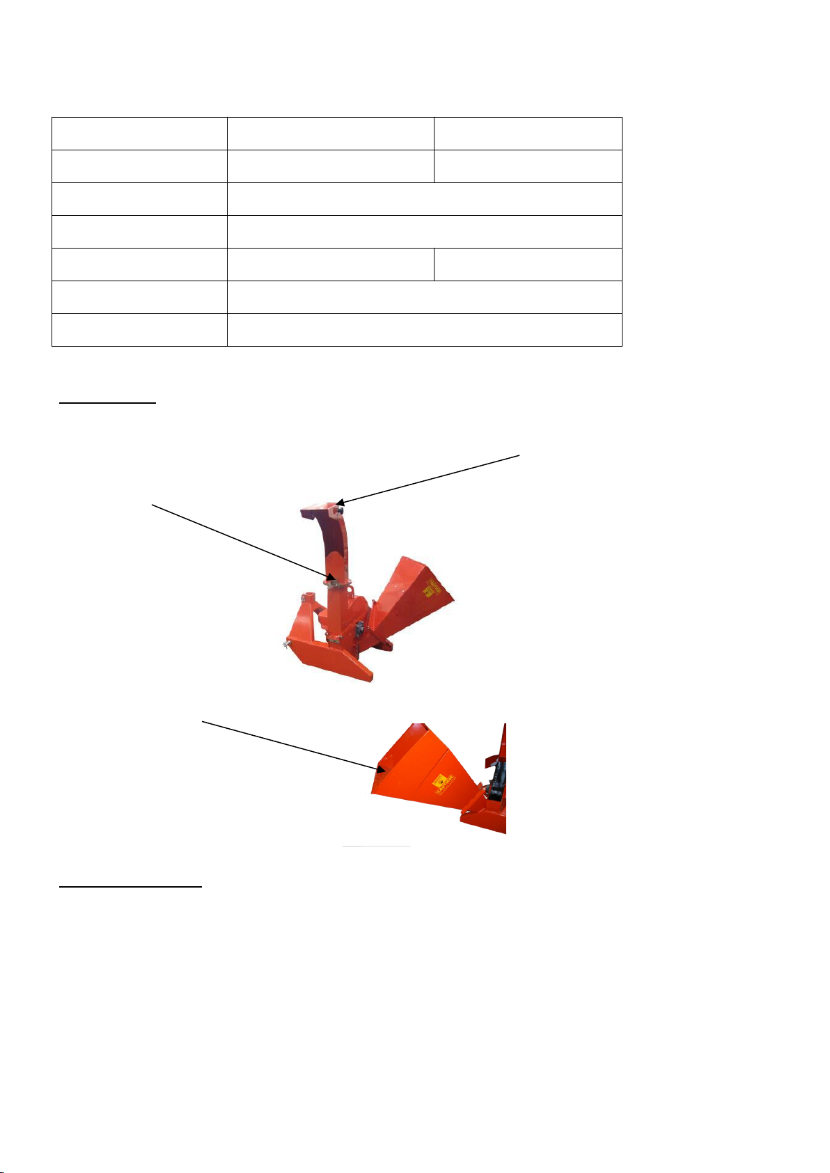
Before assembling the machine, check whether it is laying on the land and paralleled , whether the lubricants
are at the correct level and whether all parts are in perfect condition. Also check whether the tractor is
suitable for carrying the machine. Make sure that the rotations of P.T.O. are the same as the machine. After
these checks, proceed as follows: - brake and switch off the tractor, remove the ignition key and go down; -
adjust the arms of tie rods to prevent any oscillation to the right and to the left of the machine; - Assemble
the cardan shaft and ensure that the bolts are inserted into the slots after checking the length. - apply the
three point linkage. - lift the machine slightly off the ground and raise the support feet.
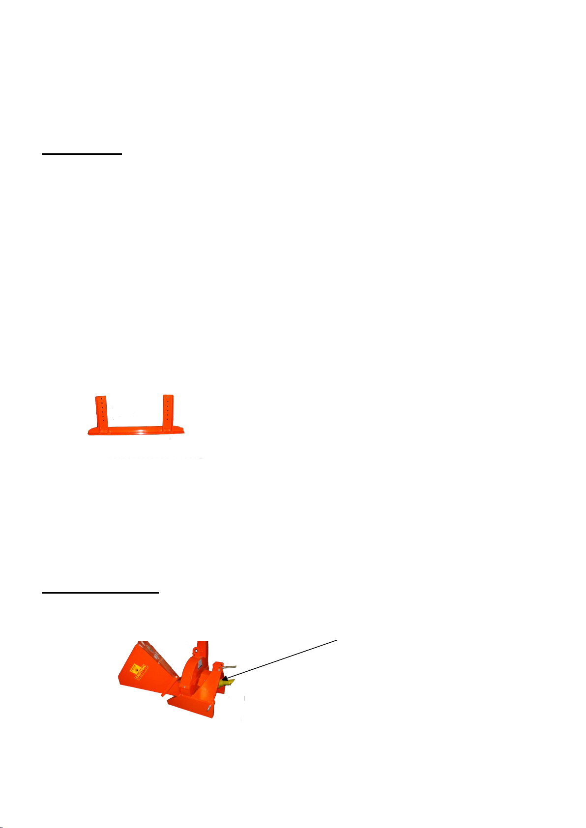
SPECIFICATIONS OF PTO CARDAN :
Insert the cardan shaft onto the spline shaft of the machine until the dowel locks into place.
Don’t use the cardan without protections.
Never extend the cardan
If the machine is connected to tractor for first time, please ensure that:
Under maximum steering conditions, the cardan is not fully closed to avoid damage to the speed
increaser or tractor.
In the case where the cardan is too long, it would be necessary to shorten it by cutting it.
The cardan shaft is the transmission part which drives the machine; it must be adapted to the machine: the
size and length.

11
ATTENTION:
The cardan shaft can cause some situations of risk and danger. Therefore It’s necessary:
- to read and keep the instructions for use.
- use only the cardan shaft supplied with the machine;
- replace worn, broken or missing guards;
- switch off the tractor engine before acting on the cardan shaft.
- do not allow the children or strangers to approach to the machine during the maintenance;
- When the cardan shaft is not used, put it on a support.
- wear adequate clothes (ex: work blues with protections.)
First assembly of the cardan shaft:
Measure the distance K between the PTO grooves, the machine placed on the ground, paralleled and the
speed increaser aligned on the PTO of the tractor: adapt the length of the cardan shaft, the telescopic tubes
allow the ends an interval L between 30 and 40 mm.
IMPORTANT:
THIS OPERATION MUST BE MADE DURING THE FIRST ASSEMBLY AND EVERY TIME
THE MACHINE IS ADAPTED TO OTHER TRACTOR. ATTENTION: AFTER ASSEMBLING
THE CARDAN, FIX THE CHAINS ON BOTH END.
IMPORTANT:
Lubricate the cardan shaft as shown in the instruction manual.
IMPORTANT:
Read the instructions carefully. After having assembled the cardan shaft, make some operation slowly, hinge
the machine to check if the cardan shaft slide freely without brake.
CIRCULTATION ON THE PUBLIC ROAD
In the event that we should drive on a public road, it should be necessary to respect the
Road Rules.
THE TRANSPORT MUST BE EXECUTED WITH MAXIMUM ATTENTION TO
AVOID DANGER TO PERSONS AND VEHICLES WITH PASSENGERS.
Before the transport, check that all parts of the machine are intact and in good
condition.

12
STORAGE :
If the machine is immobilized for long periods of time, store it in a place protected from atmospheric zones
and cover it to prevent damage.
Before the storage, we recommend cleaning thoroughly the entire machine and lubricating all mechanical
parts adequately to prevent rust. Check that the storage temperature is between 0 °C and 50 °C.
Before shutting down the machine for long periods of time, it’s best to proceed as follows:
•remove all possible chippers residues left in the rotor and equipment;
•clean the machine thoroughly;
•carry out a general visual inspection of the machine to detect any possible damage to the structure, identify
any possible deep abrasion of the paint, check that the original safety pictograms are in their positions, and
that they are complete and legible
•Inspect all rotating parts for entangled material.Remove all entangled material.
•Run the machine a few minutes to dry the moisture from inside the machine
•lubricate all the mechanical parts and the tightened pivots;
•Move the feed hopper up and lock
•Touch up all paint nicks and scratches to prevent rusting
•store the machine, if possible, in a covered place on a flat and consistent surface;
•Don’t allow children to play around the stored place
RE-USAGE AFTER A LONG PERIOD OF INACTIVITY:
Before using the machine for the first time, or after a long period of inactivity, it should proceed as follows:
- check that the machine is not damaged;
- check the mechanical parts, which must be in good condition and not rusted;
- check the status of damage of the equipment; carefully lubricate all moving parts;
- check that all guards are correctly positioned, in good condition and intact.
MANUEL UPDATE :
The manufacturer reserves the rights to make any modifications to the machine at any time for technical or
commercial reasons. These modifications do not oblige the manufacturer to have to intervene on the
machines already commercial until then, not to consider this publication inappropriate.
Any possible integrations that the manufacturer deems necessary to be supplied in sequence must be kept
with the manual and considered as an integral part of it.
Spare parts
Repairs and replacements must be done at your Concessionaire.

13
MAINTENANCE :
Check the tightened bolts:
1st time ………………….1 hour
2nd time…………………10 hours
After all times……………25 hours
Lubrication …………………8 hours
Check the damage, knives and fixation ………….10 hours
Make sure there is plenty of ventilation.
A fire extingusher and first-ais kit should be kept readily accessible while performing maintenance on this
equipment
Periodically tighten all bolts , nuts and screws and check that all electrical and fuel connections are properly
secured to ensure unit is in a safe condition
When completing a maintenance or service function, make sure all safety shileds and devices are installed
before placing unit in service
WARRANTY
When deliver the machine, check that the machine has not been damaged during transport and that its
accessories are complete.
CONDITIONS OF WARRANTY
- LEFA new equipment is warranted against defects in materials and construction defect for one year from
the date of delivery. At the end of that period , the guarantee legally ceases. In any case, transportation and
labor costs will be charged to the customer.
- The warranty does not include the payment for damage due to improper use of the machine by the operator
as well as parts subject to damage and breakage such as knives, belts, etc.
- The supplier declines any responsibility for the accidents caused by the improper use of the machine by the
operator or the third party .
- This guarantee is not valid in case:
a) the services and repairs were performed by unauthorized persons or companies;
b) a false operation;
c) insufficient maintenance and / or lubrication;
d) allowed power would have been exceeded;
e) the instructions provided in this Manual will not be followed;
f) Unauthorized modifications would be made to the machine.
- after the period covered by the guarantee, the regulations for the goods already delivered. LEFA reserves
the rights to make any changes at any time in order to improve its product and is not obliged to incorporate
these modifications into machines previously manufactured and already delivered or under construction.
-These warranty terms replace and cancel any previous conditions.

14
TROUBLE SHOOTING
In the following section, we have listed many of the problems, causes and solutions that you may encounter.
If you encounter a problem that is difficult to solve, even after having read through these trouble shoootings
section, please call your local distributor and dealer. Before you call, please have the Operator’s Manual
from your unit and serial number ready.
PROBLEM
CAUSE
SOLUTION
Rotor doesn’t turn
Obstructed discharge
Shut down and clear debris
Rotor plugged
Clear rotor
Broken shear pin
Replace the shear pin
Slow feeding
Knives are dull
Sharpen knives
Blade angle wrong; improper angle
Re-sharpen knives to specificied angle
Discharge hood clogged
Clear discharge hood
Chipper requires excessive
power or stalls
Obstructed discharge
Clear discharge hood
Rotor pluged
Clean rotor
Green material will not discharge
Allow material to dry or alternately feed
in dry material
Dull knives
Sharpen the knives
High power requires
Plugged rotor
Clean rotor
Dull knives
Sharpen the knives
Vibration while running
PTO shaft vibration
Check PTO shaft
Yokes must be aligned
Check rotor to see if it wobbles
Check to see if rotor is assembled
correctly

15
BR16-00-001 General machine assembly
Ser. No
Reference
Name
Qty.
1
BR16-01-001
Main welding assembly
1
2
BR16-02-001
Transmission assembly
1
3
BR16-03-001
Hopper assembly
1
4
BR16-00-103
Spacer 1
1
5
BR16-00-104
Spacer 2
1
6
BR16-00-101
Pressing plate 1
1
7
BR16-00-102
Pressing plate 2
1
8
BR16-00-011
Hand shank
1
9
BR16-00-012
Discharge pipe
1
10
BR16-00-106
Baffle
1
11
GB/T 97.1-2002
Plain washer 10
14
12
GB/T 93-1987
Spring washer 10
4
13
GB 923-88
Cap nut M10
2
14
GB/T 62.1-2004
Nut M10
2
15
GB/T 5783-2000
Bolts M6×25
8
16
GB/T 889.1-2000
Locknut M6
8
17
GB/T 97.1-2002
Plain washer 6
16
18
GB/T 97.1-2002
Plain washer 12
4
19
GB/T 889.1-2000
Locknut M12
2
20
GB/T 5783-2000
Bolts M12×35
2
21
GB/T 889.1-2000
Locknut M10
2
22
GB/T 5783-2000
Bolts M10×20
2
23
GB/T 5783-2000
Bolts M10×25
2

16

17
BR16-01-001 Main welding assembly
Ser. No
Reference
Name
Qty.
1
BR16-01-011
Main welding assembly
1
2
BR16-01-012
Cover welding assembly
1
3
BR16-01-101
Fixed blades
1
4
BR16-01-102
Sup. suspension pin
1
5
DIN11023
Lock pin 10
3
6
BR16-01-103
Inf. suspension pin
2
7
GB/T 5783-2000
Bolts M8×20
3
8
GB/T 96.1-2002
Big plain washer 10
3
9
GB/T 93-1987
Spring washer 8
3
10
GB/T 97.1-2002
Plain washer 12
9
11
GB/T 889.1-2000
Locknut M12
6
12
GB/T 5783-2000
Bolts M12×35
6
13
GB/T 5783-2000
Bolts M12×30
1
14
GB/T 93-1987
Spring washer 12
1
15
GB/T 7810-1995
Bearing seat F208
2
16
GB/T 5786-2000
Bolts M14×1.5×40
8
17
GB/T 97.1-2002
Plain washer 14
8
18
GB/T 93-1987
Spring washer 14
8
19
R pin 4
1
20
GB/T 78-2000
Set screw M8×8
2
21
BR16-01-139
Fixed plate
1
22
BR16-01-140
Protective cover
1
23
GB/T 889.1-2000
Locknut M6
2
24
GB/T 5783-2000
Bolts M6×20
2
25
GB/T 97.1-2002
Plain washer 6
2
26
BR16-01-013
Pedestal welding assembly
2
27
BR16-01-015
Plugged impression
1
28
GB/T 96.1-2002
Big plain washer 10
2
29
GB/T 889.1-2000
Locknut M10
2
30
GB/T 5783-2000
Bolts M10×30
2
31
GB/T 93-1987
Spring washer 30
2
32
GB/T 97.1-2002
Plain washer 30
2
33
GB/T 889.1-2000
Locknut M30
2

18

19
BR16-02-001 Transmission assembly
Ser. No
Reference
Name
Qty.
1
BR16-02-011
Cutter Seaming
1
2
BR16-02-101
Running blades
4
3
GB/T 5783-2000
Bolts M10×25
16
4
GB/T 97.1-2002
Plain washer 10
16
5
GB/T 93-1987
Spring washer 10
16
BR16-03-001 Hopper
Ser. No
Reference
Name
Qty.
1
BR16-03-011
Hopper Seaming
1
2
BR16-03-101
Mound Layer
1
3
BR16-03-102
Rubber Flap
1
4
GB/T 12-1988
Step bolt M8×20
3
5
GB/T 97.1-2002
Plain washer 8
3
6
GB/T 889.1-2000
Locknut M8
3
7
BR16-03-012
Extend Hopper Seaming
1
8
GB/T 5783-2000
Bolts M10×25
2
9
GB/T 97.1-2002
Plain washer 10
2
10
GB/T 93-1987
Spring washer 10
2
This manual suits for next models
1
Table of contents