Entec EVR User manual

EVR AUTOMATIC RECLOSER
USER’S MANUAL
ENTEC
ELECTRIC & ELECTRONIC CO., LTD
ENTEC
Release Date: Jan 2006 / Manual Revision: 1.10
Copyright © 2002 by ENTEC ELECTRIC & ELECTRONIC CO., LTD all right reserved. Forerunner Distribution & Automation


EVR AUTOMATIC RECLOSER http://www.entecene.co.kr
3
ENHANCED TECHNOLOGY
TABLE OF CONTENTS
GENERAL GUIDANCE............................................................................................................ 5
1. INTRODUCTION ...........................................................................................................6
2.
STANDARD RATINGS ..................................................................................................
7
3.
CONSTRUCTION...........................................................................................................8
3.1. INTERRUPTER................................................................................................................10
3.2. MAGNETIC ACTUATOR................................................................................................ 10
3.3. BUSHING......................................................................................................................... 11
3.4. MANUAL TRIP/LOCKING DEVICE ............................................................................. 12
3.5. SF6 GAS ........................................................................................................................... 13
3.5.1. General................................................................................................................... 13
3.5.2. Specification of Sulphur Hexa Fluoride Gas (SF6)................................................ 13
3.5.3. SF6 gas pressure-Temperature Curve..................................................................... 14
3.6. MOLECULAR SIEVE...................................................................................................... 14
3.7. BATTERY AND BATTERY CHARGER ......................................................................... 15
3.8. CONTROL CUBICLE...................................................................................................... 16
3.9. AUXILIARY POWER SUPPLY....................................................................................... 17
3.10. GAS FILLING VALVE................................................................................................... 20
3.11. ACCESSORIES...............................................................................................................20
4.
PACKING, HANDLINGAND STORAGE .................................................................21
4.1. PACKING AND DESPATCH ........................................................................................... 21
4.2. UNPACKING AND HANDLING .................................................................................... 21
4.3. RECEIVING ..................................................................................................................... 22
4.4. STORAGE ........................................................................................................................ 22
5.
INSTALLATION...........................................................................................................23
5.1. INSPECTION BEFORE INSTALLATION...................................................................... 23
5.1.1. General................................................................................................................... 23
5.2. TESTING .......................................................................................................................... 23
5.2.1. Gas pressure ........................................................................................................... 23
5.2.2. Battery check.......................................................................................................... 24

EVR AUTOMATIC RECLOSER http://www.entecene.co.kr
4 ENHANCED TECHNOLOGY
5.2.3. Contact life of vacuum interrupter..........................................................................24
5.2.4. Resistance test on current carrying main circuit.....................................................24
5.2.5. High voltage insulation test....................................................................................24
5.2.6. Operation test .........................................................................................................25
5.2.7. Secondary current injection test .............................................................................25
5.3. INSTALLATION...............................................................................................................25
5.3.1-1. Standard pole mounting of recloser tank.............................................................25
5.3.1-2. Substation mounting frame.................................................................................28
5.3.1-3. Surge Arrester mounting frame...........................................................................29
5.3.2. Control cubicle .......................................................................................................30
5.3.3. Earthing..................................................................................................................31
5.3.4. High voltage connection.........................................................................................33
5.3.5 Bushing....................................................................................................................33
6. RECLOSER OPERATION..........................................................................................35
6.1. GENERAL ........................................................................................................................35
6.2. OPERATION PROCEDURE............................................................................................35
7. MAINTENANCE ..........................................................................................................36
7.1. GENERAL ........................................................................................................................36
7.2. DISMOUNTING OF RECLOSER ...................................................................................36
7.3. CONTACT LIFE OF VACUUM INTERRUPTER...........................................................36
7.4. SF6 GAS REFILLING......................................................................................................38
7.4.1. General ...................................................................................................................38
7.4.2. Refilling procedure.................................................................................................38

EVR AUTOMATIC RECLOSER http://www.entecene.co.kr
5
ENHANCED TECHNOLOGY
GENERAL GUIDANCE
ENTEC automatic vacuum recloser hereinafter as EVR is designed to operate after installation on
an outdoor pole and substation. This product consists of the minimum number of components to
achieve maintenance free, maximum safety and endurance.
To ensure the maximum life and the best quality of operation, operate EVR in accordance with the
instruction manual and keep the following guidance.
Be fully aware of the instruction manual before operating EVR.
Safety check is required before installing, operating, and maintenance EVR. After installation,
connect AC 110/220V from the distribution line to the CONTROL CUBICLE and run a test
operation.
If works need to be done after opening the control CUBICLE middle cover, turn the main circuit
breaker (MCB) OFF to avoid any accident due to the high voltage.
Avoid any flame work such as welding and brazing on EVR because the main tank is filled with
SF6 gas for insulation.

EVR AUTOMATIC RECLOSER http://www.entecene.co.kr
6 ENHANCED TECHNOLOGY
1.INTRODUCTION
This manual contains the information required for installation, operation, and maintenance of
ENTEC EVR Automatic Recloser. EVR is designed to be powered from AC 110/220V low voltage
distribution line. EVR complies with the international standard specifications and ratings.
EVR consists of the corrosion-resistance stainless steel tank (main tank) and the control cubicle,
which are connected by separable shielded cable that is insulated. The main tank contains the
vacuum interrupter and the magnetic actuator.
Although the main tank can be disconnected from the Control Cubicle, none of them can be
exchanged with other products. If replacement is required, please consult with the ENTEC E&E Co.
Ltd.
The inside of the main tank is filled with SF6 gas for insulation and the control cubicle is equipped
with two of DC 12V batteries in series together. Batteries supply DC 24V control power to a
control circuit after rectifying from low voltage AC source. General configuration of recloser is
shown as below.
Control cable
receptacle
ON-OFF Indicator
Earth terminal
Polymeric or
Porcelain bushing
Manual trip &
locking device
LOCK
TRIP
H.V Connector
Pressure rupture
device
Gas filling
valve
Figure 1-1. Recloser Lay-Out
Table 1-1. Dimension(mm)
kV A B C D
15kV 715 375 925 300
27kV 760 460 1020 300
38kV/630A 841 475 1058 320
38kV/800A 841 475 1078 320

EVR AUTOMATIC RECLOSER http://www.entecene.co.kr
7
ENHANCED TECHNOLOGY
2.STANDARD RATINGS
The standard ratings of EVR Recloser are as follows;
Table 2-1. STANDARD RATINGS
Maximum system voltage 15kV 27kV 38kV
Rated frequency 50/60Hz 50/60Hz 50/60Hz
Rated continuous current 630A 630A 630/800A
Rated short circuit interrupting current 12.5/16kA 12.5/16kA 12.5/16kA
Rated making current 32.5kA
(peak value)
32.5kA
(peak value)
32.5/ 40kA
(peak value)
Power frequency withstand voltage
- dry
- wet
50kV(1 min)
45kV(10 sec)
60kV(1 min)
50kV(10 sec)
70kV(1 min)
60kV(10 sec)
Rated impulse withstand voltage 110kV BIL 150kV BIL 170kV BIL
Mechanical operation life 10,000 operations 10,000 operations 10,000 operations
Auxiliary power supply AC110/220V external power sources
Control circuit voltage DC 24V DC 24V DC 24V
Protection current transformer (CT) ratio 1000:1 A 1000:1 A 1000:1 A
Weight
- main tank
- control cubicle
160kg
85kg
170kg
85kg
210kg
90kg

EVR AUTOMATIC RECLOSER http://www.entecene.co.kr
8 ENHANCED TECHNOLOGY
3.CONSTRUCTION
The Recloser can be mounted on an outdoor pole by assembling a mounting bracket connected to
the top of main tank and also installed at substation with substation mounting frame. The vacuum
interrupter, magnetic actuator, and current transformer (CT) are contained in the TIG-welded main
tank and filled with SF6 gas for the insulation of recloser main tank.
The interruption of Recloser is performed by the vacuum interrupter and SF6 gas is used to insulate.
The recloser filled with SF6 gas does not produce any by-products by arc during interruption. Thus
it maintains permanent insulation capability and prevent corrosion of the main tank components.
The Recloser interrupter arranged with the 3-phase dielectric mold frame, consists of the vacuum
interrupter and the trip spring with the same distance. The driving arm connected at the end of
moving contact transfers a driving force of the magnetic actuator to the interrupter for close and
open operation.
The 6 bushings on the top of main tank can be supplied with porcelain, polymeric(E.P.D.M. rubber
or silicone rubber) bushing upon to user's request. The current transformer (CT) is installed at the
bushing connected at the fixed contact of interrupter in the main tank, and CT can monitor phase
fault currents, earth fault currents and load currents, and send signals to the control electronics.
If the control cable of CT is disconnected at both end, the CT is automatically shorted by the
automatic CT protection circuit.
The manual Trip/Locking device is positioned on the front side of main tank. The indicator points
an interrupter's open/close status and the operation counter are located at the bottom of main tank.
The Recloser operation sequence is performed by the microprocessor-based relay. The relay is
installed in the control cubicle protected by rain-proof case. The Recloser immediately performs a
preset operation sequence to re-close when a phase/ground fault current is higher than the preset
value.
If a fault current is not cleared at the end of full protection sequence, the Recloser will be lockout
as tripped, and remains until the next close operation. If a fault current is cleared during the
protection sequence, the Recloser is closed, and then returns into sleep mode after the reset time.

EVR AUTOMATIC RECLOSER http://www.entecene.co.kr
9
ENHANCED TECHNOLOGY
When a fault current is detected, the recloser operates the pre-set full protection sequence again.
EVR is powered by AC 110/220V low voltage distribution line source without an additional
transformer and is designed to consume low energy to operate reclosing and remote control. Thus
EVR does not need any extra cost for installation of additional transformer, in case, low voltage
source by utility is available.
In case that low voltage power source is not available, the recloser is fitted with an auxiliary
voltage transformer to supply auxiliary power to the control cubicle.
During open and close operations, the relay sends the pulse type current to the open and close coils,
and the magnetic force is induced by those coils and moves the plunger of the magnetic actuator.
This driving force is transferred to the vacuum interrupter, which makes contact point tripped or
closed. During trip and close operations, arc is produced and rapidly extinguished in the vacuum
interrupter. The relay setting in control circuit can be modified at the control panel, a PC or
remotely controlled communication method. For more details, refer to EVRC2A manual.
EVR AUTOMATIC RECLOSER http://www.entecene.co.kr
10 ENHANCED TECHNOLOGY
3.1. INTERRUPTER
The vacuum interrupter of the recloser can provides versatilities to operate trip/close with the
ratings and capacity based on the fully capable of interruption.
The closing status of the contacts is held by contact springs that provide the required force at all
condition of contact wear.
As a vacuum interrupter is fully sealed for the lifetime of the recloser and it requires only a small
contact stroke and low interruption energy. it is suitable for application of magnetic actuator
mechanism and also vacuum interrupter has a capability of a large number of operations, which is
ideal for the recloser’s application.
Thus, vacuum interrupter with magnetic actuator provides a high reliability in operation and
minimum maintenance if the replacement of the vacuum interrupter is required with any reasons,
please consult with manufacturer.
Fixed busbar
Vacuum interrupter
Moving busbar
Opening spring
Figure 3-1. Recloser Interrupter
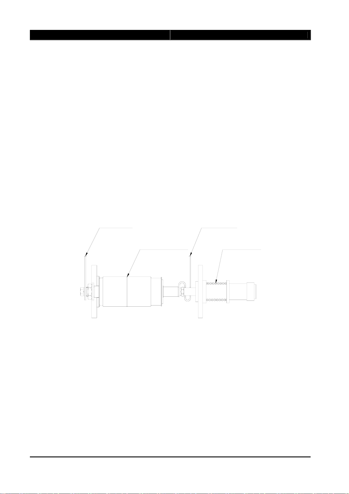
3.2. MAGNETIC ACTUATOR
The magnetic actuator designed by the newest technology delivers force to the interrupter. Since
the magnetic actuator consumes low energy, actuator switching operation can be simply achieved
through rectifying circuit with the low voltage AC 110 or 220V supplied from an external power
sources and battery charged with the low voltage sources.

EVR AUTOMATIC RECLOSER http://www.entecene.co.kr
11
ENHANCED TECHNOLOGY
The permanent magnetic actuator mechanism has just one moving part.
Thus the dramatic reduction in part gives a corresponding increase in reliability. Especially, as the
actuator uses magnetic latching and uses trip and close coil separately, the actuator consists of the
fewest components and can provides zero-maintenance operation.
The actuator driving arm is made of high strength aluminum alloy and delivers force to the
interrupter. When pulse current flows into the close coil, the plunger of magnetic actuator is moved
by the induced magnetic force to drive the interrupter to close position, and the actuator is then held
in the closed position. In contrast, when pulse current flows into the trip coil, the plunger is
released from the magnetic latch and the interrupter is moved to trip position.
Figure 3-2. The principles of magnetic actuator operation
3.3. BUSHING
Bushing is mounted on the top of the recloser tank and supplied with either porcelain or polymeric
bushing(EPR or Silicone rubber) depending upon user’s requirements.
The ring core CT is mounted on the lower part of bushing inside of the recloser tank arranged at the
fixed position of interrupter and senses the current flow.
This current information is transmitted to the micro-processor based relay via the multi-core cable.
Capacitor voltage divider (CVD) is available in case of using polymeric bushing to measure and
sense the secondary voltage for signaling use.
EVR AUTOMATIC RECLOSER http://www.entecene.co.kr
12 ENHANCED TECHNOLOGY
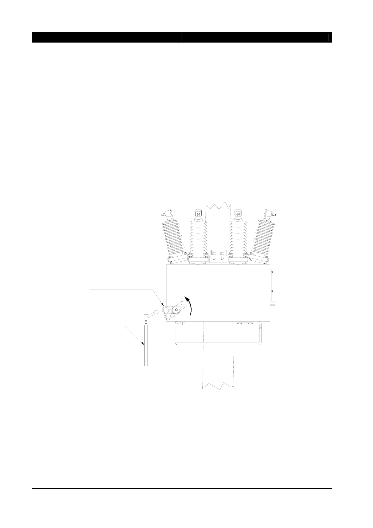
3.4. MANUAL TRIP/LOCKING DEVICE
During control circuit faults or line repair, users can locally trip or lock the Recloser with the
manual Trip/Locking device positioned on the front side of main tank. It can be manually operated
by COS hot stick. If Trip/Locking device lever is in lock position, the Recloser can't be operated by
local/remote control due to actuator power-off.
In this lock position, the user should push the manual Trip/Locking device up to the trip position to
release the locking status of the recloser and then the recloser can be operated by local or remote
control.
The recloser can be opened manually by using a hot stick to pull down the manual trip handle and
the recloser with further pulling down can be locked.
Manual trip &
Locking device
Hot stick
TRIP
LOCK
Figure 3-3. Manual Trip/Locking device of the recloser
EVR AUTOMATIC RECLOSER http://www.entecene.co.kr
13
ENHANCED TECHNOLOGY
3.5. SF6 GAS
3.5.1. General
The high purity SF6 gas filled with 0.5bar gauge keeps the insulation of the equipment and prevent
corrosion of the main tank components.
3.5.2. Specification of Sulphur Hexa Fluoride Gas (SF6)
Table 3-1. Specification
Determination Specification Unit Analysis
Purity >99.9 % wt >99.9
CF4 ≤ 0.05 % wt < 0.03
Air ≤0.05 % wt <0.03
Water ≤50 Vppm <50
Acidity as HF ≤0.3 mg/kg <0.3
Hydrolye, fluor ≤1 mg/kg <1
Table 3-2. Physical properties
Sublimation point (1.0133 bar) -63.9℃
Melting point (2.26 bar) -50.8℃
Vapour pressure (20℃) 21.08 bar
Critical temperature 45.55℃
Critical pressure 37.59 bar
Critical density 0.74 kg/l
Gas density (20℃, 1bar) 6.07 g/l
Liquid density (0℃, 12.65 bar) 1.56 kg/l
Acoustic velocity in SF6 129.06 m/sec.

EVR AUTOMATIC RECLOSER http://www.entecene.co.kr
14 ENHANCED TECHNOLOGY
3.5.3. SF6 gas pressure-Temperature Curve
A
l
a
m
p
r
e
s
s
u
r
e
(
0
.
2
k
g
/
c
m
G
)
N
o
r
m
a
l
f
i
l
l
i
n
g
p
r
e
s
s
u
r
e
(
0
.
5
k
g
/
c
m
G
a
t
2
5
C
)
S
a
f
t
y
d
e
v
i
c
e
o
p
e
r
a
t
i
n
g
p
r
e
s
s
u
r
e
Figure 3-4. SF6 gas pressure -Temperature curve
3.6. MOLECULAR SIEVE
The molecular sieve to be used is type 13X and other designations must not be used in SF6 gas.
The 13X has a controlled pore size of about 9 angstrom (0.9㎜) as typical chemical Na2O, Aℓ2O3,
2.5SiO2, nH2O.
A polyester bag containing molecular sieve beads is placed inside the enclosure and the control
cubicle.
Molecular sieve 13X is commonly used for the concurrent removal of H2O and CO2from gas, air
streams and removal of H2S.
Molecular sieve 13X can be regenerated by evacuating or purging, usually at elevated temperatures
ranging from 200℃to 300℃.
Higher temperature may cause physical degradation of the molecular sieve structure.

EVR AUTOMATIC RECLOSER http://www.entecene.co.kr
15
ENHANCED TECHNOLOGY
Typical properties shows as follows;
Table 3-3. Typical properties
Typical properties
Nominal pore diameter 9 angstrom(0.9㎜)
Type of crystal structure hexagonal
Bulk density 680g/ℓ
Water content(as shipped) 1.5% wt (max)
Heat of absorption(max) 4200kj/kg·water
Bead size(nominal) 2.5∼5㎜, 2∼3㎜, 1∼2㎜
4×8mesh, 8×12mesh, 10∼18mesh
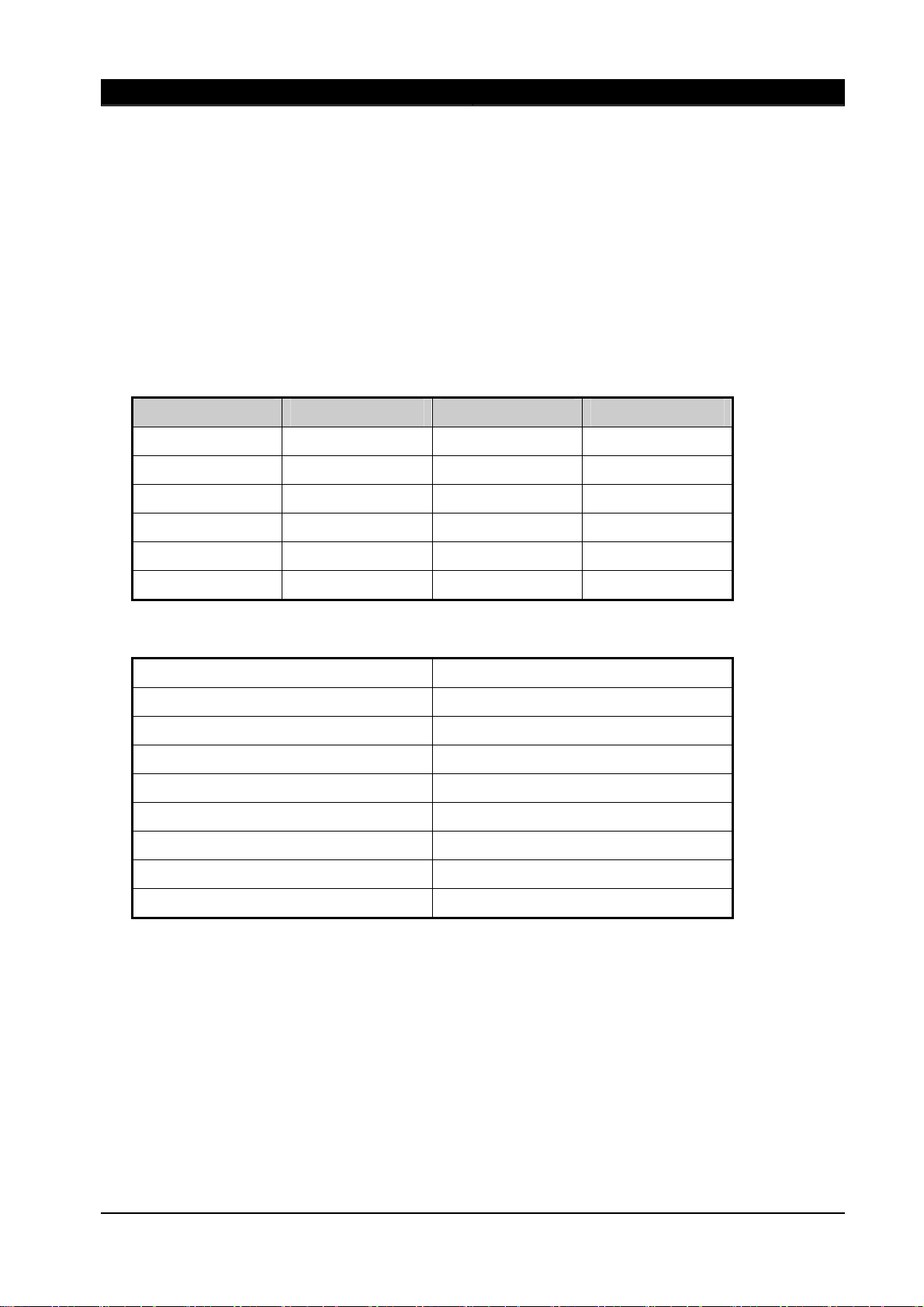
3.7. BATTERYAND BATTERY CHARGER
The battery for operating the Recloser’s components and control circuit is placed in the lower part
of the control cubicle and can be easily replaced. The battery life is usually 5 years, but it can be
shortened depending on how it is handled. The fully charged battery is enough for 30 hours
operation without an external power source.
Battery specification shows as follows;
Table 3-4. Battery Specification
Battery Specification
Battery Type ES18-12
Nominal Voltage 12V
Nominal Capacity 18 amp-hours
Battery Dimension 181 ×76 ×167mm
Self-discharge Versus Time +20℃3%/month, +40℃10%/month
Service life Time Max. 5 years at +20℃
Battery Connector(CN11) Molex Connector 3191-2R
Battery Charger
Charge Voltage 27.5Vdc(±0.5V)
Charge Current Max 300mA

EVR AUTOMATIC RECLOSER http://www.entecene.co.kr
16 ENHANCED TECHNOLOGY
3.8. CONTROL CUBICLE
The Recloser control cubicle is designed for outdoor pole mounted and substation operation which
is made of anti-corrosion stainless steel.
The door is locked with three position locking devise and sealed with replaceable urethane foaming
packing.
All vents are screened against vermin entry and the cubicle inside is fully covered with adiabatic
faming material which protects the inside components from the rapid temperature variation.
The control cubicle outside is protected with a sunshine shield cover which is required for keeping
the life cycle from shortening because the temperature sensitive electronic components and battery
is affected by sunshine heating.
The microprocessor based control compartment is completely sealed against water entry even
though the hatch door is opened in the rain during the recloser operation.
The condensation of the cubicle inside can be expected to foam due to the temperature variation
under the atmospheric conditions such as tropical and moderate climate, however, any
condensation does not affect any electronic components arranged with fully insulated sealed and
well vented design.
Figure 3-5. Control cubicle layout
Consequently, any condensation on metal surface will run out of the bottom and automatically
dried without affecting the electronic modules by ventilation and self heating.
The standard control cubicle contains the relay, batteries for control power and mechanism driving
power.

EVR AUTOMATIC RECLOSER http://www.entecene.co.kr
17
ENHANCED TECHNOLOGY
The control cubicle must not installed outdoors without the sunshine shield cover in the places of
solar heating.
Detailed control and relay, Please refer to our separate EVRC2A manual.
The control cubicle is shown in Figure 3-5 on previous page.
3.9. AUXILIARY POWER SUPPLY
Auxiliary power source is derived from either of the following;
yFrom an external power source of 110V and 220V supplied by auxiliary power transformer.
yFrom low voltage supply connected to the utility distribution line.
yIn addition to above, it is preferred to use from an external DC 110V supply for substation
application as option.
Actually, auxiliary supply is used to operate the auto recloser through rectifying circuit and
maintain charge on the sealed lead-acid batteries.
The operation of recloser is fulfilled with the auxiliary power supply through the rectifying circuit
regardless of charging of the sealed lead-acid batteries. The battery is used for the back-up
operation of the recloser when auxiliary power supply is lost.
The battery for operating the recloser is placed in the lower part of the control cubicle and arranged
to be easily replaced.
The battery life is predicted to use for 5 years service as recommended by the battery
manufacturer’s data, but it can be shortened for its life on how it is handled and fitted with the
environments.
The battery is enough to operating the recloser for 30hours and over 500 events without external
power supply. When the batteries are nearly exhausted in showing below DC 15V when battery is
tested with load, please replace the batteries with new one as indicated in section 3.7 battery
specification or consult with manufacturer.
CAUTION: Auxiliary Power Transformer shall be installed in the source side of user system.
External Power of EVRC2A Control shall be supplied from Source side in order to perform a
normal sequence in case that a fault line occurs. When the recloser trips, the external power of
EVRC2A Control shall not be lost.

EVR AUTOMATIC RECLOSER http://www.entecene.co.kr
18 ENHANCED TECHNOLOGY
OF RECLOSER
CONTROL CABLE
EARTH TERMINAL
MOUNTING BRACKET
EARTH CABLE
Epoxy Mold Transformer
110V OR 220V 500VA
THE DIGITAL CONTROL CUBICLE
Figure 3-6. Auxiliary power supply

EVR AUTOMATIC RECLOSER http://www.entecene.co.kr
19
ENHANCED TECHNOLOGY
CONTROL CABLE
LOW VOLTAGE SOURCE SUPPLIED
BY UTILITYE
110V OR 220V 5KVA Tr. or
EARTH CABLE
MOUNTING BRACKET
EARTH TERMINAL
AUX. TRANSFORMER
THE DIGITAL CONTROL CUBICLE
OF RECLOSER
Figure 3-7. Auxiliary power supply

EVR AUTOMATIC RECLOSER http://www.entecene.co.kr
20 ENHANCED TECHNOLOGY
3.10. GAS FILLING VALVE
This valve is on the side of the recloser tank and “CARE” must be paid, not to be opened with
protection cap for preventing the gas leakage on the filling value.
SF6 gas filling valve detail is shown in Figure 3-8.
Figure 3-8. Gas Filling Valve
3.11. ACCESSORIES
1) ON/OFF indication is located on the bottom inside of the main tank to be seen transparently
from the underneath of the tank.
2) Operating counter is provided in the control cubicle and if fitted, available at the bottom of the
main tank.
3) SF6 gas pressure sensor is available, if required as option.
4) Pressure rupture device is mounted on the side of recloser tank for protection of overpressure
due to overheating of internal arc.
This manual suits for next models
1
Table of contents
Other Entec Circuit Breaker manuals

Popular Circuit Breaker manuals by other brands

ABB
ABB S800U quick start guide

Bticino
Bticino MA 400/630MT instruction sheet

Siemens
Siemens 3VT9000-1UX00 operating instructions

Eaton
Eaton Crouse-Hinds GFSX1 Installation & maintenance information

Cutler-Hammer
Cutler-Hammer VCP-TR Series Instructions for the Use, Operation and Maintenance

Block
Block PM-0748-200-0 manual


