Entes GEM-15 RTU User manual

GEM-15 RTU
1
Safety Conditions
WARNING: To operate the device without any malfunctions and to keep the warranty
right, this user manual must be complied. Therefore, this user manual must be read carefully
before the commissioning of the device! Since this user manual contains important information
about the device settings and functions, it must be kept in a place near the device.
Warnings
The device doesn’t contain any auxiliary power supply. Our company cannot be held
responsible for faults arising from power outages.
The device must be energized after all its connections are checked.
The fuse that is used must be Super-Quick-Acting FF type and its current limit value
must be 1 A.
Device is only for rail mounting.
The cover of the device must not be removed after it has been energized.
The device must be kept away from environments with high humidity, vibrations or
dust.
The device must be operated between -20 ° C and 50 ° C temperatures.
Damaged devices should under no circumstances be installed and commissioned.
The device should not be cleaned with cleaning products containing solvents () or
abrasive materials.
The device should be cleaned only with a dry cloth.
The device should only be serviced by the authorized seller.
Installation and electrical connections must be done by the technicians at the site by
following the instructions in the user manual.

GEM-15 RTU
2
The manufacturer can’t be held responsible for the consequences resulting from failure
to comply with these warnings. If these warnings are ignored, the device will not
qualify for warranty.
Index
1Introduction .....................................................................................Hata! Yer işareti tanımlanmamış.
1.1 Usage Areas .............................................................................Hata! Yer işareti tanımlanmamış.
1.2 General Features.....................................................................Hata! Yer işareti tanımlanmamış.
1.3 Technical Features..................................................................Hata! Yer işareti tanımlanmamış.
1.3.1 Modbus Gateway Feature:..................................................................................................................... 7
1.3.2 Automatic MODBUS-RTU Querying................................................................................................... 7
1.3.3 Alarm Control: ...................................................................................................................................... 9
1.3.4 Data Recording:..................................................................................................................................... 9
1.3.5 Input/Output Terminals.................................................................. Hata! Yer işareti tanımlanmamış.
1.4 Applied Standards...........................................................................................................................10
1.5 Front, Side, Back Panels.................................................................................................................11
1.6 Hardware Structure and Features ........................................Hata! Yer işareti tanımlanmamış.
2Device Usage....................................................................................Hata! Yer işareti tanımlanmamış.
2.1 Content of Box.........................................................................Hata! Yer işareti tanımlanmamış.
2.2 Necessary Equipment and Accessories ..................................................................................15
2.3 Mounting..................................................................................Hata! Yer işareti tanımlanmamış.
2.4 Electrical Connections............................................................Hata! Yer işareti tanımlanmamış.
2.5 Inputs and Outputs..................................................................................................................19
2.6 Device Management with PC-based Server Software ..........................................................20
2.6.1 GEM15 Server Software ..................................................................................................................... 20
2.6.2 Main Menu Items and Their Functions ............................................................................................... 20
2.6.3 Modem Settings ............................................................................. Hata! Yer işareti tanımlanmamış.
2.6.4 Starting Settings and Defining the Modem to the Server............... Hata! Yer işareti tanımlanmamış.
2.6.5 Adding The Modem To Be Monitored........................................... Hata! Yer işareti tanımlanmamış.
2.6.6 Modbus Parameter Settings................................................................................................................. 25
2.6.7 Defining Device (Defining RTU)........................................................................................................ 26
2.6.8 Defining Parameter ........................................................................ Hata! Yer işareti tanımlanmamış.
2.6.9 AI/DI/DO/RELAY Settings................................................................................................................ 42
2.6.10 Activating Digital Outputs......................................................... Hata! Yer işareti tanımlanmamış.
2.6.11 Defining Alarm.......................................................................... Hata! Yer işareti tanımlanmamış.
2.6.12 Creating Alarm for Digital Inputs.............................................. Hata! Yer işareti tanımlanmamış.
2.6.13 Creating Alarm for Analog Inputs............................................. Hata! Yer işareti tanımlanmamış.
2.6.14 Creating Modbus Alarm............................................................ Hata! Yer işareti tanımlanmamış.
2.6.15 Settings...................................................................................... Hata! Yer işareti tanımlanmamış.
2.6.16 Date-Time Settings.................................................................... Hata! Yer işareti tanımlanmamış.
2.6.17 Data Record Fields .................................................................... Hata! Yer işareti tanımlanmamış.
2.6.18 Connection Settings................................................................... Hata! Yer işareti tanımlanmamış.
2.6.19 Ethernet, GPRS and Serial Port Settings........................................................................................ 85
2.6.20 Instantaneous Value Monitoring................................................Hata! Yer işareti tanımlanmamış.
2.6.21 DO/RELAY Control Field......................................................... Hata! Yer işareti tanımlanmamış.

GEM-15 RTU
3
2.6.22 Periodic Parameter Monitoring Window................................... Hata! Yer işareti tanımlanmamış.
2.6.23 Alarm Monitoring Window.......................................................Hata! Yer işareti tanımlanmamış.
2.6.24 Reports....................................................................................... Hata! Yer işareti tanımlanmamış.
2.6.25 Downloading Logs From The Device ....................................... Hata! Yer işareti tanımlanmamış.
2.6.26 Listing........................................................................................ Hata! Yer işareti tanımlanmamış.
2.6.27 Language Selection ................................................................... Hata! Yer işareti tanımlanmamış.
2.6.28 GEM-15 Register Table................................................................................................................ 100
2.6.29 Installing and Updating The Firmware......................................................................................... 102
2.6.30 Necessary Information............................................................... Hata! Yer işareti tanımlanmamış.
3Configuration...................................................................................Hata! Yer işareti tanımlanmamış.
3.1 Introduction.............................................................................Hata! Yer işareti tanımlanmamış.
3.2 AT COMMAND SET AND SOFTWARE.........................................................................114
3.2.1 AT+ LOCALIP ................................................................................................................................. 114
3.2.2 AT+ MAC......................................................................................................................................... 114
3.2.3 AT+ GATEWAY.............................................................................................................................. 114
3.2.4 AT+ NETMASK............................................................................................................................... 115
3.2.5 AT+ SERVERIP ............................................................................................................................... 115
3.2.6 AT+ SERVERPORT......................................................................................................................... 115
3.2.7 AT+ LISTENPORT .......................................................................................................................... 116
3.2.8 AT+ GPRSAPN ................................................................................................................................ 116
3.2.9 AT+ GPRSNAME ............................................................................................................................ 116
3.2.10 AT+GPRSPSSW.......................................................................................................................... 117
3.2.11 AT+ GPRSIP................................................................................................................................ 117
3.2.12 AT+ COMTYPE .......................................................................................................................... 117
3.2.13 AT+ RTUSETTING..................................................................................................................... 117
3.2.14 AT+ PROTOCOL ........................................................................................................................ 118
3.2.15 AT+ VERSION ............................................................................................................................ 118
3.2.16 AT+ SERIALNO.......................................................................................................................... 118
3.2.17 AT+ CONNECTION.................................................................................................................... 118
3.2.18 AT+ CSQ...................................................................................................................................... 119
3.2.19 AT+ DEFAULT ........................................................................................................................... 119
3.2.20 AT+ SETTIME............................................................................................................................. 120
3.2.21 AT+ FORMATFS ........................................................................................................................ 120
3.2.22 AT+ RESET ................................................................................................................................. 120
3.2.23 Installing USB Drivers For AT Command Software.................................................................... 120
3.2.24 Learning The Defined COM Port Of Your Modem ..................................................................... 123
3.2.25 Configuration with AT Command Console via Hyper Terminal ................................................. 124
3.2.26 MikroTerminal Software Installation via Local USB................................................................... 131
3.2.27 Using MikroTerminal Software.................................................................................................... 135
4Troubleshooting...............................................................................................................................139
5Help..................................................................................................Hata! Yer işareti tanımlanmamış.

GEM-15 RTU
4
1Introduction
GEM-15 modemRTU is a professional device that collects a combination of features, such as
alarm management, automatic RTU query, data logging, MODBUS protocol conversion, TCP/IP
communication via GSM and Ethernet network and smart relay.
1.1 Usage Areas
Since GEM-15 supports GSM infrastructure; it can be used for monitoring, alarm and control
purposes at hard-to-reach places such as where there’s no Ethernet connection, water discharge
station and wells, oil pipelines, cell towers. The device can be a solution at many areas where mobile
monitoring and control is needed such as bank branches, ATMs, server rooms, cold rooms in health
and food sectors, industrial processes, agricultural irrigation, monitoring of electrical and natural gas
energy, transportation sector, terrestrial broadcasting stations, cell towers, chain stores.
1.2 General Features
Some of the superior features that the device has are listed below.
1. Creating MODBUS gateway
2. Automatic MODBUS-RTU querying
3. Alarm management
4. Smart Relay
5. Data logging
6. Input/Output terminals
7. SMS sending
8. TCP/IP communication via GPRS
9. TCP/IP communication via Ethernet

GEM-15 RTU
5
1.3 Technical Features
General
Supply
9-36 VDC, protected
Power
< 5 W
CPU Clock Speed
80 MHz
RTC (Real Time Clock)
Available
Input Filters
Median and mean filters are applied at
analog inputs.
Analog low pass filter is available at
digital inputs. Software-based debounce
control filter is also available.
Digital I/O Frequency
Digital Outputs:
OFF to ON Response 32 µs
ON to OFF Response 150 µs
Digital Inputs:
OFF to ON Response < 2 ms
ON to OFF Response < 12 ms
ADC Sampling Period
640 SPS (sample per second) per channel. 4
SPS after filtering operations
Program Uploading
Possibility of updating firmware and software
via USB
Communication
Interfaces
GSM
GPRS, MODBUS TCP support
Serial Port (RS485)
15 kV ESD protection, galvanic isolation,
MODBUS RTU
Environment
Conditions
Operating Temperature
-20°..50° C
Storing Temperature
-40°..85° C
Humidity
5..95Rh
Operating Altitude
< 2000m
Integrated
Inputs/
Outputs
Digital Inputs
Module Input
4 (Sink)
Voltage Range
0-50VDC
ON Voltage level
5 VDC - 50 VDC
OFF Voltage level
0- 3 VDC

GEM-15 RTU
6
Input Current
Type 0.70 mA 24 VDC
Max. Input Current
1.50 mA 50 VDC
Input Impedance
>3.3 MΩ
Input GND common
lead
1(4 points/common) Isolated
Max. drawn current
(24VDC)
Max. 5.6 mA(All Inputs On)
Max. drawn current
(50VDC)
Max. 12.04 mA(All Inputs On)
OFF to ON Response
< 2 ms
ON to OFF Response
< 12 ms
Insulation
1KV
Digital Outputs
Module Output
Output with 4(Sink) Transistors
Voltage Range
3.3 - 50 VDC
Max. Output Current
125 mA/point , 500 mA/common
Min. Output Current
0.42 mA/point , 1.68 mA/ common(3.3 V)
Max. Leakage Current
0.01 mA
Voltage Drop
2.3 VDC @ 0.76 mA
OFF to ON Response
32 µs
ON to OFF Response
150 µs
Input GND common
lead
1 (4 points/common) Isolated
Auxiliary Voltage
Input
5- 50 VDC Max 48 mA(All Outputs On)
Max. Drawn Current
Max. 0.5 A (All Outputs On)
Analog Inputs
Module Current Input
2
Module Voltage Input
2
Current Input
Accuracy
1% accuracy, 12Bit resolution
Voltage Input
Accuracy
1% accuracy, 12Bit resolution
Current Input
0(4)-20mA
Input Resistance (A)
120 OHM
Voltage Input
0(2)-10V

GEM-15 RTU
7
Input Resistance (V)
40 KOHM
Input GND common
lead
1(4 points/common)
Relay
Outputs
Module Output
4 relays
Relay Contact Outputs
Com-NO (Normally Open)
Max. Contact Current
3A@250VAC 3A@30VDC
Log
Log recording time
resolution
1s
Log record capacity
Recording 19600 separate parameter with
time-stamp and parameter information
Alarm log recording:
Storing parameter with time-stamp at the start
and end instances
Table 1 Technical Features
1.3.1 Modbus Gateway Feature:
The device will basically have two communication interfaces. One of these interfaces is local
network. On local network, RS485 is used as the physical layer and MODBUS-RTU protocol is
supported. Slave devices that are going to be controlled or whose data are going to be read are
connected to this network. For the other communication interface, GPRS and/or Ethernet
technologies are used as the physical layer and MODBUS-RTU protocol is supported.
Communication with servers and SCADA systems is established via this second interface.
When the device works in MODBUS GATEWAY mode, it adds the packet that it took from
MODBUS-TCP interface to a queue, then converts the MODBUS-TCP request packet to MODBUS-
RTU request packet by taking it from the queue one by one and sends it to local network on RS485.
The slave device on the local network creates the MODBUS-RTU response packet for this request
packet and sends it. Then, the MODBUS GATEWAY device sends this response that it received
from RS485 interface to the related point by converting it to MODBUS-TCP packet.
1.3.2 Automatic MODBUS-RTU Querying
One of the most important features of the device is automatic querying. 247 pieces of RTUs can
be connected to each device (modem) with RS-485. In addition to creating bridge between
MODBUS RTU and MODBUS TCP, it queries the defined MODBUS registers in defined time
intervals and can automatically manage functions such as sending information to server according to
incoming responses, recording time-stamps and alarm management.

GEM-15 RTU
8
MODBUS RTUs to be queried and information about the registers of these RTUs are created in
a file called querying table and loaded to the device. Queries defined in this file are carried out
automatically by the device.
The time interval to make automatic queries can be defined by the user in minutes. Thanks to
the automatic querying mechanism to be developed:
Communication load between server and MODBUS GATEWAY device decreases
significantly.
Real-time alarm management can be done.
A distributed alarm architecture is created by transferring the workload from the server to
the device. By this means, a more reliable tracking/management solution is provided.
Figure 1 Automatic Querying
In the traditional method, many messages must be transmitted on the system when alarm management
is done from the server.
Message transmitting happens as below:
Server sends the MODBUS-TCP request message to MODBUS GATEWAY.
MODBUS GATEWAY analyzes the arriving MODBUS-TCP request message and
sends the MODBUS RTU request message to RTU.
RTU responds to the MODBUS RTU request message.
This response is converted to MODBUS-TCP response by the MODBUS GATEWAY
and sent to the server.

GEM-15 RTU
9
Server analyzes the received response. If alarm control is going to be done, it is done at
this level. Necessary control message is sent again.
Not only the management and alarm control processes are done more quickly and securely with
the device, but less message transmission occurs in the system. This means immediate alarm
management and a more economical solution.
Management process for the developed device occurs as below:
MODBUS GATEWAY device sends the query message to the RTU automatically.
RTU sends the response message.
MODBUS GATEWAY inspects this response and carries out the necessary processes
immediately when an alarm happens. These processes can be triggering the digital outputs of
the device, closing the output relays or sending SMS.
If an alarm is detected, the server is informed by sending an additional information message.
1.3.3 Alarm Control:
The device queries the registers of MODBUS RTUs that have been defined by the user in an
adjustable interval and does alarm control by comparing the register value with the defined limit
values as inside range, outside range, smaller than and greater than.
Additionally, alarms can be defined for the device’s digital input/output units and analog
inputs. Device’s inputs and MODBUS alarm conditions can be processed with an AND function and
assigned to the outputs of the device. After the analog input values are corrected with a set of
coefficients (as y = mx + c where m and c are parametric coefficients), they are processed as entries
for the alarm control process as inside range, outside range, smaller than and greater than.
If an alarm occurs after the comparison processes, triggering options such as digital outputs,
relay outputs, sending SMS or sending TCP message can be carried out.
1.3.4 Data recording:
The device can record the defined registers of the RTUs that are connected to it, the states of
analog inputs and digital/analog outputs to its internal memory in a user-specified interval by adding
time-stamp information.
1.3.5 Input/output Terminals
The device has optically-isolated internal digital inputs/outputs. All digital inputs/outputs and
analog inputs of the device are accessible as internal MODBUS registers.

GEM-15 RTU
10
GEM-15 modemRTU works in master mode on Modbus RTU network. MODBUS RTU
parameters (can be different parameters of different devices) that have been defined by the user can be
queried in an adjustable interval and separate functions can be assigned for each queried parameter. By
this means, real-time querying and alarm management is achieved.
1.4 Applied Standards
Vibration Test IEC (60068-2-6) is the standard process to determine the resistance of device
and other equipment against determined sinusoidal vibration strength levels
Mechanical Shock Test EN (60068-2-27) is the standard process to determine the resistance
against recurring and nonrecurring mechanical shocks at determined strength levels
Climate Test EN (60068-2-2) is the dry heat experiment that can be applied to both heat-
dissipating and non-heat-dissipating experiment samples
Safety Test EN (60950-1) is applicable to mains-powered or battery-powered information
technology equipment, including electrical business equipment and associated equipment,
with a rated voltage not exceeding 600 V
ESD EN (61000-4-2) relates to the immunity requirements and test methods for electrical and
electronic equipment subjected to static electricity discharges, from operators directly, and
from personnel to adjacent objects.
EFT EN (61000-4-4) relates to the immunity requirements and test methods of electrical and
electronic equipment to repetitive electrical fast transients.
Surge (61000-4-5) relates to the immunity requirements, test methods, and range of
recommended test levels for equipment to unidirectional surges caused by overvoltages from
switching and lightning transients.

GEM-15 RTU
11
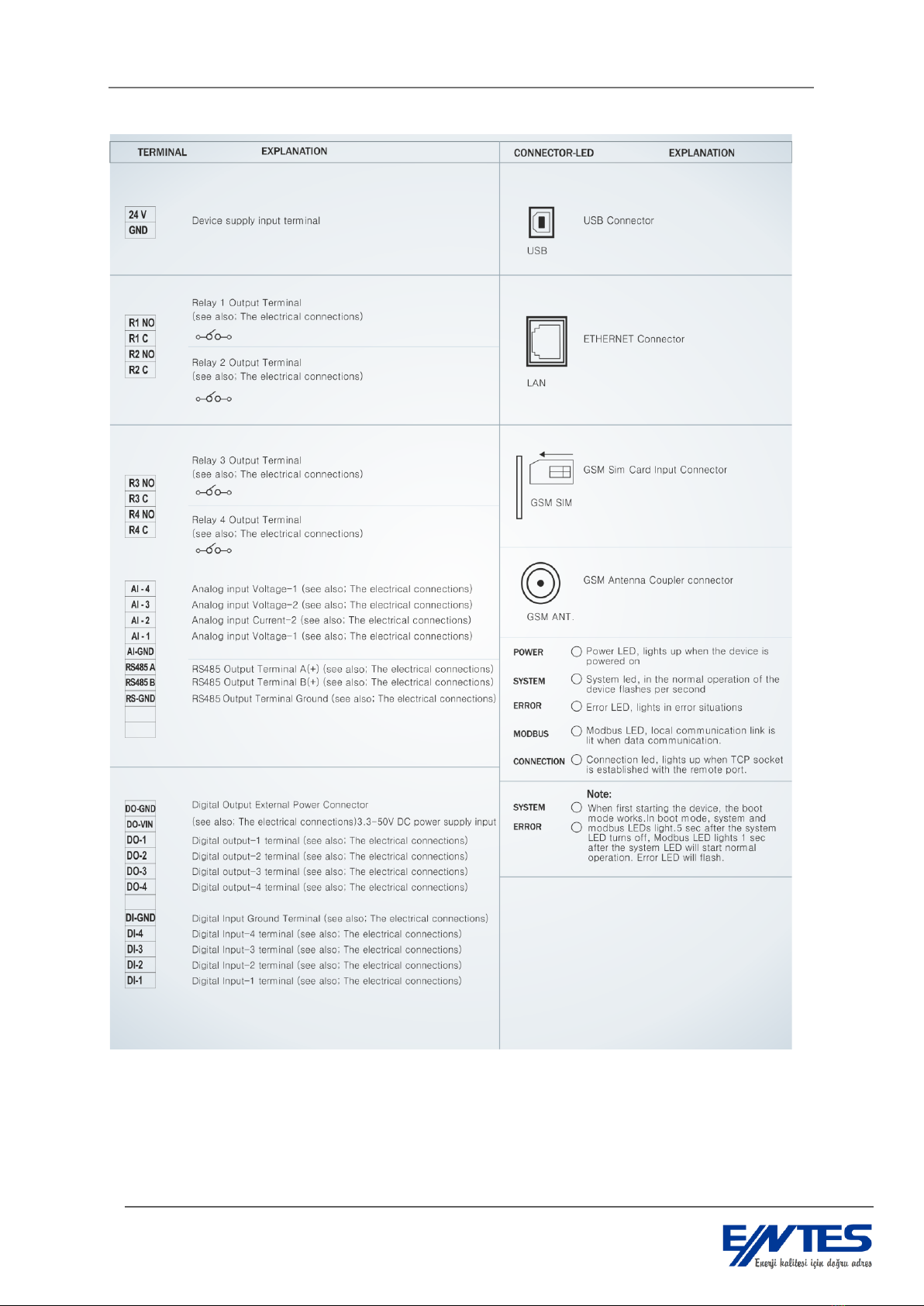
1.5 Front, Side, Back Panels
Terminals on the GEM-15 are located as below.
Figure 2 Front View
GEM-15 RTU
12
Figure 3 Terminal Explanations

GEM-15 RTU
13
1.6 Hardware Structure and Features
Supply 9-36V (24 VDC is commonly used.), protected
Power <5W
CPU clock speed 80Mhz
Real-time clock
Remote Monitoring, Control and Communication Units:
10/100 BaseT Ethernet port
GSM/GPRS
Local Network Communication Units:
1 RS485 port with galvanic isolation

GEM-15 RTU
14
1 USB device port (For making service-purpose device settings)
Input/Output Units:
4 optically-isolated digital inputs
4 optically-isolated digital outputs
4 dry contact relay outputs (5 A, 250 VAC)
2 analog current inputs (4-20 mA)
2 analog voltage inputs (0-10 V DC)
Recording and Parameter Memory:
32 MBit Flash
Serial Interface:
Interface: Software-selectable RS485
Communication Speed: Software-selectable between 300 and 115200
Serial Communication Parameters:
Data Bits: 7 or 8 bit
Parity: odd, even, none
Stop Bits: 1
Modbus Protocol Support
Modbus RTU
Modbus TCP
Operating Modes
Automatic Querying
Modbus Gateway
Indıcators (LED)
Power: Turns on when device is energized.
Error: Turns on in case of an error
System: Blinks in a 1 second interval
Modbus : Indicates that data transmission with serial device is occurring
Remote Connection: Indicates that connection with remote PC has been established
Isolation:
Serial Port: 15 kV ESD protection RS485, galvanic isolation
Power Input: Nonrecurring 600 W 10/100 µs surge protection
Environmental Conditions:
Operation: -20° to 50° C
Storage: -40° to 85° C

GEM-15 RTU
15
Mechanical:
Rail-mount, DIN7 enclosure
Management:
With configuration software via local USB
With configuration software via Ethernet/GPRS
Access to all local parameters during Modbus Slave Mode
Software:
Configuration Software
Monitoring, management and recording software for single device
Other Functional Features:
Gateway Operating Mode
Ability to automatically find RTUs that are connected to its RS-485 port
SMS querying
Ability to monitor and control via any of the GPRS or Ethernet connection points
Adjusting log recording interval between 1 minute and 2 hours
FIFO memory architecture where the new entry is recorded after the first entry is deleted when
the memory becomes full
2Device Usage
2.1 Content of Box
5 terminal blocks
GSM network antenna
USB configuration cable with ferrite
Serial loader update software –CD content.
GEM15 user manual –CD content.
Mikroterminal configuration software –CD content.
2.2 Necessary Equipment and Accessories
The equipment that are listed above arrives with the device. Additionally, following items are
optional:
PS -242 24 V 1 A 24 W power supply
Antenna with magnetized base and 3 m extension cable for basements, panels that create
faraday cages
Note: These can be purchased separately or together by ordering as GEM-15 PS and
GEM –15 PS A models. Please refer to the price list for price advantages.

GEM-15 RTU
16
2.3 Mounting
Excessive force during installation may damage the device.
The screws for cables that are in the terminal blocks must be tightened safely.
2.4 Electrical Connections
Figure 4 Digital Outputs Connection Diagram

GEM-15 RTU
17
Figure 5 Digital Inputs Connection Diagram
Figure 6 Relay Connection Diagram

GEM-15 RTU
18
Figure 7 Analog Input Connection Diagram
Figure 8 Supply Voltage Connection
Figure 9 RS485 Communication Connection Diagram

GEM-15 RTU
19
Current and voltage input terminals are designed for 2,5 mm2diameter cables but cables up to 4 mm2
are supported.
Maximum recommended cable diameter for the digital input/output terminals is 1.5 mm2.
CAT-5 cable is recommended for RS-485 input terminals.
2.5 Inputs and Outputs
Figure 10 Digital Input Circuit
Figure 11 Digital Output Circuit
Figure 12 Relay Circuit

GEM-15 RTU
20
2.6 Device Management with PC-based Server Software
Windows-based server software, which is provided with the device, is used to change, manage
and monitor device settings such as automatic querying, alarm control, logging. A single device can be
managed with this server software. This software is the interface where operations such as defining of
RTUs connected via RS-485, changing automatic querying settings, monitoring alarm states are done.
2.6.1 GEM15 Server Software
2.6.2 Main Menu Items and Their Functions
Menus except Modem Settings are passive on server software main menu.
The title bar of the server software shows the software version and if a modem has been
selected.
Figure 13 Main Menu Items and Their Functions
The status bar of the server software window contains GSM signal level, IP information of the
connected modem, MAC address of the connected modem, memory status and existence of
connection.
When the modem is selected from the “Modem Settings” menu, other menus become active.
After the modem has been selected, the title biar of the software window shows the modem name
instead of the version number.
Table of contents
Other Entes Gateway manuals

Popular Gateway manuals by other brands

Magnum Energy
Magnum Energy MagWeb GT owner's manual

ABLELink
ABLELink ABLELink MB5000 Series user manual

Devices World
Devices World 3000 Series user manual

Verizon
Verizon FiOS Quantum Setup guide

Alcatel-Lucent
Alcatel-Lucent OmniAccess 5510 ADSL Cli configuration guide

RBH Access Technologies
RBH Access Technologies LIF-200 Quick setup guide


