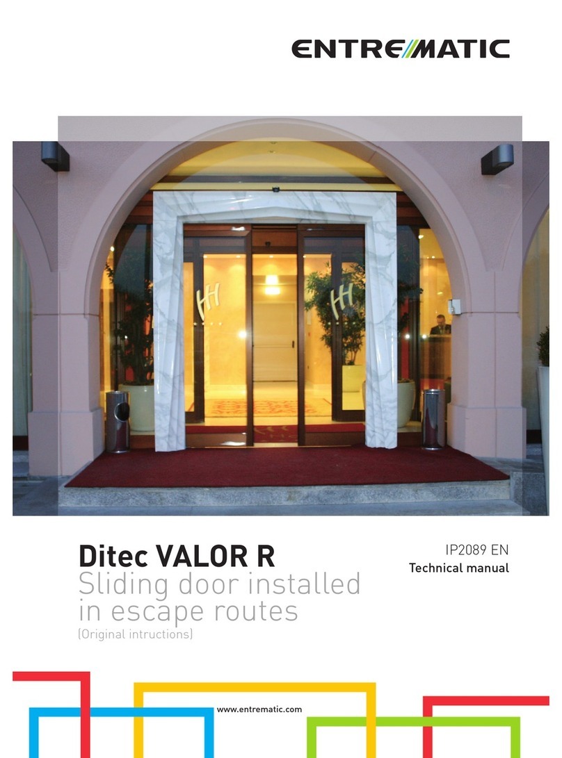
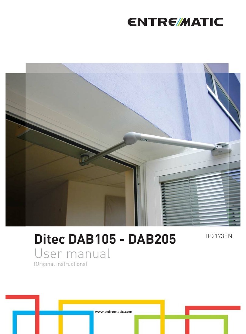
Entrematic Ditec DAB105 User manual

Ditec DAB105
Swing doors
(translation of the original instructions)
www.entrematic.com
IP2159EN
Technical Manual

2
IP2159EN - 2017-06-12
Contents
Key
Subject Page
1. General safety precautions 3
2. General safety precautions for the user 4
Declaration of incorporation of partly completed machinery 5
6
3. Technical specifications 7
4. Standard installation 8
5. Dimensions 9
6. Main components 10
7. Installation 11
7.1 Preliminary checks 11
7.2 General information 11
7.3 Installation examples 12
7.4 Removing the cover 12
8. Automation with articulated arm DAB805PSA 13
8.1 Automation preparation and fastening 13
8.2 Fixing the arm 16
8.3 Assembling the left-hand articulated arm 16
9. Automation with articulated arm DAB805PSAF 17
9.1 Automation preparation and fastening 17
9.2 Fixing the arm 20
10. Automation with sliding arm DAB805PLA 21
10.1 Automation preparation and fastening 21
10.2 Fixing the sliding arm 25
10.3 Fixing the door stop 26
11. Connecting to the electricity supply 27
12. Starting up the door 28
13. DAB105CU Electrical connections 29
13.1 Commands 29
13.2 Outputs and accessories 30
13.3 Adjustments 31
14. Pre-configured parameters 33
15. Door requisites for Low Energy use 34
16. Example of an application with a standard automation 35
17. ESE extension unit DAB905ESE (optional) 36
17.1 Commands 36
17.2 Outputs and accessories 38
17.3 Adjustments 38
17.4 Advanced settings available on the control panel version indicated, or subsequent versions 39
18. DAB905ESA extension unit 40
18.1 Commands 40
18.2 Outputs and accessories 41
18.3 Adjustments 42
19. Example of an application with optional extension units 43
20. Parallel and interlocked automations 43
21. Electrical start-up 47
22. Routine maintenance plan 47
23. Troubleshooting 48
24. Signs 49
i
This symbol indicates instructions or notes regarding safety, to which special attention must be paid.
This symbol indicates useful information for the correct functioning of the product.
This symbol advises you to contact the Technical Service.

3
IP2159EN - 2017-06-12
1. General safety precautions
This installation manual is intended for qualified personnel only.
Installation, electrical connections and adjustments must be performed in accordance with
Good Working Methods and in compliance with the present standards. Read the instructions
carefully before installing the product.
Incorrect installation could be dangerous.
The packaging materials (plastic, polystyrene, etc.) should not be discarded in the envi-
ronment or left within reach of children, as they are a potential source of danger. Before
installing the product, make sure it is in perfect condition.
Do not install the product in explosive areas and atmospheres: the presence of inflammable gas
or fumes represents a serious safety hazard.
Before installing the motorisation device, make all the necessary structural modifications to
create safety clearance and to guard or isolate all the crushing, shearing, trapping and general
hazardous areas.
Make sure the existing structure is up to standard in terms of strength and stability. The mo-
torisation device manufacturer is not responsible for failure to observe Good Working Methods
when building the frames to be motorised, or for any deformations during use.
The safety devices (photocells, safety edges, emergency stops, etc.) must be installed taking
into account the applicable laws and directives, Good Working Methods, installation premises,
system operating logic and the forces developed by the motorised door.
The safety devices must protect the crushing, shearing, trapping and general hazardous
areas of the motorised door. Display the signs required by law to identify hazardous areas.
Each installation must bear a visible indication of the data identifying the motorised door.
When requested, connect the motorised door to an effective earthing system that complies with
current safety standards. During installation, maintenance and repair operations, cut off the
power supply before opening the cover to access the electrical parts.
The automation protection casing must be removed by qualified personnel only.
The electronic parts must be handled using earthed antistatic conductive arms. The manu-
facturer of the motorisation declines all responsibility if component parts not compatible
with safe and correct operation are fitted.
Only use original spare parts when repairing or replacing products.
The installer must supply all information on the automatic, manual and emergency operation of
the motorised door, and must provide the user with the operating instructions.
All the rights concerning this material are the exclusive property of Entrematic Group AB.
Although the contents of this publication have been drawn up with the greatest care, Entrematic Group AB cannot be held responsible in any way for any dam-
age caused by mistakes or omissions in this publication. We reserve the right to make changes without prior notice. Copying, scanning or changing in any way is
expressly forbidden unless authorised in writing by Entrematic Group AB.
4
IP2159EN - 2017-06-12
These precautions are an integral and essential part of the product and must be supplied
to the user.
Read them carefully since they contain important information on safe installation, use and
maintenance.
These instructions must be kept and forwarded to all possible future users of the system.
This product must only be used for the specific purpose for which it was designed.
Any other use is to be considered improper and therefore dangerous. The manufacturer cannot
be held responsible for any damage caused by improper, incorrect or unreasonable use.
Avoid operating in the proximity of the hinges or moving mechanical parts. Do not enter within
the operating range of the motorised door or gate while it is moving.
Do not obstruct the motion of the motorised door or gate, as this may cause a dangerous situation.
The motorised door or gate may be used by children over the age of 8 and by people with reduced
physical, sensorial or mental abilities, or lack of experience or knowledge, as long as they are
properly supervised or have been instructed in the safe use of the device and the relative hazards.
Children must be supervised to make sure they do not play with the device, nor play/remain in
the sphere of action of the motorised door or gate.
Keep remote controls and/or any other command devices out of the reach of children, to avoid
any accidental activation of the motorised door or gate.
In the event of a product fault or malfunction, turn off the power supply switch. Do not attempt
to repair or intervene directly, and contact only qualified personnel.
Failure to comply with the above may cause a dangerous situation.
Any repairs or technical interventions must be carried out by qualified personnel.
Cleaning and maintenance work must not be carried out by children unless they are supervised.
To ensure that the system works efficiently and correctly, the manufacturer’s indications must
be complied with and only qualified personnel must perform routine maintenance on the mo-
torised door or gate. In particular, regular checks are recommended in order to verify that the
safety devices are operating correctly.
All installation, maintenance and repair work must be documented and made available to the user.
Only lock and release the door wings when the motor is switched off. Do not enter within the
operating range of the wing.
To dispose of electrical and electronic equipment correctly, users must take the product
to special “recycling centres” provided by the municipal authorities.
2. General safety precautions for the user

5
IP2159EN - 2017-06-12
Declaration of incorporation of partly completed machinery
We:
Entrematic Group AB
Lodjursgatan 10
SE-261 44 Landskrona
Sweden
declare under our responsibility that the following types of equipment:
Ditec DAB105
comply with the following directives:
2014/30/EU Electromagnetic Compatibility Directive (EMCD)
2006/42/EC Machinery Directive (MD) for the following essential health and safety requirements: 1.1.2, 1.1.3, 1.2.1,
1.2.3, 1.2.4, 1.2.6, 1.3.2, 1.3.4, 1.5.1, 1.5.2, 1.5.3, 1.5.8, 1.5.9, 1.5.10, 1.5.11, 1.6.3, 1.7.3, 1.7.4
Technical documentation for safe integration supplied.
Harmonised European standards which have been applied:
EN 60335 -1:2012 EN 61000 -6-2:2005 EN 61000 -6-3:2007+A1:2011 EN ISO 13849 -1:2008
EN 16005:2012 EN 60335-2-103:2003+A11:2009
Other standards or technical specifications, which have been applied:
BBR BVL IEC 60335-1: 2010 ed.5 IEC60335-2-103:2002 ed.1+2011 ed.2.1 EN1634-1:2008
CE type examination or certificate issued by a notified or competent body (for the full address,
contact Entrematic Group AB) for the equipment:
SC0250-14
The production process aims to guarantee that the equipment complies with the technical documentation.
The production process is regularly assessed by an independent body.
The equipment must not be put into service until the final door system installed has been
declared compliant with the Machinery Directive 2006/42/EC by the installer.
Person in charge of technical data sheet:
Matteo Fino E-mail: matteo.fino@entrematic.com
Entrematic Group AB
Lodjursgatan 10
SE-261 44 Landskrona
Sweden
Place Date Signature Position
Landskrona 2017-05-02 Matteo Fino Entrance Automation President
g
Ma
M
M
M
M
M
M
M
M
M
M
M
M
M
M
M
M
M
M
M
M
M
M
Ma
M
M
M
M
M
M
M
M
M
M
M
M
M
M
M
M
M
tt
tt
tt
tt
tt
tt
t
t
t
t
t
t
tt
tt
tt
tt
tt
tt
t
t
t
tt
t
t
t
t
tt
tt
tt
t
t
t
t
t
t
t
t
t
tt
t
t
t
t
t
tt
t
t
t
t
t
t
t
t
t
t
t
t
t
t
t
t
t
eo
F
in
n
o
o
o
o
o
oo
o
o
o
o
o
o
o
o
o
o
o
o
o
o
o
o
o
o
o
o
o
o

6
IP2159EN - 2017-06-12
Revisions
Page Revision 2016-05-05 → 2017-06-12
7 DAB805PLA arm inertia data item
11 "Fixing requisites" paragraph added
17 Modified dimensions for Y arm extension distance
25 Slide guide dimension
29 GND-OPD description
32 DIP1 description
32 Description of alarm 1
38 Description of the battery functions
38 Trimmer description
39 Paragraph for advanced settings (increased thrust force on closure / management of electric lock power supply)
The following pages have been revised:

7
IP2159EN - 2017-06-12
3. Technical specifications
DAB105
Power 100-240V~ +10/-15% 50/60 Hz
Consumption max. 75W
Power supply for accessories 24V 400 mA max.
Power supply fuse F1-F2 2xT6.3A 250 V
Opening time min. 3s / 0°-80°
max. 6s / 0°-80°
Closing time min. 3s / 90°-10°
max. 6s / 90°-10°
Max. inertia (J / kg2)
Inertia J = door weight x (door width)2
3
DAB805PSA/PSAF: 45kg m2
DAB805PLA: 33 kg m2
-
50
100
150
200
250
0,7 0,8 0,9 1,0 1,1 1,2
DOOR WEIGHT [kg]
DOOR WIDTH [m]
DAB805PSA/PSAF
DAB805PLA
-
1
30 50 70 90 110 130 150 170 190 200
2
3
4
5
6
7
OPSP/CLSP TRIMMER POSITION
DOOR WEIGHT [kg]
OPSP/CLSP TRIMMER
7
45
62
3
1
Type of operation Motor opening
Spring-plus-motor closure
Fire barriers Applied using the arm DAB805PSAF
Maximum wing weight
(see inertia graph)
150 kg DAB805PLA
200 kg DAB805PSA
Door wing width 700 ÷ 1200 mm
Minimum number of manoeuvres in
AVERAGE conditions of use
1,000,000 cycles
Temperature min. -20°C max. +45°C
Degree of protection IP20 (FOR INTERNAL USE ONLY)
DOOR WEIGHT [kg]
DOOR WIDTH [m]
DOOR WEIGHT [kg]
OPSP/CLSP TRIMMER POSITION
OPSP/CLSP TRIMMER

8
IP2159EN - 2017-06-12
4. Standard installation
Ref. Code Description
1 DAB105 Electro-mechanical actuator
2Control panel
3 DAB805PSA-PSAF
DAB805PLA
DAB805PLAT
DAB805PLAB
Articulated movement arm (DAB805PSAF for applications on fire barriers)
Sliding movement arm
Movement arm with three levers
Sliding movement arm (break-out/anti-panic)
4Opening sensor
5 COM400MHB
COM400MKB
Function selector switch
6Command button
AConnect the power supply to a type-approved omnipolar switch, with a contact opening distance of at
least 3 mm (not supplied).
Connection to the mains must be via an independent channel, separate from the connections to the
control and safety devices.
5
6
1
2
3
A
4

9
IP2159EN - 2017-06-12
5. Dimensions
75
Ø7 (6x)
50
23 (2x) Ø18 (6x)
57633
712
133 22
238
34
Ø7 (6x)
63
131
34 3838
7518 18
720
8 1/4"
1 11/16"
30 mm 210 mm

10
IP2159EN - 2017-06-12
6. Main components
Ref. Code Description
1Base plate
2Gearmotor
3 DAB105CU Control panel
4Power
5End stop
6Upper head
7Lower head
8Casing
9 DAB905ESE
DAB905ESA
Safety and pulse extension card (optional)
Extension card for safety functions (optional)
10 Cable fastener
11 Cable transit slits
12 DAB905BAT Battery kit
13 Encoder
14 ON/OFF/HOLD OPEN switch
15
DAB805SE2
DAB805SE5
DAB805SE7
DAB805SE5F
Shaft extension kit
20mm 50mm 70mm 50mm
DAB805SE2 DAB805SE5 DAB808SE7 DAB805SE5F
1
11
3
6
6
8
10
1211
7
9
4
213
5
14
15

11
IP2159EN - 2017-06-12
7. Installation
7.1 Preliminary checks
7.2 General information
The given operating and performance features can only be guaranteed with the use of DITEC Entrematic accessories and safety devices.
Unless otherwise specified, all measurements are expressed in mm.
Check the stability and weight of the door wing. Make sure it moves smoothly, without any friction (reinforce the frame if necessary).
Any “door closers” must be removed or completely annulled.
• Once you have made the slits for the cables to pass through, check the edges and smooth them if they are sharp, as they could
damage the cables.
• To improve the degree of safety and the protection against vandalism, install the automation access inside the building if possible.
• Make sure the ambient temperature falls within the parameters indicated in the “Technical specifications” paragraph.
• Before you begin the installation, make sure the mains power supply is not connected.
• Check that the door wings and wall are adequately reinforced in the fixing points.
• Unpack the automation and make sure both it and its components are in good condition.
• Check the door wings have been built with suitable materials, and that there are no sharp corners. Any protruding parts must
not create potential hazards. Sharp glass edges must not come into contact with other glass parts. You are advised to use
tempered or stratified glass.
• Make sure there is no risk of getting trapped between the moving parts and the adjacent fixed ones when the door is opening.
The following distances are considered sufficiently safe to avoid trapping the body parts indicated:
- for the fingers: more than 25mm or less than 8mm
- for the head: more than 200mm
- for the feet: more than 50mm
- for the whole body: more than 500mm
The DAB105 automation for swing doors can use articulated or sliding arms to open the doors.
The door is closed by a spring system, combined with the force of the motor.
The spring is pre-tensioned at 210°.
Do not alter the pre-tensioning of the spring unless it is strictly necessary.
i
Fixing requisites
Material Minimum requisites for the wall profile
Steel 5mm (reinforce with threaded rivets if the thickness is less than this)
Aluminium 6mm (reinforce with threaded rivets if the thickness is less than this)
Reinforced concrete min. 50mm from the lower side
Wood 50mm
Brick Anchor plug min. M6X85 UPAT PSEA B10/25 - min. 50mm from the lower side

12
IP2159EN - 2017-06-12
7.4 Removing the casing
Remove the casing [8] by loosening the screw [Z].
NB: the product label is in the position shown in the figure below.
Z
7.3 Installation examples
The DAB105 automation for swing doors can be installed on one swing door, on two swing doors, or on two swing doors with a double exit.
DAB805CMP
DAB805CMP
DAB805SE2

13
IP2159EN - 2017-06-12
Apertura a sinistra
• Prepare the set-up for fixing the automation to the wall, respecting the measurements shown in the figures above (with reference
to the hinge axis).
• Drill a hole in the door wing, in line with the fixing for the articulated arm.
• If necessary, use the DAB805SE2/SE5/SE7 extensions to increase the X measurement between the automation and the arm fixing points.
8. Automation with articulated arm DAB805PSA
8.1 Automation preparation and fastening
Before fixing the base plate [1], make holes for the cables to pass through.
i
11
==
Ø 16
Use the articulated arm for doors that open outwards (as seen from the automation side).
300
max
~400
107X
OPENING
Left-hand opening
X+16 75
34
31
264 248 35
633
Shaft extension X
/30
DAB805SE2 50
DAB805SE5 80
DAB805SE7 100

14
IP2159EN - 2017-06-12
• Fix the automation in place using the screws [A]; tighten them firmly and evenly.
• Move the gearmotor sideways by loosening the 4 screws [B], so the base plate can be fixed in place.
• Fix the base plate with the screws [A].
• Return the motor to its original position.
• Fix the motor by tightening the 4 screws [B] supplied, in the sequence shown in the figure.
Respect the measurement between the hinge and the gearmotor shaft output [C], as shown in the figure.
i
210
2
4
1
3
Bx4
C
6 mm
A
A
A
A
1
6 mm
2
A
AB

15
IP2159EN - 2017-06-12
Apertura a destra
• Fix the automation in place using the
screws [A]; tighten them firmly and evenly.
• Move the gearmotor sideways by loosening
the 4 screws [B], so the base plate can be
fixed in place.
• Fix the base plate with the screws [A].
• Return the motor to its original posi-
tion.
• Fix the motor by tightening the 4
screws [B] supplied, in the sequence
shown in the figure.
Respect the measurement be-
tween the hinge and the gearmo-
tor shaft output [C], as shown in
the figure.
i
Right-hand opening
A
A
A
A
B
A
A
1
2
6 mm
210
1
3
2
4
C
Bx4
6 mm
X+16 75
34
31
26 424835
633
• Prepare the set-up for fixing the automation to the wall, respecting the measurements shown in the figures above (with reference
to the hinge axis).
• Drill a hole in the door wing, in line with the fixing for the articulated arm.
• If necessary, use the DAB805SE2/SE5/SE7 extensions to increase the X measurement between the automation and the arm fixing points.

16
IP2159EN - 2017-06-12
• Move the door manually to check it opens and closes correctly, without any friction.
• With the door closed, fix the arm to the arm support [A] on the automation.
• Fix the bracket [B] to the door wing, forming an angle of 90°. Lengthen or shorten the arm [C] if necessary.
• In the case of automations with left-hand opening, you must invert the assembly of the articulated arm as shown in the figure.
4
4
4
4
8.3Assembling the left-hand articulated arm.
8.2Fixing the arm
A
C
B
90°
16 Nm
+/-
210
I
I
I
I
I
I
I
I
I
I
I
I
I
I
I
I
I
I
AB
210264
NB: open the door slightly and tighten the
screw of the arm support seat [A] at 16
Nm (as shown in the figure).
If a torque wrench is not available, use a
hexagon wrench of the type shown in the
figure, gripping it on the long side and
tightening very firmly.

17
IP2159EN - 2017-06-12
Apertura a sinistra
Before fixing the base plate [1], make holes for the cables to pass through.
i
11
==
Ø 16
Y 335
107X
OPENING
Y Arm expansion
0-100 /
100-215 DAB805TFL
215-305 DAB805TFS
DAB805TKJ
• Prepare the set-up for fixing the automation to the wall, respecting the measurements shown in the figures above (with reference
to the hinge axis).
• Drill a hole in the door wing, in line with the fixing for the articulated arm.
• If necessary, use the DAB805SE5F extension to increase the X measurement between the automation and the arm fixing points.
Shaft extension X
/48
DAB805SE5F 98
9. Automation with articulated arm DAB805PSAF
(for applications on fire barriers)
9.1 Automation preparation and fastening
X+16 75
34
31
264 248 45
633
Left-hand opening

18
IP2159EN - 2017-06-12
• Fix the automation in place using the screws [A]; tighten them firmly and evenly.
• Move the gearmotor sideways by loosening the 4 screws [B], so the base plate can be fixed in place.
• Fix the base plate with the screws [A].
• Return the motor to its original position.
• Fix the motor by tightening the 4 screws [B] supplied, in the sequence shown in the figure.
Respect the measurement between the hinge and the gearmotor shaft output [C], as shown in the figure.
i
210
2
4
1
3
Bx4
C
6 mm
A
A
A
A
1
6 mm
2
A
AB

19
IP2159EN - 2017-06-12
Apertura a destra
• Fix the automation in place using the
screws [A]; tighten them firmly and evenly.
• Move the gearmotor sideways by loosening
the 4 screws [B], so the base plate can be
fixed in place.
• Fix the base plate with the screws [A].
• Return the motor to its original posi-
tion.
• Fix the motor by tightening the 4
screws [B] supplied, in the sequence
shown in the figure.
Respect the measurement be-
tween the hinge and the gearmo-
tor shaft output [C], as shown in
the figure.
i
Right-hand opening
A
A
A
A
B
A
A
1
2
6 mm
210
1
3
2
4
C
Bx4
6 mm
X+16 75
34
31
26 4
24845
633
• Prepare the set-up for fixing the automation to the wall, respecting the measurements shown in the figures above (with reference
to the hinge axis).
• Drill a hole in the door wing, in line with the fixing for the articulated arm.
• If necessary, use the DAB805SE5F extension to increase the X measurement between the automation and the arm fixing points.

20
IP2159EN - 2017-06-12
9.2 Fixing the arm
AC
B
I
I
I
I
I
I
I
I
I
I
I
I
I
I
I
I
I
I
25 Nm
A
210
90°
+/-
DAB805TFL
Kit prolungamento braccio
DAB805TFS
DAB805TKJ
• Move the door manually to check it opens and closes correctly, without any friction.
• With the door closed, fix the arm to the arm support [A] on the automation.
• Fix the bracket [B] to the door wing, forming an angle of 90°. If necessary, lengthen (using the arm lengthening kit) or shorten the
arm [C].
I
I
I
I
I
I
I
I
I
I
I
I
I
I
I
I
I
25Nm
A
A
NB: open the door slightly and tighten the
screw of the arm support seat [A] at 25
Nm (as shown in the figure).
If a torque wrench is not available, use a
hexagon wrench of the type shown in the
figure, gripping it on the long side and
tightening very firmly.
AB
21026 44
Arm extension kit
Other manuals for Ditec DAB105
1
Table of contents
Other Entrematic Door manuals