ENTRO D0701 User manual
Print Actual Size A3
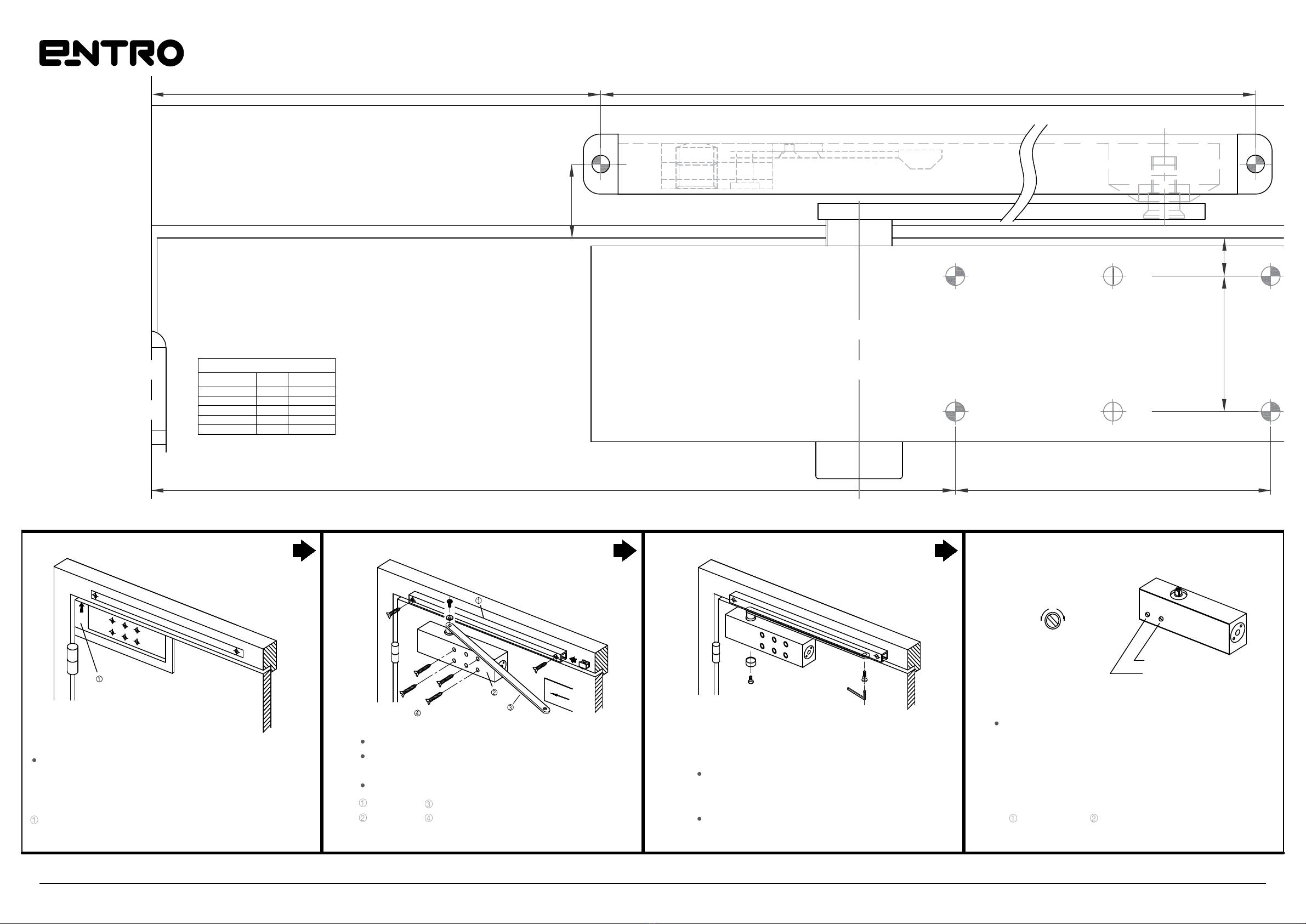
D0701 Closer - Standard Arm
Installation Instructions
D0701 Installation Instructions www.entro.com.au
Strong
DELAY ACTION
BACK CHECK
M5
4.2 2.5
UNDERSIDE
OF FRAME
SPRING POWER SIDE
SPRING POWER ADJUSTMENT
Adjust closer size according to
chart on the right
CC: Counterclockwise
C: Clockwise
*: Factory Pre-set
EN (2-6)
No. Of Turns Size Direction
5
3
3
0*
6
2
3
5
4
6
CC
CC
C
-
C
1 2 3 4
90°
Power +10%
Power -10%
No. 1
No. 1
No. 2
No. 2
SPEED
UP
SLOW
DOWN
SET TO TOP
OF DOOR
Weak
Print Actual Size A3
D0701 Closer - Standard Arm
Installation Instructions
D0701 Installation Instructions www.entro.com.au
Strong
DELAY ACTION
1 2 3 4
90°
Power +10%
Power -10%
No. 1
No. 1
No. 2
No. 2
SPEED
UP
SLOW
DOWN
UNDERSIDE
OF FRAME
SPRING POWER SIDE
SET TO TOP
OF DOOR
Weak
SPRING POWER ADJUSTMENT
Adjust closer size according to
chart on the right
CC: Counterclockwise
C: Clockwise
*: Factory Pre-set
EN (2-6)
No. Of Turns Size Direction
5
3
3
0*
6
2
3
5
4
6
CC
CC
C
-
C
BACK CHECK
M5
4.2 2.5

Print Actual Size A3
D0701 Closer - Parallel Arm
Installation Instructions
D0701 Installation Instructions www.entro.com.au
PARALLEL ARM INSTALLATION FOR ANTI CLOCKWISE OPENING DOOR
FOR CLOCKWISE OPENING DOOR SEE THE BACK PAGE
Closer mounted on door on push side
This template covers regular parallel arm installation for 180° openings
PARALLEL ARM INSTALLATION
FOR ANTI CLOCKWISE OPENING DOOR
(Closer mounted on door on push side)
FOLD HERE
This face to underside
of frame head
Set to underside of frame head
Set this end to
the left of door
Parallel Bracket
4-#12x5/8”
4-#10x2” BACKCHECK NO. 1 CLOSING
Model No. Approximate Door Size (Width)
Interior
850mm
950mm 850mm
1100mm 950mm
1250mm 1100mm
1330mm
2
3
4
5
61250mm
60KG
45KG
Max. Door
Weight
80KG
110KG
150KG
Exterior
Not Recommended
NO. 2 LATCHING
NO. 2
NO. 1
SPEED ADJUSTING VALVE
SPEED
UP
SLOW
DOWN
SPRING POWER ADJUSTMENT
Adjust closer size according to
chart on the left
CC: Counterclockwise
C: Clockwise
*: Factory Pre-set
2-6 Model
No. Of Turns Size Direction
6½
3½
3½
0*
6½
2
3
5
4
6
CC
CC
C
-
C
Print Actual Size A3
D0701 Closer - Parallel Arm
Installation Instructions
D0701 Installation Instructions www.entro.com.au
PARALLEL ARM INSTALLATION
FOR ANTI CLOCKWISE OPENING DOOR
(Closer mounted on door on push side)
4-#10x2”
BACKCHECK
NO. 1 CLOSING
NO. 2 LATCHING
NO. 2
NO. 1
SPEED ADJUSTING VALVE
SPEED
UP
SLOW
DOWN
PARALLEL ARM INSTALLATION FOR CLOCKWISE OPENING DOOR
FOR ANTI CLOCKWISE OPENING DOOR SEE THE BACK PAGE
This template covers regular parallel arm installation for 180° openings
This face to underside
of frame head
SPRING POWER ADJUSTMENT
Adjust closer size according to
chart on the right
CC: Counterclockwise
C: Clockwise
*: Factory Pre-set
2-6 Model
No. Of Turns Size Direction
6½
3½
3½
0*
6½
2
3
5
4
6
CC
CC
C
-
C
Parallel Bracket
4-#12x5/8”
Model No. Approximate Door Size (Width)
Interior
850mm
950mm 850mm
1100mm 950mm
1250mm 1100mm
1330mm
2
3
4
5
61250mm
60KG
45KG
Max. Door
Weight
80KG
110KG
150KG
Exterior
Not Recommended
FOLD HERE
Set to underside of frame head
Set this end to
the right of door
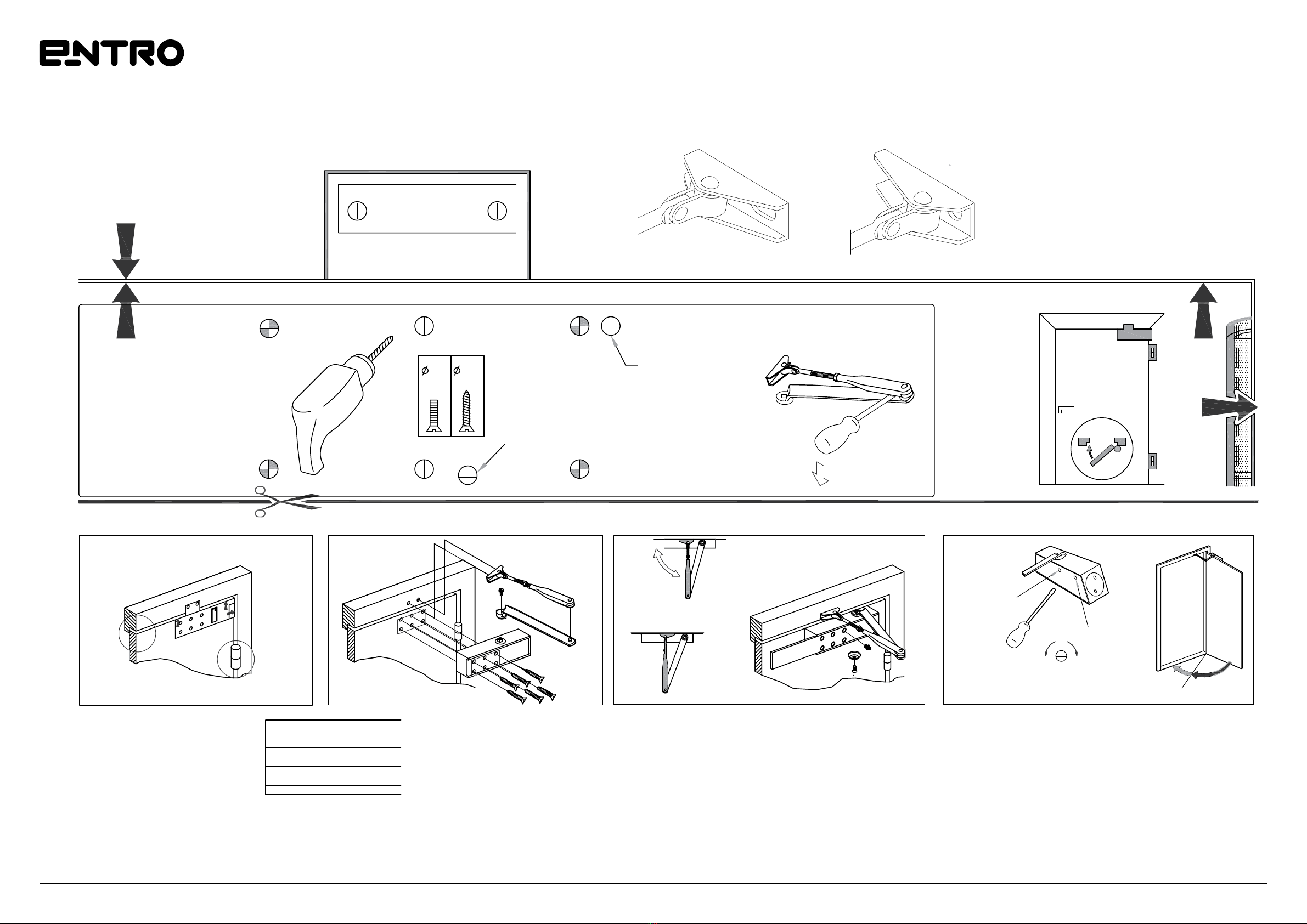
Print Actual Size A3
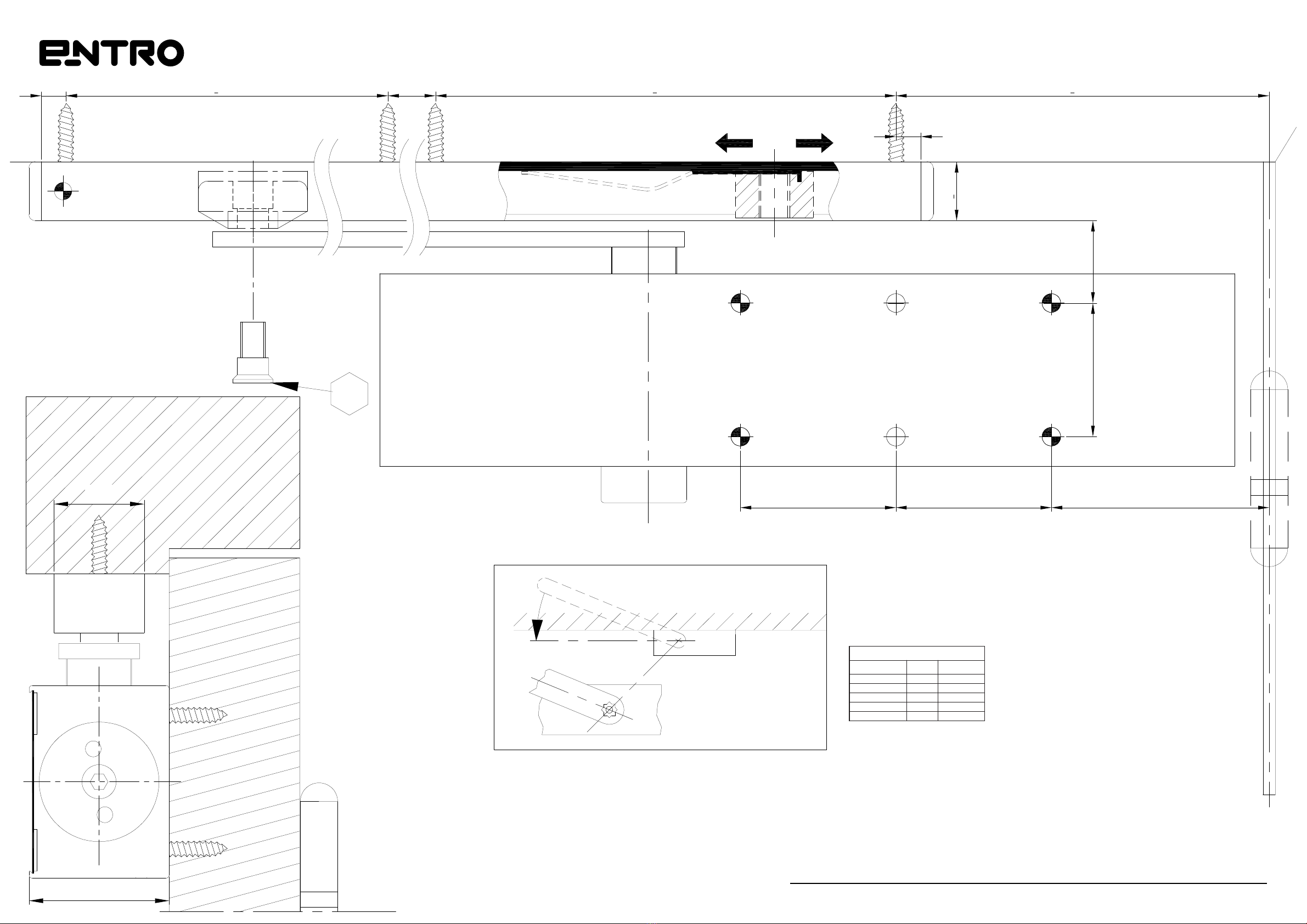
D0701 Closer - Slide Arm
Installation Instructions
D0701 Installation Instructions www.entro.com.au
104 240
39
4-#10x2”
2-#10x2”
470
CAUTION - Pull Side Installation Only
For Push Side Installation Order D0612 Long Slide Rail
143
HOLD - OPEN CLIP (OPTIONAL)SLIDER
Instructions for Installation of the Door Closers (Standard Type)
No.1 CLOSING
No.2 LATCHING
SLOWFAST
Adjust the link length so that the link
makes a right angle with the top jamb,
and fix with the lock nut
FIX PINION CAP TO CLOSER BODY
Determine the installation position of the door closer
place the templet on the closed door and the top
jamb, and make holes in them with a punch or other
proper tool
Templet
Adjust the closing speed.
The door closer closes the door at two different
speeds.
The first speed can be controlled by the No.1
speed adjusting valve, and the second speed, by
the No. 2 speed adjusting valve
CLOSING LATCHING
Fix the link shoe to the top jamb
Fit the lever to the pinion shaft and fix it firmly
with the screw
Mount the closer on the door
Track
Body
Main arm
Mounting screw
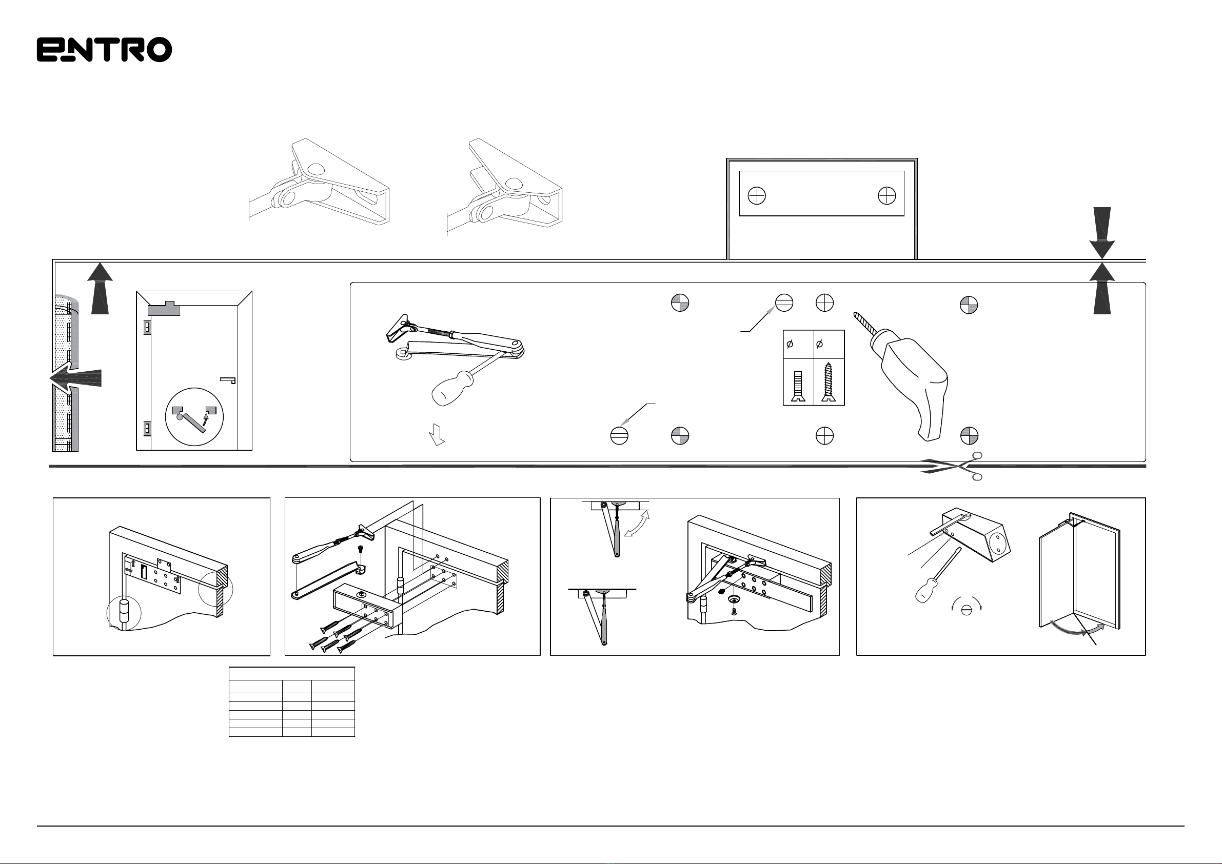
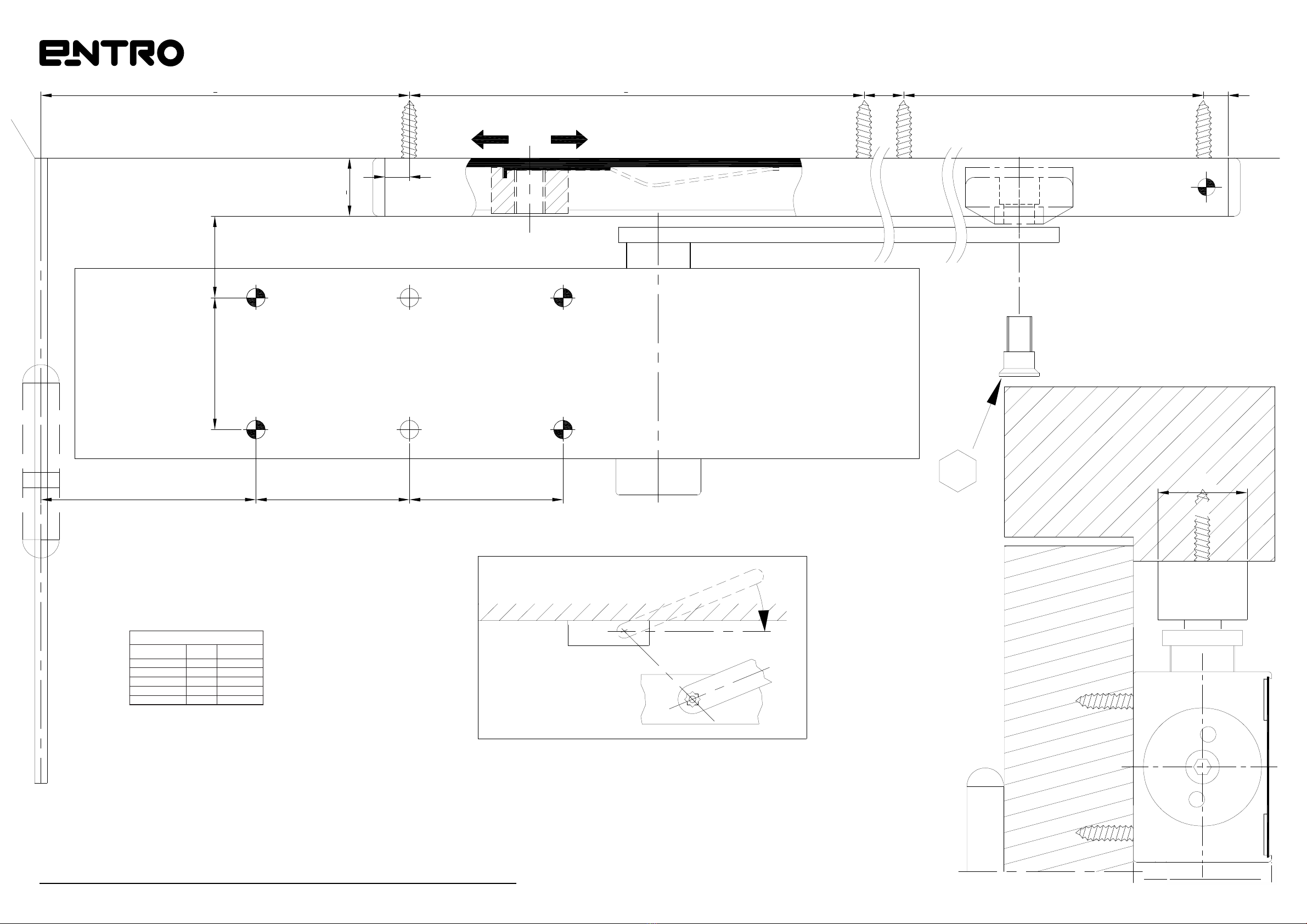
Print Actual Size A3
D0701 Closer - Slide Arm
Installation Instructions
D0701 Installation Instructions www.entro.com.au
CAUTION - Pull Side Installation Only
For Push Side Installation Order D0612 Long Slide Rail HOLD - OPEN CLIP (OPTIONAL)
143
23.5
43
100255
12
470
SLIDER
Instructions for Installation of the Door Closers (Standard Type)
Determine the installation position of the door closer
place the templet on the closed door and the top
jamb, and make holes in them with a punch or other
proper tool
Templet
Fix the link shoe to the top jamb
Fit the lever to the pinion shaft and fix it firmly
with the screw
Mount the closer on the door
Adjust the link length so that the link
makes a right angle with the top jamb,
and fix with the lock nut
FIX PINION CAP TO CLOSER BODY
Adjust the closing speed.
The door closer closes the door at two different
speeds.
The first speed can be controlled by the No.1
speed adjusting valve, and the second speed, by
the No. 2 speed adjusting valve
Track
Body
Main arm
Mounting screw CLOSING LATCHING
SLOW
No.1 CLOSING
No.2 LATCHING
FAST
REGULAR INSTALLATION
FOR CLOCKWISE OPENING DOOR
(Closer mounted on door on pull side)
SPRING POWER ADJUSTMENT
Adjust closer size according to
chart on the bottom
CC: Counterclockwise
C: Clockwise
*: Factory Pre-set
2-6 Model
No. Of Turns Size Direction
5
3
3
0*
6
2
3
5
4
6
CC
CC
C
-
C
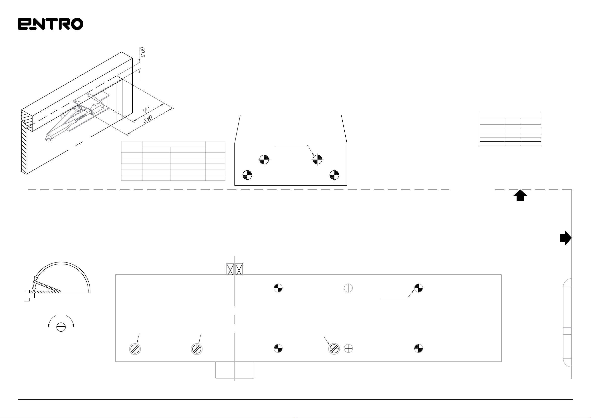
Print Actual Size A3
D0701 Closer - D0612 Long Slide Rail
Installation Instructions
D0701 Installation Instructions www.entro.com.au
SPRING POWER ADJUSTMENT
Adjust closer size according to
chart on the bottom
CC: Counterclockwise
C: Clockwise
*: Factory Pre-set
2-6 Model
No. Of Turns Size Direction
5
3
3
0*
6
2
3
5
4
6
CC
CC
C
-
C
HOLD - OPEN CLIP (OPTIONAL)
CAUTION - PUSH SIDE
INSTALLATION ONLY
Using D0612 Long
Slide Rail
SLIDER
8 148 344 148 120
8
19
26.543
705050
5
29
45
22.5°

Print Actual Size A3
D0701 Closer - D0612 Long Slide Rail
Installation Instructions
D0701 Installation Instructions www.entro.com.au
SPRING POWER ADJUSTMENT
Adjust closer size according to
chart on the bottom
CC: Counterclockwise
C: Clockwise
*: Factory Pre-set
2-6 Model
No. Of Turns Size Direction
5
3
3
0*
6
2
3
5
4
6
CC
CC
C
-
C
CAUTION - PUSH SIDE
INSTALLATION ONLY
Using D0612 Long
Slide Rail
120640
5
22.5°
HOLD - OPEN CLIP (OPTIONAL)
SLIDER
19
26.5
36
43
705050
29
45

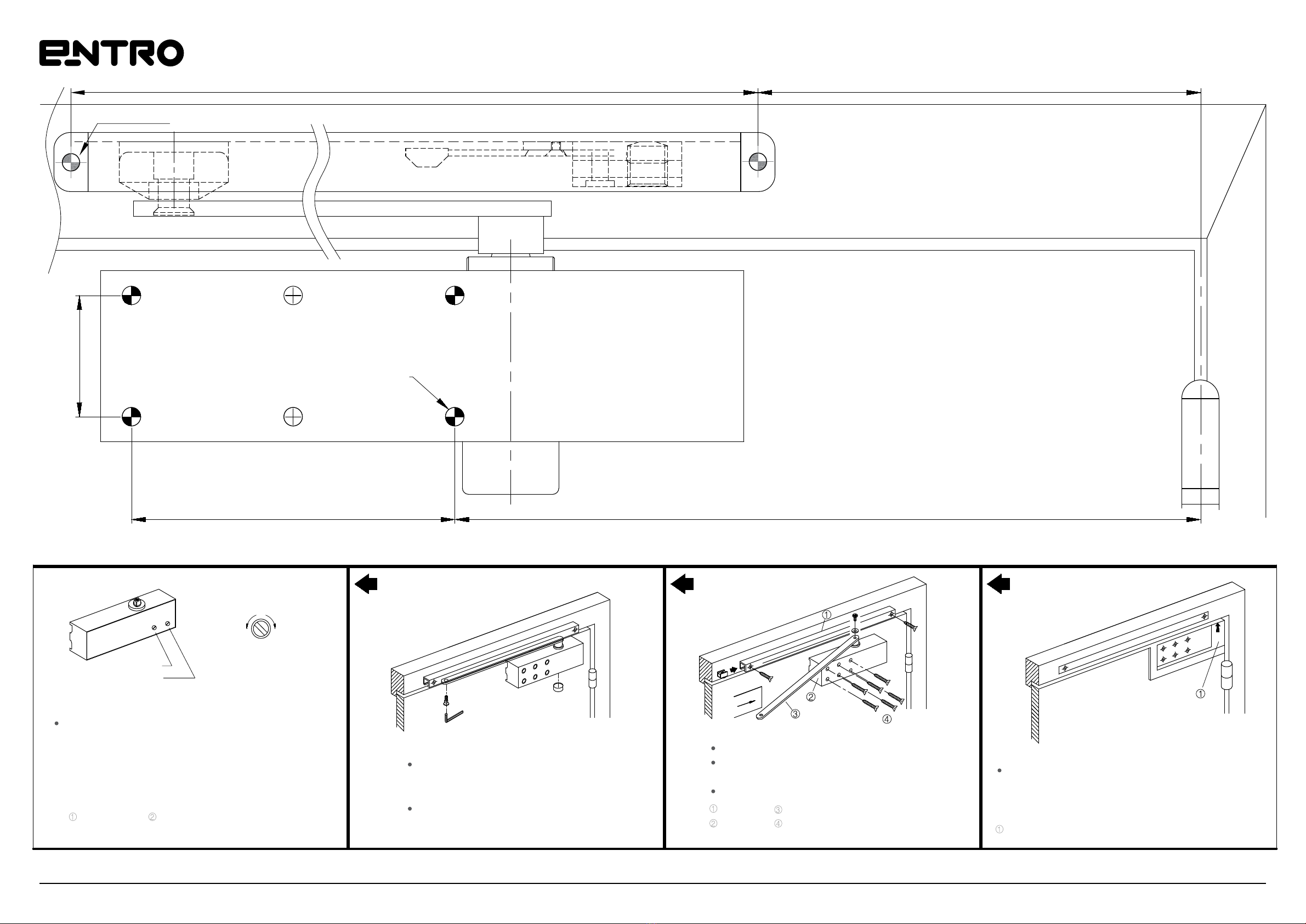
Print Actual Size A3
D0701 Closer - D0612 Long Slide Rail
Installation Instructions
D0701 Installation Instructions www.entro.com.au
SPRING POWER ADJUSTMENT
Adjust closer size according to
chart on the bottom
CC: Counterclockwise
C: Clockwise
*: Factory Pre-set
2-6 Model
No. Of Turns Size Direction
5
3
3
0*
6
2
3
5
4
6
CC
CC
C
-
C
CAUTION - PUSH SIDE
INSTALLATION ONLY
Using D0612 Long
Slide Rail
120 640
5
HOLD - OPEN CLIP (OPTIONAL) SLIDER
19
26.5
36
43
70 5050
22.5°
29
45
Print Actual Size A3
D0701 Closer - D0612 Long Slide Rail
Installation Instructions
D0701 Installation Instructions www.entro.com.au
SPRING POWER ADJUSTMENT
Adjust closer size according to
chart on the bottom
CC: Counterclockwise
C: Clockwise
*: Factory Pre-set
2-6 Model
No. Of Turns Size Direction
5
3
3
0*
6
2
3
5
4
6
CC
CC
C
-
C
CAUTION - PUSH SIDE
INSTALLATION ONLY
Using D0612 Long
Slide Rail
5
HOLD - OPEN CLIP (OPTIONAL) SLIDER
22.5°
29
45
8148344148120
8
26.5
43
19
70 5050
Other manuals for D0701
1
Other ENTRO Door Lock manuals

Popular Door Lock manuals by other brands


Ezviz
Ezviz L2 quick start guide

Salto
Salto XS4 Mini installation guide

Iseo
Iseo Push-Bolt Assembling and maintenance instructions

Assa Abloy
Assa Abloy Corbin Russwin Access 800 9800 TCWI1 Series installation instructions

Assa Abloy
Assa Abloy 81 C Series manual

JCM Technologies
JCM Technologies KEELock quick guide