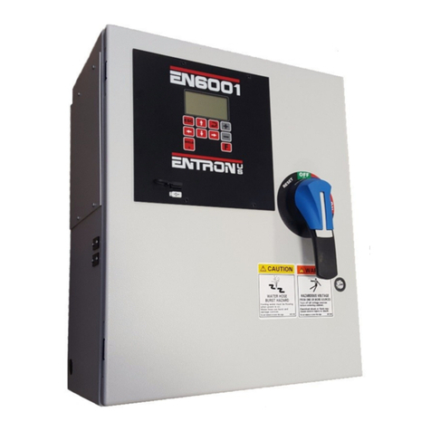
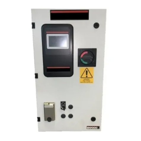
Entron EN1000 series User manual

,16758&7,210$18$/
&
(16(5,(6&21752/6
1(0$7<3($//
0,&52352&(6625%$6('
:HOG6HTXHQFH&RQWUROV
:LWK
6ROLG6WDWH7K\ULVWRU&RQWDFWRUV
:LULQJ'LDJUDP 5&DELQHW
6&DELQHW
7'/6/)&DELQHW
(&DELQHW
(17521&RQWUROV,QF
(DVW5DQG\5RDG
&DURO6WUHDP,OOLQRLV
)$;

Page 1
710228A
CAUTION
READ THIS MANUAL COMPLETELY BEFORE ATTEMPTING
TO INSTALL OR OPERATE THIS CONTROL
(17521&RQWUROV,QF
0,&52352&(6625%$6(':(/',1*&21752/
:,7+62/,'67$7(7+<5,6725&217$&7256
,167$//$7,21$1'23(5$7,210$18$/)25
0RGHO6HULHV(11(0$7\SH$//
(17521&RQWUROV,QFUHVHUYHVWKHULJKWWRDOWHUWKHFRQWHQWVRI
WKLVPDQXDOZLWKRXWSUHYLRXVQRWLFH
(17521&RQWUROV,QF
&DURO6WUHDP,OOLQRLV

Page 2
7$%/(2)&217(176
7$%/(2)&217(176
*(1(5$/'(6&5,37,21
67$1'$5')($785(6
(1&21752/3$1(//$<287
&21752/)81&7,216
352*5$00,1*3$5$0(7(566(/(&7,21
7,0('3$5$0(7(56
27+(5352*5$00$%/()81&7,216
,1,7,$7,217:267$*(3,/27
,1,7,$7,216,1*/(67$*(3,/27
,1,7,$7,21%($723(5$7,21
27+(5&+$5$&7(5,67,&6
12192/$7,/(0(025<(5525
92/7$*(352*5$00,1*
)86,1*
&86720(57(50,1$/675,3',$*5$06
&86720(57(50,1$/675,3&211(&7,216
35,0$5<:,5,1*72:(/',1*&217$&725
&22/,1*5(48,5(0(176)25&217$&7256
,167$//$7,21',$*5$066&$%,1(7
,167$//$7,21',$*5$06(&$%,1(7
,167$//$7,21',$*5$067'/&$%,1(7
0(&+$1,&$/02817,1*',$*5$067(&$%,1(7
*(1(5$/23(5$7,1*,16758&7,216
,1752'8&7,2172352*5$00,1*7+((1
*(1(5$/352*5$00,1*
352*5$0/2&.287
(;7(1'(')81&7,216
6($0:(/',1*
6&+('8/(6(/(&7,21,17(;7$1'$17,7,('2:1
$9&
&/($5$//)81&7,216
7(03(5$785(/,0,76:,7&+%$&.67(3
352&(662873876
,1,7,$7,2102'(6
0$18$/32:(5)$&725352*5$00,1*
32:(5)$&7250($685,1*
23(5$7,1*02'(6
1215(3($7
5(3($7
&+$,1('02'(
68&&(66,9(02'(

Page 3
710229
7$%/(2)&217(176FRQWLQXHG
6/23(02'(&21752/
126/23(
836/23(
'2:16/23(
6(77,1*6/23(%27720&855(17
9$/9(02'(6
$33/,&$7,216)25*('(/$<
:(/'&855(17'(/$<
08/7,3/(6&+('8/(23(5$7,21
(5525&2'(6
7528%/(6+227,1*
:$55$17<$1'6(59,&(

Page 4
*(1(5$/'(6&5,37,21
The EN1000 is a microprocessor based resistance welding control. It can store as many as
11 parameters in each of 50 unique schedules. These are held in non-volatile memory for
storage.ItcanperformUpSlope,DownSlope,Quench,Temper,Pulsation,Seam,andSpot,
all of which can be combined to provide for any possible welding schedule imaginable. In
addition, schedules can be chained together to provide more complex welding sequences.
Despite the seemingly complicated possible welding schedules, the EN1000 is simple to
program and operate. Versatility is built in to allow the individual to configure the control
to any application.
This control provides an accurate, predetermined welding schedule for a specific number of
cycles upon an external command. The initiation command is usually provided by the
closure of a normally open switch, located on or installed as part of the welding machine,
which starts the welding interval. The initiation switch need not remain closed for the
duration of the weld, but must be opened after the welding interval is completed in order to
re-initiate the control. After a weld has been started, the control cannot be re-initiated until
the previous weld is completed. All control functions are performed digitally.
67$1'$5')($785(6$//02'(/6
',*,7$/3+$6(6+,)7&855(17&21752/ varies the current from 0 to 99% of
maximum and is adjusted in 1% RMS current steps by front panel Push Buttons with direct
reading LED displays. When the control is used with ignitron tube contactors, do not set
below 40% for 240 volt operation, or 20% for 480 volt operation.
)81&7,21&<&/(&28176(/(&7 circuit uses front panel Push Button switches with
direct reading LED displays to select the function intervals absolutely in 1 cycle steps.
"Timing" is achieved by counting each cycle of the line current directly. This method of
"timing" allows this control to be used on either 50 or 60Hz power without special
adjustments.
127(12$'-8670(17LVUHTXLUHGIRUSRZHUIDFWRURUWLPLQJWR
FKDQJHIURPWR+]RSHUDWLRQ
35(6685(6:,7&+),5,1* is a terminal strip connection which allows the control to
be initiated from a pressure switch closure. Remove the jumper from TS1-PS1 and
TS1-GND and connect pressure switch leads. Pressure switch is not furnished with control.
('(/$<('),567+$/)&<&/(),5,1* delays the first half-cycle of each weld
sequence by 87(. The purpose of the 87(delay is to prevent the build-up in the welding
transformer of a DC component which may be damaging when wound core (hypersil)
transformers are used.

Page 5
710230
(0(5*(1&<6723 - This is a terminal strip connection that allows all control functions
toberesetuponopeningoftheEMERGENCYSTOP switch. Control willnotbere-initiated
automatically upon release of the switch and must be re-initiated through the normal
initiation circuit. Remove the jumper from TS1-ES1 and TS1-GND and install a normally
closed switch. EMERGENCY STOP switch is not furnished with control.
9$/9(&21752/75$16)250(5 - This transformer provides the necessary voltage
forpowering the weldingmachine solenoid valve(s).Input voltage maybe either 240or 480
VAC (see CUSTOMER WIRING DIAGRAM). Output is 115 VAC (Optional low voltage
transformer for certain operations provides a 24/48 VAC output). 150 VA transformer is
standard in R, T, and NEMA enclosures (250 VA transformer optional). A 50 VA
transformer is provided in the S style cabinet. SEE CAUTION BELOW.
&$87,21
When external valve power is used (24-240 VAC). Valve transformer must
be disconnected at TS3-VL1 and TS3-VL2. Caution must be used to
properly insulate the wires from X1 and X2 leads after removing from TS3.

Page 6
(1&21752/3$1(//$<287
FIGURE 1
:(/'12:(/'6:,7&+ ,1',&$725/('6/23(02'()81&7,21
,1',&$725/('12:(/'02'( ,1',&$725/('6/23(&2817)81&7,21
,1',&$725/(':(/'02'( ,1',&$7251(210$,132:(5
'$7$',63/$< ,1&5(0(176&+('8/(6(/(&76386+%87721
,1&5(0(17'$7$6386+%877216:,7&+ ,1&5(0(176&+('8/(6(/(&76386+%87721
,1&5(0(17'$7$6386+%877216:,7&+ 6&+('8/(6(/(&7',63/$<
,1',&$725/('648((=()81&7,21 ,1',&$7251(21:(/'
,1',&$725/(':(/')81&7,21 352*5$0/2&.2876:,7&+
,1',&$725/('3(5&(17&855(17)81&7,21 ,1',&$725/('&21752/,123(5$7(02'(
,1',&$725/('+2/')81&7,21 352*5$023(5$7(386+%87721
,1',&$725/('2)))81&7,21 ,1',&$725/('&21752/,1352*5$002'(
)81&7,216(/(&7,21386+%877216:,7&+ ,1',&$725/('9$/9(
,1',&$725/(',038/6(6)81&7,21 (17(5386+%877216:,7&+
,1',&$725/('&22/)81&7,21 ,1',&$725/('9$/9(
,1',&$725/('9$/9(02'()81&7,21 ,1',&$725/('9$/9(
,1',&$725/('&<&/(02'()81&7,21
*For operator convenience, the codes for these mode and selection functions are printed on
the left side of the control panel, adjacent to Push Buttons (1) and (26).

Page 7
710232A
&21752/)81&7,216 - See Figure 1, CONTROL PANEL LAYOUT.
32:(521/,*+7 - The red POWER (19) lamp on the light panel, at the top of the R
cabinet door or bottom of the S cabinet dialplate, indicates when power is applied to the
control.
9$/9(/('6 - The three LED'S (28 & 30 & 31) indicate, in the operating mode, when
the solenoid valves are activated in the control program. In the PROGRAM Mode these
same indicators indicate the valve that will be used by the selected valve code for the
selected schedule.
:(/'/,*+7 - The white WELD lamp (23) on the light panel at the top of the control door
or bottom of the S cabinet dial plate, is connected directly across the welding transformer
and will light when voltage is present at the welding transformer. The brilliance of the white
WELD lamp is an indication of the programmed PERCENT CURRENT and therefore,
provides a visual indication of the percent of RMS voltage supplied to the welding
transformer.
352*5$023(5$7(6(/(&7,21: Push Button (26) and LED indicators (27) and (25)
and PROGRAM LOCKOUT key switch (24).
Every time the PROGRAM/OPERATE Push Button (26) is pressed the control will toggle
between the PROGRAM (LED 27) and OPERATE (LED 25) modes.
PROGRAM mode is the mode in which the individual schedules can be entered or
modified. The different parameters of times, valves, etc. can be changed only in the
PROGRAM MODE.
OPERATE mode is the normal operating mode for the control and is the only mode
in which the control can be initiated for a weld schedule. When the control is in
OPERATE mode, and not initiated, the control is in a "Ready" or Operational state.
NOTE:A PROGRAM LOCKOUT (24) key switch can be ordered as a factory
installed option. It may also be added later by the customer, if desired. To install the
key switch, remove the hole plug from the lower left corner of the front panel and
mount the switch using the nut provided. Plug the wires from the switch onto the
mating 2 prong connector on the back of the control circuit board.
In "S" cabinets, mounting the key switch will be easier if the front panel and control
circuitboardassemblyisremovedfromtheenclosure.RemovethePOWER(19)and
WELD (23) lights and disconnect the electrical connectors from the back of the
control circuit board. Remove the four (4) mounting screws from the front panel and
lift it off of the enclosure.
To select the PROGRAM MODE using the PROGRAM LOCKOUT Switch, the
key must be rotated 45 degrees clockwise and held against spring pressure while the
PROGRAM/OPERATEPush Button ispressed.TheOPERATE LED will nowturn
off and the PROGRAM LED will turn on, indicating programmability of all
functions. Pressing the PROGRAM/OPERATE Push Button again will return the
control to the OPERATE Mode without the necessity of rotating the key.

Page 8
6&+('8/(180%(56(/(&7,21: Displayed by (22).
There are two possible ways to select the SCHEDULE to be initiated. Schedules can be
selected internally or externally.
INTERNAL: If EXTENDED FUNCTION, SCHEDULE SELECT [SS] is set to
INTERNAL [00], use Push Button switches (20) and (21) to select the desired
SCHEDULE.Push Button switch (21) increments the10'sdigitbyoneand Push Button
switch (20) increments the 1's digit by one. When the maximum number is reached for
either digit, that digit resets to zero.
EXTERNAL: If EXTENDED FUNCTION, SCHEDULE SELECT [SS] is set to
EXTERNAL [01], use the binary combination of TS1-FS7/SS1, TS1-FS11/SS3, to
select the desired SCHEDULE (See section 5.3 CUSTOMER TERMINAL STRIP
CONNECTIONS and EXTENDED FUNCTIONS section 7.3.
352*5$00,1*3$5$0(7(56(/(&7,21: Push Button (12), LEDs
(7-11 & 13-18).
Using Push Button switch (12) any function can be selected. Use Push Button to shift the
lighted (active) selection down one LED. If no LED is lit, then EXTENDED FUNCTIONS
have been selected. This is necessary when programming the EXTENDED FUNCTIONS
(See section 7.3 EXTENDED FUNCTIONS). EXTENDED FUNCTIONS can be reached
simply by pressing Push Button (12) until all the LEDs (7-11 & 13-18) are off.
7,0(3$5$0(7(56 (Count Functions).
SQUEEZE ........................ 0to99cycles (Programmed 00 = 0 cycle)
WELD/HEAT ..................... 0to99cycles (Programmed 00 = 0 cycle)
HOLD ........................... 0to99cycles (Programmed 00 = 0 cycles)
OFF ............................. 0to99cycles (Programmed 00 = 0 cycle)
IMPULSES ....................... 1to99cycles (Programmed 00 = 1 cycle)
COOL ............................ 0to99cycles (Programmed 00 = 0 cycles)
SLOPE COUNT .................... 0to99cycles (Programmed 00 = 0 cycles)
648((=(&2817(7) - The time duration for the electrodes to close on the work and
build up pressure before WELD Count begins.
:(/'+($7&2817(8) - The time duration after SQUEEZE COUNT or closure of a
pressure switch that current will flow through the welding transformer. HEAT count (the
time duration that welding current flows in one impulse) is programmed by WELD Count
in impulse welding.
+2/'&2817(10) - The time duration after WELD Count that the welding electrodes
remain in contact with the work to allow the weld nugget to congeal.
2))&2817(11) - In the Repeat mode, the time duration between HOLD Count and
SQUEEZE Count to allow the work to be repositioned.
&22/&2817(14) - The time duration in multiple impulse welding between successive
HEAT impulses.
NOTE: NO ADJUSTMENT is required for power factor or timing to
change from 60 to 50 Hz operation.

Page 9
710232A
6/23(&2817(18) - The number of cycles during which the percent current increases
or decreases cycle by cycle to achieve a slope function (gradual increase or decrease in
current).
27+(5352*5$00$%/()81&7,216
,038/6(6 (13) - In multiple impulse welding this counter counts the number of
predetermined Heat Impulses. The duration of the Heat Count is determined by the Heat
Count Selector.
3(5&(17&855(17 (9) (Phase Shift) 0 to 99% (Adjustable in 1% RMS current steps)
NOTE: For operator convenience, the following mode and function selection codes are
printed on the upper left corner of the Control panel, adjacent to Push Button (1).
6/23(02'( (17) - The type of slope function is determined by the code programmed
into this function as follows:
CODE 00: NO SLOPE during WELD Time. SLOPE control inoperative.
CODE 01: UP SLOPE
CODE 02: DOWN SLOPE
&<&/(02'( (16) - The manner in which the control performs schedules is determined
by the code programmed into this function as follows:
NOTE: For operator convenience, the following mode and function selection codes are
printed on the lower left corner of the Control panel, adjacent to Push Button (26).
CODE 00: NON-REPEAT MODE. In NON-REPEAT mode the control can be
initiated for only one sequence.
CODE 01: REPEAT MODE. In REPEAT mode, after initiation, the control
internally re-initiates as long as the initiation switch is maintained closed.
CODE 02: CHAINED MODE. In the CHAINED mode several schedules can be
"chained" together so that several consecutive schedules can be sequenced from one
initiation.
CODE03:SUCCESSIVEMODE.IntheSUCCESSIVEmodeseveralschedulescan
be sequenced successively upon separate initiation.

Page 10
9$/9( 02'( (15) - The three solenoid valves are activated based on the code
programmed as shown in Table 1 below.
7$%/(
CODE TS1-SV1 TS1-SV3 TS1-SV5
--------------------------------------------------------------------
00
--------------------------------------------------------------------
01 X
--------------------------------------------------------------------
02 X
--------------------------------------------------------------------
03 XX
--------------------------------------------------------------------
04 X
--------------------------------------------------------------------
05 XX
--------------------------------------------------------------------
06 XX
--------------------------------------------------------------------
07 XX X
--------------------------------------------------------------------
When in the PROGRAM mode and selection of a valve code is being
made, the valve LED indicators (28,30,31) will indicate the selected
valve /s (the valve /s output will not be energized while in program
mode).
NOTE: The valve code indicated above can be altered for different
features such as PROCESS OUTPUT. See section 7.3 EXTENDED
FUNCTIONS.
Change of '$7$',63/$<: Push Buttons (5) and (6), Display (4).
Change of the data displays can only be performed in PROGRAM MODE. Use Push Button
switches (5) and (6) to change the display. Push Button (5) increments the 10's digit by one
andPushButton(6) incrementsthe1'sdigitby one.Wheneither digitreachesthemaximum,
the DATA display resets to zero. When the desired data is displayed, data is entered by Push
Button switch (29).
(17(56ZLWFK: Push Button switch (29).
This switch is used to enter the data displayed in the DATA Display (4) into the non-volatile
memory.

Page 11
710233A
,1,7,$7,217:267$*(3,/27
This control may be initiated by the closure of a two stage pilot. First stage is connected to
TS1-FS1 and TS1-GND, second stage is connected to TS1-FS3 and TS1-GND. The first
stage only activates the selected solenoid valve for the selected schedule, and does NOT
initiate a sequence. Once the control is initiated, via FS3, FS1 need not remain closed. The
initiation circuit is automatically clamped to prevent re-initiation until after the control has
completed its sequence. In the REPEAT MODE the control will continue to sequence as
long as the initiation remains closed.
,1,7,$7,216,1*/(67$*(3,/27
This control may be initiated by the closure of a single stage pilot. The pilot switch is
connected between TS1-FS3 and TS1-GND terminals. Once the control is initiated, the
switch need not remain closed. The initiation circuit is automatically clamped to prevent
re-initiation until after the control has completed the sequence. No connection is made to
TS1-FS1.
See also section 5.2 CUSTOMER TERMINAL STRIP DIAGRAMS.
,1,7,$7,21%($723(5$7,21
This control can be converted to BEAT OPERATION by use of the EXTENDED
FUNCTIONS. See section 7.10. Several different modes are available.
27+(5&+$5$&7(5,67,&6
:(/'12:(/'6:,7&+ (1) and LED INDICATORS (2,3)
When the control is in NO WELD, the NO WELD LED (2) is illuminated. This allows the
control to be initiated without passing current through the welding transformer. When the
WELD LED (3) is illuminated, the SCR contactor will pass current through the welding
transformer during the programmed weld time. To toggle between these two modes simply
depress the WELD/NO WELD Push Button (1).
35(6685( 6:,7&+: If the pressure switch is not activated (open), the control will
advancethroughSQUEEZETimeandwaituntilthepressureswitchclosesbeforeadvancing
to WELD Time. The SQUEEZE LED will begin flashing at the end of SQUEEZE Time and
continue until the Pressure Switch closes. When the Pressure Switch closes, the control will
beginWELD Time andcomplete the sequence.It may bedesired to setSqueeze count to00.
This allows the weld sequence to begin immediately upon closure of the Pressure Switch.
If the Pressure Switch interrupts the sequence for an extended period the display will flash
the ERROR CODE # 15. This error will not terminate the weld sequence. Once the Pressure
Switch closes the sequence will continue on to weld time and complete the sequence.
See also section 5.3 CUSTOMER TERMINAL STRIP CONNECTIONS.
NOTE: Jumper TS1-PS1 and TS1-GND if pressure switch is not used. A Pressure Switch
is not furnished with the control.

Page 12
&217$&7257(03(5$785(/,0,76:,7&+: If the Temperature Limit Switch is
activated (open), the control cannot be initiated. The initiation will remain inactive until the
Temperature Limit Switch cools (resets). If the Temperature Limit Switch is activated
(opened) during WELD Time, the firing pulses to the contactor will continue until the end
of WELD Time. Then, HOLD and OFF time will follow. A new sequence cannot be
initiated as above, until the Temperature Limit Switch cools and resets. The DATA Display
will display an ERROR Code 01 in DATA Display (4) until the Temperature Limit Switch
recovers its normally closed state. At this time, the DATA Display will again display the
data stored in the currently selected Function. See TROUBLE SHOOTING section 13.1.
If during CONTINUOUS or INTERMITTENT SEAM WELDING, the Temperature Limit
Switch is activated, it is the same as opening the initiation. If the Temperature Limit Switch
is opened, the Weld Schedule will end. A flashing ERROR Code 01 will appear in the
DATA Display (4) when the Temperature Limit Switch opens.
Depending upon machine requirements a flow switch can either be substituted for a
Temperature Limit Switch or wired in series with the Temperature Limit Switch. The
operation as described above will still be similar.
NOTE: This feature is a programmable feature and is factory programmed to default to a
Temperature Limit Switch. For other uses of TS1-TLS1/AUX1 see section 7.8
TEMPERATURE LIMIT Switch / Back Step.
NOTE: Jumper TS1-TLS1/AUX1 and TS1-GND if the Temperature Limit Switch is not
used. Temperature Limit Switch supplied standard, with 300,600 and 1200 AMP SCR
Contactors and optionally with 1800 and 2200 AMP SCR Contactors.
(0(5*(1&<6723:Thisisaterminalstripconnectionwhichallowsallcontrolfunctions
to be reset upon opening of the Emergency Stop switch. The control can not be re-initiated
automatically upon release of the switch and must be re-initiated through the re-closure of
the pilot circuit. While in the Emergency Stop condition, the control will flash an ERROR
Code "E.S." in the DATA Display (4) until the condition has been cleared.
NOTE: Jumper TS1-ES1 and TS1-GND if the Emergency Stop Switch is not used.
Emergency Stop Switch is not supplied with the control.
23(5$7,1*&21',7,216
Temperature Range: 0(C to 70(C (32(F to 158(F).

Page 13
710234
92/7$*(352*5$00,1*
THIS WELDING CONTROL IS A MULTI-VOLTAGE UNIT WHICH CAN BE
CHANGED FROM ONEVOLTAGE TO ANOTHER BY RE-ARRANGING JUMPERS
ON THE TERMINAL STRIP FOUND INSIDE THE UNIT. IF THE CONTROL IS
USED ON A VOLTAGE OTHER THAN THE ONE FOR WHICH IT IS WIRED,
SERIOUS DAMAGE CAN RESULT.
It is possible to operate the EN1000 control at 208, 240, 380, 480, and 575 VAC. When a
380 or 575 VAC main is desired, please consult the factory. When the control is converted
from one line voltage to another, there are three changes required.
1. Control Transformer: Jumpers on TS1-L2/CTH4, CTH2, CTH3, and L1/CTH1
must be configured to match the line voltage.
2. Sense Transformer: Jumpers on TS1-H4, TS1-H2, TS1-H3, and TS1-H1 must be
configured to match the line voltage.
3. Valve Transformer: Jumpers on the valve transformer H1, H3, H2, and H4 must
be configured to match the line voltage.
230 Volt Operation Jumpers
Customer Terminal Strip TS1:
Jumper H1/H3 and H2/H4
CTH1/CTH3 and CTH2/CTH4
Valve Transformer:
Jumper H1/H3 and H2/H4
460 Volt Operation Jumpers
Customer Terminal Strip TS1:
Jumper H3/H2
CTH3/CTH2
Valve Transformer:
Jumper H3/H2
&$87,21
3529,'($*22':$7(53,3(*5281'$77+(*5281'
/8*/2&$7(',17+(5($52)7+(&21752/&$%,1(7
&$87,21
:+(17+(:(/',1*&21752/$1'25:(/',1*0$&+,1(:$6
6+,33('7+(92/7$*($7:+,&+,7:$66(7:$60$5.('
217+(7$*$77$&+('727+(&21752/7(50,1$/%/2&.

Page 14
NOTE:Whether valve power is supplied by the Valve transformer or by an external valve
power supply, the maximum current that can be switched by the firing board is 1
AMP per valve. If more current is desired, the valve circuit should be wired to a
relay having a suitable contact rating to switch the desired valve. For more
information, refer to CUSTOMER WIRING DIAGRAM.
)86,1*
CONTROL FUSE- This fuse, a BBS 6/10 AMP, is used to protect the control circuits. The
fuse holder is located in the upper left corner of the contactor door
opening or within the S cabinet.
VALVE FUSE- These fuses, a 2AG 1 AMP, are used to protect the valve circuits. The
fuses are located on the TERMINAL STRIP PCB, PCB2 Assembly
Number 410319 or 410319-001.
IGNITOR FUSES- (Supplied with ignitron tube retrofit controls only). These two fuses,
BAF 6 AMP, are used to protect the ignitor circuits to the ignitron
tubes. The fuse holders are located on the IGNITRON FIRING
BOARD MODULE PCB3 Assembly Number 410318.
INSTALL PROPERLY SIZED FUSES IN SERVICE
DISCONNECT SWITCH. CHECK WELDING MACHINE
MANUFACTURER'S RECOMMENDATIONS.
&$87,21
:KHQH[WHUQDOYDOYHSRZHULVXVHG9$&9DOYHWUDQVIRUPHUPXVW
EHGLVFRQQHFWHGDW769/DQG769/&DXWLRQPXVWEHXVHGWR
SURSHUO\LQVXODWHWKHZLUHVIURP;DQG;OHDGVDIWHUUHPRYLQJIURP76
'$1*(5
92/7$*(635(6(17,17+,6&21752/&$1&$86(6(9(5(
25)$7$/,1-85<'2127&+$1*()86(6:,7+7+(32:(5
2186(21/<7+(7<3(2))86(63(&,),('720$,17$,1
6$)(23(5$7,21

Page 15
710235A
&86720(57(50,1$/675,3',$*5$06
TERMINAL STRIP TS1/PCB1
SEE CUSTOMER WIRING DIAGRAM 421189 R/T CABINET OR 421180 S CABINET

Page 16
TERMINAL STRIP TS1
SEE CUSTOMER WIRING DIAGRAM 421189 R/T CABINET OR 421180 S CABINET

Page 17
710236A
+22.83(;7(51$/,*1,752178%(&217$&725
SEE CUSTOMER WIRING DIAGRAM 421189 R/T CABINET OR 421180 S CABINET

Page 18
+22.83(;7(51$/6&5&217$&725
SEE CUSTOMER WIRING DIAGRAM 421189 R/T CABINET OR 421180 S CABINET

Page 19
710237A
&86720(57(50,1$/675,3&211(&7,216
See diagram on page 15.
TS1-FS1 Used to connect one side of the First Stage of a two Stage Pilot Switch.
Use a single pole, normally open, momentary type Switch. Connect the
First Stage of a TWO Stage pilot Switch between TS1-FS1 and
TS1-GND terminals.
TS1-GND Used as the common connection point for most all of the other terminal
strip connections. There are six GND terminals provided on TS1.
TS1-FS3 Used to connect one side of a Single Stage Pilot. Connect a Single Stage
Pilot between TS1-FS3 and TS1-GND terminals. Use a single pole,
normally open, momentary type switch.
Used to connect one side of a two Stage Pilot. Connect the Second Stage
of a two Stage pilot to TS1-FS3 and TS1-GND terminals. Use a single
pole, normally open, momentary type switch.
WheninitiatedviaTS1-FS3 the weld control will begin from the schedule
that is displayed in the SCHEDULE Display.
TS1-FS7/SS1 Used to connect one side of the second Single Stage Pilot for DUAL
SCHEDULE operation. Connect a Single Stage Pilot between TS1-FS7
and TS1-GND terminals. Use a single pole, normally open, momentary
type switch.
When initiated via TS1-FS7/SS1 the weld control will begin from
SCHEDULE 10 .
Terminal TS1-FS7/SS1 can also function as an External Schedule Select.
Terminals TS1-FS7/SS1 and TS1-FS11/SS3 become External Schedule
Selects when programed via the EXTENDED FUNCTIONS [SS],
EXTERNAL [01]. Use a single pole normally open switch connected to
TS1-FS7/SS1 as shown by the sketch in section 7.5. This switch can now
be used, along with TS1-FS11/SS3 as pointers to one of 4 schedules.
TS1-FS3 is used to then initiate the schedule pointed to. See TABLE 1 in
next connection point TS1-FS11/SS3, (Page 20).
CAUTION
A JUMPER IS NOT REQUIRED ON TS1-FS1 TO TS1-GND WHEN A
TWO STAGE FOOT SWITCH IS NOT USED
Other manuals for EN1000 series
2
Table of contents
Other Entron Control Unit manuals
Popular Control Unit manuals by other brands
Toro
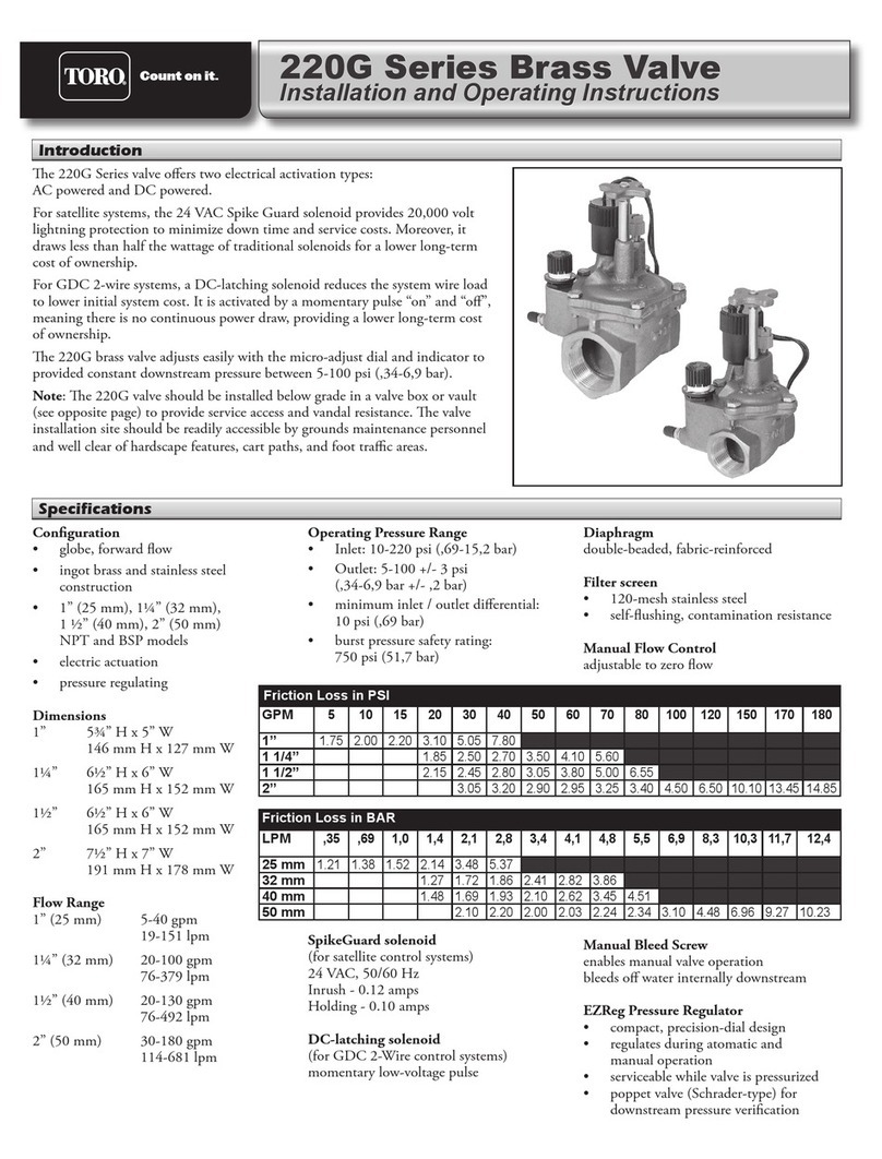
Toro 220G Series Installation and operating instructions
IFM
IFM SmartLine AC3218 operating instructions
Viadrus
Viadrus S.Control Touch Manual for operation
Dynamic Engineering
Dynamic Engineering PMC-BiSerial-III HW2 user manual
Polycom
Polycom SoundPoint IP 670 quick start guide

Eaton
Eaton Eaton 5PX Advanced user's guide
