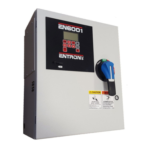
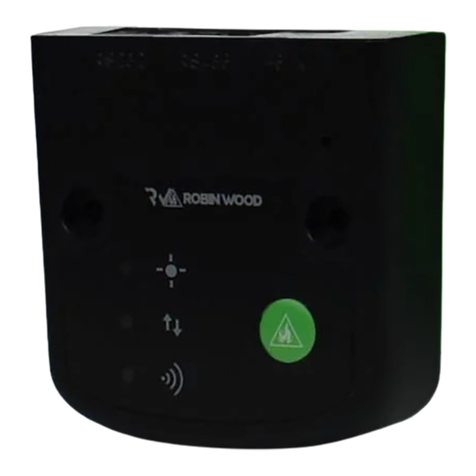
Entron EN6001 User manual

1
ENTRON Controls, LLC. 700230D 1
ENTRON Controls, LLC.
1402 S. Batesville Road
Greer, SC 29650
Phone: 864.416.0190
fax: 864.416.0195
www.entroncontrols.com
User Manual
700230D: Intended for use with rmware version 5.0 and higher

2
ENTRON Controls, LLC. 700230D 2
1.0 Introduction
1.1 Features ..…………………................................................................. 3
1.2 Reference Documents ..………………………………………………… 4
1.3 Specifications ……………………………………………………………. 5
2.0 Safety
2.1 Cooling Water ……………………………………………………………. 6
2.2 Warnings and Labels ……………………………………………………. 7
3.0 Quick Start
3.1 Install and Setup ……...........................................……………………. 9
4.0 Wiring
4.1 Wiring Diagram …………………………………………………………. 11
4.2 Discrete I/O ………………………………………………………………. 13
4.3 Wiring for AC Option …..………………………………………………… 17
5.0 Programming
5.1 Keypad Functions …………..…………………...……..………...……... 20
5.2 Menu Navigation ………………………………………………...………. 21
5.2.1 Status Screens ………………………………...……………... 22
5.2.2 Main Menu Screens ……………………………………..…… 26
5.2.3 Setup Menu Screens ……………………………...…………. 39
5.2.4 Other Screens ………………………………….…………….. 51
5.3 Timing Cycles ...…………………………………………………………. 54
5.3.1 Worksheets ……………………………………………………. 57
5.4 I/O Programming …………………….…………………………………… 59
6.0 Troubleshooting
6.1 Error Codes ………………………………………………………………. 62
6.2 Non-Error Code Issues ..………………………………………..………. 68
6.3 Noise Suppression ………………………………………………………. 71
6.4 Warranty and Service Policy ….……………………………….……….. 72
Table of Contents

3
ENTRON Controls, LLC. 700230D 3
1.1 Features
FEATURES:
• Calibrated constant current regulaon; Primary / Secondary feedback
• Current monitoring with high, low, and pre-limits
• Up to 64 programs (internal or 16 external selecon)
• On Timer Membrane Keyboard with backlit 128x64 (8 lines) LCD graphic display
• Six (6) inputs and four (4) outputs with output protecon on CPU
• Electrode management funcons, including stepping, p-dressing and preset curves
• Welding programs may be linked together for complex spot schedules (chained or successive)
• Refresh rmware through USB device
• Load/export control sengs from/to USB device
• AC 60/50 Hz welding supported
• Spot / Pulsaon / Seam welding / Flash or Bu welding / Brazing
• Mulple weld intervals plus pulsaon, upslope and downslope
• Air-over-oil gun operaon
• Retracon – maintained, and momentary
• Water Saver (contactor mer)
• Shorted contactor detecon
OPTIONS :
• Program Lockout (key switch)
• Operaon Mode Switch (Program Lockout and Weld/No Weld)
• Error Reset Switch
• Oponal plug-in Ethernet card provides PLC compability via MODBUS and Ethernet/IP for remote I/O (ENLink)
• AC Valve outputs
• Interlocking Door Solenoid (IDS)
• Full Phase Isolaon (FPI)
• Water Flow Switch (WFS)
• Schedule Number: 0 to 63
• Squeeze Delay: 0 to 99 cycles
• Squeeze: 0 to 99 cycles
• Valve Mode: None / All combinaons of 3 valves
• Weld1: 0 to 99 cycles
• Weld1: Phase Shi / Constant Current
• Heat1: 0 to 99%
• Current1: 0 to 100.00 kA
• Cool1: 0 to 99 cycles
• Slope: 0 to 99 cycles
• Weld2: 0 to 99 cycles
• Weld2: Phase Shi / Constant Current
• Heat2: 0 to 99%
• Current2: 0 to 100.00 kA
• Cool2: 0 to 99 cycles
• Hold: 0 to 99 cycles
• O: 0 to 99 cycles
• Impulses: 1 to 99 cycles
• Heat/Current Oset: -15 to +15%
• Cycle Mode: Non-repeat / Repeat / Chained / Successive /
Wait-here
SCHEDULE PARAMETERS:

4
ENTRON Controls, LLC. 700230D 4
1.2 Reference Documents
ADDITIONAL REFERENCES:
Addional documentaon can be found by vising hp://www.EntronControls.com
EN6001 Wiring Diagram 421537
Cabinet Guide 780054
Sell Sheet 780101
Retrot User Manual 700234
Communicaon Manual 700231
EN6001 EIP App Note 700237
Water Flow Switch (WFS) App Note 700149
Full Phase Isolaon 700098

5
ENTRON Controls, LLC. 700230D 5
Protection Type: NEMA 1 and NEMA 12 Enclosure
CPU operating voltage (without I/O): 24 VDC +5% with maximum +2% ripple at 220 mA
Rated current (without I/O) at 24V: approximately 500 mA - SV1 - SV3
approximately 500 mA - PO1 - PO4
Fuses: F1 – 1.25A@600VAC Class CC FNQ-R-1-1/4
F2 – 1.25A@600VAC Class CC FNQ-R-1-1/4
F3 – 1.25A@600VAC Class CC FNQ-R-1-1/4
F4 (AC Opon) – 1.25A@600VAC Class CC FNQ-R-1-1/4
F5 (AC Opon) – 1.25A@600VAC Class CC FNQ-R-1-1/4
PCB1-F6 – 1A@250VAC Type 2AG S/B 229001
PCB2-F7 – 1A@250VAC Type 2AG S/B 229001
PCB2-F8 – 1A@250VAC Type 2AG S/B 229001
PCB2-F9 – 1A@250VAC Type 2AG S/B 229001
Environmental Conditions:
Operation: 0°C to 60°C
Storage/Transport: -25°C to 70°C
Air pressure: 0 to 2000m above sea level
Humidity: no dew point excursion allowed
Number of Schedules: 64
Discrete I/O:
Inputs: logic ‘1’ : +24V +15% at 10 mA
logic ‘0’ : 0 to +2V or open
Outputs: 24VDC maximum 0.5A with short circuit protection
Optional: valve output fail safe relays per AWS
J1.1:2013
24 - 120VAC maximum 1A
NW1: 24VDC at 300 mA during weld
Power Supply: 24VDC +5% with maximum +2% ripple at 3.2A
Optional AC Valve Power Supply: 120 VAC 100 VA
Programming: Front Panel or Ethernet
Operating system: In Flash Memory; reloadable from USB flash drive
Program memory: RAM memory
Operating voltage: 240, 380, 480, 575 VAC +10%
Cooling Water: 1.5GPM at 104°F (40°C) maximum inlet temperature.
For water quality requirements, refer to AWS J1.2M/
J1.2:2016 Guide to Installation and Maintenance of
Resistance Welding Machines
1.3 Specifications

6
ENTRON Controls, LLC. 700230D 6
2.1 Cooling Water
Be sure power to an electronic contactor is turned off when water is turned off.
With a voltage applied, most water will ionize and begin to conduct current between points of
high differential voltages. This current is sufficient to heat the water past the boiling point,
creating steam and possibly causing the rubber hose to burst. The water spraying over the
high voltage circuit can cause considerable damage to the contactor and, most likely, the
control circuitry as well. Never use metallic or other conductive tubing to plumb a water-cooled re-
sistance welding contactor. Heater hose has a very high carbon content and should not be
used for contactor plumbing. A low carbon, reinforced hose (such as the hose originally sup-
plied with the unit), no less than 18" long, must be used to connect the Heatsinks to each oth-
er and to the bulkhead fitting on the inside wall of the cabinet.
The 1200A modular water-cooled SCR Contactor is electrically isolated from electrical circuit
within the contactor section. No minimum length of water hose is required for electrical isolation
of the contactor. It is still recommended to turn power off when control is not in use.
For all water-cooled Heatsinks, be sure water is turned ON before placing welder in operation.
An open drain is recommended for best operation. If a closed return system is used, be
sure return line is properly sized so that back pressure will not reduce water flow be-
low recommendations. A sight flow indicator is recommended.
WATER OFF—POWER OFF
POWER ON—WATER ON

7
ENTRON Controls, LLC. 700230D 7
READ THIS MANUAL COMPLETELY
BEFORE ATTEMPTING TO INSTALL OR OPERATE THE CONTROL.
STORE THIS TECHNICAL INFORMATION IN A PLACE
TO WHICH ALL USERS HAVE ACCESS AT ANY TIME
ENTRON Controls follows the practices of the RWMA for precautionary labeling. See RWMA Bulle-
tins #1 and #5 for a complete description. Observe the WARNING, DANGER, and CAUTION labels
affixed to control to maintain safe operation. ENTRON Controls, LLC. and its affiliates are not re-
sponsible for any harm caused by non-compliance of instructions associated with the aforemen-
tioned labels or signal words to follow.
The signal word DANGER is used to call attention to immediate or imminent hazards which if not
avoided will result in immediate, serious, or personal injury or loss of life. Examples are: exposed
high voltage; exposed fan blades.
The signal word WARNING is used to call attention to potential hazards which could result in
personal injury or loss of life. Examples are: not using proper personal protection; removal of guards.
The signal word CAUTION is used to call attention to hazards which could result in non-life
threatening personal injury or damage to equipment. CAUTION may also be used to alert against
unsafe practices.
The term NOTICE is used for making recommendations on use, supplementary information, or
helpful suggestions. Non-compliance with these recommendations may result in damage to control,
welding machine, or workpiece. ENTRON Controls, LLC. and its affiliates are not responsible for
damage caused by such non-compliance, and warranties may be voided accordingly at the discre-
tion of ENTRON Controls.
WARNING: Individuals with cardiac devices should maintain a safe distance due to strong magnetic
fields arising from resistance welding. The function of cardiac pacemakers and defibrillators may be
disturbed, which may cause death or considerable health damages! These persons should avoid
the welding system unless authorized by a licensed physician.
2.2 Warnings and Labels

8
ENTRON Controls, LLC. 700230D 8
2.2 Warnings and Labels
Adhere to all of the cautions, warnings, and danger alerts on the labels located within the control as
well as this document.

9
ENTRON Controls, LLC. 700230D 9
3.1 Install and Setup
For wall-mount dimensions, refer to the ENTRON Cabinet Guide (doc 780054) on our website.
1. Ensure that all power is removed before connecng the control.
2. Connect the chassis ground to an external earth ground.
3. Connect L1, L2, and H1 as shown in the “CUSTOMER CONNECTIONS” secon of the wiring diagram. An H1 connecon will be
required for each transformer in a mulple-control layout.
4. Using the wiring diagram, verify the T1 jumper connecon properly corresponds with the line voltage.
5. Ensure that all electrical and mechanical connecons are ghtly secured.
6. Connect cooling water as required.
7. Connect any necessary foot switches, valves, E-Stop switches, pressure switches, etc. as demonstrated below.

10
ENTRON Controls, LLC. 700230D 10
3.1 Install and Setup
8. Beginning with default sengs, program a test-schedule with the following parameters below:
9. Run the test-schedule with the control in “No Weld” mode. Proper sequencing can be veried by monitoring the status page.
*Note: The display refresh me is 500ms; therefore any sequences less than 30 cycles (60Hz) or 25 cycles (50 Hz) might not be
displayed.
10. Once proper sequencing is veried, adjust ming cycles, inputs, and outputs as necessary.
PARAMETER SETTING
Squeeze Delay 0 cycles
Squeeze 60 cycles
Weld 1 0 cycles
Cool 1 0 cycles
Slope 0 cycles
Weld 2 8 cycles
>Mode Phase Shift
>Heat 25 %
Cool 2 0 cycles
Hold 60 cycles
Off 0 cycles
Impulses 0 cycle

11
ENTRON Controls, LLC. 700230D 11
4.1 Wiring Diagram

12
ENTRON Controls, LLC. 700230D 12
4.1 Wiring Diagram

13
ENTRON Controls, LLC. 700230D 13
4.2 Discrete I/O
Terminal Designation
P1—1Foot Switch Common
P1—2Foot Switch #1
P1—3Foot Switch #2
P1—4Emergency Stop
P1—5No Weld Signal
P1—6Programmable Input #1
P1—7Programmable Input #2
P1—8Programmable Input #3
P1—9Programmable Input #4
P1—10 Programmable Input #5
P1—11 Programmable Input #6
P1—12 Foot Switch Common
P2—1Solenoid Valve Common
P2—2Solenoid Valve #1
P2—3Solenoid Valve #2
P2—4Solenoid Valve #3
P2—5Programmable Output #1
P2—6Programmable Output #2
P2—7Programmable Output #3
P2—8Programmable Output #4

14
ENTRON Controls, LLC. 700230D 14
Timer Inputs (P1)
[FSC] Foot Switch Common (P1-1 or P1-12)
Input Common connection - serves as common point for FS1, FS2, ES1, NW1, and PI1 - PI6. Inter-
nally connected to 24VDC.
[FS1] Foot Switch #1 (P1-2)
Used as start/initiation input for weld sequences. When connected to FSC, it will be active and draw
10 mA. May be used alone as Single Stage Foot Switch or Stage 1 of a 2-Stage Foot Switch. Acti-
vates Internal Control Relay 1 (CR1). For more information on using a Two Stage operation, see Sec-
tion 5.4. Do not use solid state control devices; only use dry switch contacts without snubbers.
[FS2] Foot Switch #2 (P1-3)
Used as a start/initiation input for weld sequences. When connected to FSC, it will be active and draw
10 mA. May be used alone as a Single Stage Foot Switch or Stage 1 of a 2-Stage Foot Switch. Acti-
vates Internal Control Relay 1 (CR1). For more information on using a Two Stage operation, see the
Section 5.4. Do not use solid state control devices; only use dry switch contacts without snubbers.
[ES1] Emergency Stop (P1-4)
When open, the control stops any and all processes (all valves and firing pulses turn off). While in
Emergency Stop condition, Status Page 1 will display Error Code 09 until the condition has been
cleared. If the execution of a schedule was interrupted by means of this switch, the control will not re
initiate automatically (after the Emergency Stop condition is removed). Upon release of this switch, it
must be re-initiated by closing FS1 or FS2.
[NW1] No Weld Signal (P1-5)
External Weld/No Weld input. Close for Weld; open for No Weld. When active, it will draw 10 mA.
When welding, it will draw 300 mA. When open, no source voltage is provided to the weld firing cir-
cuit and the control cannot weld.
[PI1] Programmable Input #1 (P1-6)
Use as a multi-purpose programmable input. Via programming, it may be used as transformer temper-
ature limit switch (TT1), 2nd Stage, Back Step, or Part Counter Reset (PCTR) input. See Section
5.4 for more information. When connected to FSC, it will be active and draw 10 mA.
[PI2] Programmable Input #2 (P1-7)
Used as a multi-purpose programmable input. Via programming, it may be used as Edit Lock, Pres-
sure Switch (PS1), Interlock, or Weld Counter Reset (WCTR) input. See Section 5.4 for more infor-
mation. When connected to FSC, it will be active and draw 10 mA.
[PI3] Programmable Input #3 (P1-8)
Used as a multi-purpose programmable input. Via programming, it may be used as Error Reset, Sch.
Select 1, Stepper Reset, or 2nd Stage input. See Section 5.4 for more information. When connected
to FSC, it will be active and draw 10 mA.
4.2 Discrete I/O

15
ENTRON Controls, LLC. 700230D 15
[PI4] Programmable Input #4 (P1-9)
Used as a multi-purpose programmable input. Via programming, it may be used as Interlock, Sch.
Select 2, or Error Reset input. See Section 5.4 for more information. When connected to FSC, it will
be active and draw 10 mA.
[PI5] Programmable Input #5 (P1-10)
Used as a multi-purpose programmable input. Via programming, it may be used as Back Step, Sch.
Select 4, or Retraction input. See Section 5.4 for more information. When connected to FSC, it will
be active and draw 10 mA.
[PI6] Programmable Input #6 (P1-11)
Used as a multi-purpose programmable input. Via programming, it may be used as Stepper Reset,
Sch. Select 8, Edit Lock, or Escape input. See Section 5.4 for more information. When connected to
FSC, it will be active and draw 10 mA.
4.2 Discrete I/O

16
ENTRON Controls, LLC. 700230D 16
Timer Outputs (P2)
[SVC] Solenoid Valve Common (P2-1)
24VDC negative return connection - serves as common point for SV1, SV2, SV3, and PO1 - PO4.
Also internally connected to 0VDC.
[SV1] Solenoid Valve #1 (P2-2)
24VDC output rated at 0.5 A maximum. Used for weld valve 1. Supplies 24 VDC when active.
Connect the other side of the load to SVC. Protected by Internal Control Relay 1 (CR1).
[SV2] Solenoid Valve #2 (P2-3)
24VDC output rated at 0.5 A maximum. Used for weld valve 2. Supplies 24 VDC when active.
Connect the other side of the load to SVC. Protected by Internal Control Relay 1 (CR1).
[SV3] Solenoid Valve #3 (P2-4)
24 VDC output rated at 0.5 A maximum. Used for weld valve 3. Supplies 24 VDC when active. Con-
nect the other side of the load to SVC. Protected by Internal Control Relay 1 (CR1).
[PO1] Programmable Output #1 (P2-5)
24VDC output rated at 0.5 A maximum. Via programming, it can be used for Any Error, Retraction,
Force Error, or Major Error output. See Section 5.4 for more information. Not isolated via Internal
Control Relay (CR1). Supplies 24 VDC when active. Connect the other side of the load to SVC.
[PO2] Programmable Output #2 (P2-6)
24 VDC output rated at 0.5 A maximum. Via programming, it can be used for AVC Error, Contactor
Error, Step End, or End of Sequence (EOS) output. See Section 5.4 for more information. Not isolated
via Internal Control Relay (CR1). Supplies 24 VDC when active. Connect the other side of the load to
SVC.
[PO3] Programmable Output #3 (P2-7)
24 VDC output rated at 0.5 A maximum. Via programming, it can be used for Current Error, Any
Error, Count End, or Water Saver output. See Section 5.4 for more information. Not isolated via Inter-
nal Control Relay (CR1). Supplies 24 VDC when active. Connect the other side of the load to SVC.
[PO4] Programmable Output #4 (P2-8)
24 VDC output rated at 0.5 A maximum. Via programming, it can be used for Step End, Current Er-
ror, AVC Error, or Interlock output. See Section 5.4 for more information. Not isolated via Internal
Control Relay (CR1). Supplies 24 VDC when active. Connect the other side of the load to SVC.
4.2 Discrete I/O

17
ENTRON Controls, LLC. 700230D 17
PCB2 TS1
[SV1] AC Solenoid Valve #1 (PCB2-TS1-SV1)
Solenoid Valve 1 - AC output rated at 1 A maximum. Used for weld valve 1. Supplies AC when ac-
tive. Connect the other side of the load to SV2, SV4, SV6. Protected by Internal Control Relay 1
(CR1). VL1 is the source for this voltage.
[SV3] AC Solenoid Valve #2 (PCB2-TS1-SV3)
Solenoid Valve 2 - AC output rated at 1 A maximum. Used for weld valve 2. Supplies AC when ac-
tive. Connect the other side of the load to SV2, SV4, SV6. Protected by Internal Control Relay 1
(CR1). VL1 is the source for this voltage.
[SV5] AC Solenoid Valve #3 (PCB2-TS1-SV5)
Solenoid Valve 3 - AC output rated at 1 A maximum. Used for weld valve 3. Supplies AC when ac-
tive. Connect the other side of the load to SV2, SV4, SV6. Can be protected by Internal Control Relay
1 (CR1). Can BYPASS CR1 with the use of PCB2 TS7-B and TS7-R. VL1 is the source for this volt-
age.
[SV2/SV4/SV6] Solenoid Valve Common (PCB2-TS1-SV2, SV4, SV6)
AC return connection (solenoid valve common) - serves as a common point for SV1, SV3, and SV5.
Internally connected to PCB2-TS1-VL2.
[VL1] Valve Power Line #1 (PCB2-TS1-VL1)
Typically an internally provided and connected AC power source ranging from 24 to 120 VAC to on-
ly provide power for AC valve terminals (SV1, SV3, SV5).
[VL2] Valve Power Line #2 (PCB2-TS1-VL2)
Typically an internally provided and connected AC power source ranging from 24 to 120 VAC to on-
ly provide power for AC valve terminals (SV1, SV3, SV5). Can be connected to ground if required.
4.3 Wiring for AC Option
JW1
PCB2

18
ENTRON Controls, LLC. 700230D 18
PCB2 TS4
[TIMER V3 OUT] Timer Valve 3 Output (PCB2-TS4-TIMER V3 OUT)
The 24V digital state of P2-4 on the timer module is supplied to this pin. Nothing other than the
V3IN jumper should be connected here; if the connection is unused, then this output should not have a
connection other than V3IN. See TS4-V3IN. With the jumper installed, SV5 will follow the state of
Valve 3.
[V3IN] Valve 3 Control Input (PCB2-TS4-V3IN)
24V digital input used to control SV5. Normally connected to TS4-TIMER V3 OUT. When a jump-
er is connected from TS4-TIMER V3 OUT, the state of SV5 is controlled by the State of V3 and will
mimic the Valve 3 DC output. When required (and V3 is not needed), the jumper between TS4-
TIMER V3 OUT to TS4-V3IN can be removed. The TS4-V3IN input can then be connected to any of
the four programmable output terminals (P2-5 through P2-8) to obtain an AC output that mimics the
programming of the output selected.
AC wiring information continues on the next page.
4.3 Wiring for AC Option
JW1
PCB2

19
ENTRON Controls, LLC. 700230D 19
PCB2 TS7
[R] AC Solenoid Valve #3 Safety Relay (PCB2 TS7-R)
The valve control relay (CR1) prevents valves SV1, SV3, and SV5 from activating without an initia-
tion on either FS1 or FS2. AC SAFETY RELAY default connection is to JW1. CR1 protection is
applied to the SV5 output. See the warning below.
[B] Bypass AC Solenoid Valve #3 Safety Relay (PCB2 TS7-B)
AC SAFETY RELAY optional connection to JW1. CR1 protection is BYPASSED to SV5 output.
See the warning below.
4.3 Wiring for AC Option
!!! WARNING !!!
This control complies with AWS J1.1:2013 requiring fail safe contacts in series with valve and
weld outputs to prevent spurious outputs. Valve 3 (SV1 to SV5) has a jumper (JW1) that allows
enabling (connected to R) or disabling (connected to B) the contacts from Control Relay 1 (CR1).
This is to allow for programming features that are in the I/O Map when using PCB2-TS4. Thus,
when PCB2-JW1 is in the BYPASS mode, PCB2-TS1-SV5 can turn on independent of the status
of the initiations FS1 and FS2. Care MUST be taken to ensure safe operation.
JW1
!!! WARNING !!!
Installing PCB2-TS7-JW1 to PCB2-TS7-B will BYPASS the Valve Control Relay
(CR1) , which normally prevents valve 3 activation until a weld sequence is initiated.
Since this valve may now be activated without energizing the control relay, care MUST
be taken to ensure safe operation. Please also see the warning below.
PCB2

20
ENTRON Controls, LLC. 700230D 20
5.1 Keypad Functions
KEYPAD FUNCTIONS
The ESCAPE key. Used to return to the previous menu.
The ARROW keys. Used to navigate. If in the menu screens, the down and right arrows
move the cursor/selecon down, while the up and le arrows move the cursor/selecon
up. If in the Status screens, the up and le arrows navigate to the previous Status
screen, while the down and right arrows navigate to the next Status screen.
The ENTER key. Used to select menus and conrm changes to parameters.
The PLUS and MINUS keys. Used to make changes to parameters. If the input for the
parameter to be changed is a number, PLUS will increase the number by one and MINUS
will decrease the number by one. If the input for the parameter to be changed is a menu
of dierent opons, either key can be used to scroll through the menu opons. Holding
the buons down will cause the control to increment/decrement at a faster rate.
The FUNCTION key. Used to navigate from the Status screens to the Main Menu.
Enables weld current. If not on, then an ER35 (Panel no-weld error) is displayed.
Other manuals for EN6001
2
Table of contents
Other Entron Control Unit manuals
