Entrotec RH3+ User manual
WHITE/BLUE
BLUE/WHITE
WHITE/ORANGE
ORANGE/WHITE
WHITE/GREEN
GREEN/WHITE
WHITE/BROWN
DR
VT
0V
BZ
S2
S1
DS
EX 8
DS 7
S1 6
S2 5
BZ 4
0V 3
VT 2
DR 1
CW1308
PREFERRED COLOUR CODING FOR WIRING HANDSETS.
RH3+ HANDSET CONNECTION DIAGRAM
WIR/SCH0111/
001/Rev1V
WIRING DIAGRAM
AND COLOUR
SCHEME FOR
RH3+ HANDSETS
2. Terminal 8 must only be connected to an Extension
Sounder, Flashing Beacon or other Aux. Equipment.
ENTROTEC LTD
Access House
5 Ashwood Court.
Oakbank
Livingston
EH53 0TL.
TEL.01506 886230
FAX.01506 886233
DATE:
DRAWN BY:
DRG.NO. DESC.
IMPORTANT.
ALL CABLES TO BE KEPT WELL AWAY FROM HIGH VOLTAGE CABLES.
PLEASE CONSULT OUR INSTALLATION GUIDELINE SHEET OR CONTACT
OUR TECHNICAL DEPT. FOR ADVICE ON 08448586370.
V.A.Turner
011/02/2011
Installer Please Note:
1. All RH3+ handsets are fitted with a Call Tone Volume
adjustment. This maybe adjusted to suit level required.
Factory setting is full volume.
Manufactured in the UK
CB 10
X 11
ALM 12
CB
X
Apex Systems Only From External Alarm
Output Trigger (12v on
alarm activation).
BROWN/WHITE
WHITE/GREY
1) When called up the telephone will give a distinctive buzzing tone.
2). To answer the call remove the handset from the cradle and speak to
the caller.
3). To let the caller gain access, simply push the lock release button and
keep it depressed for approximately 5 seconds to allow the visitor gain
access.
4). When you have completed this, replace the handset in it’s cradle.
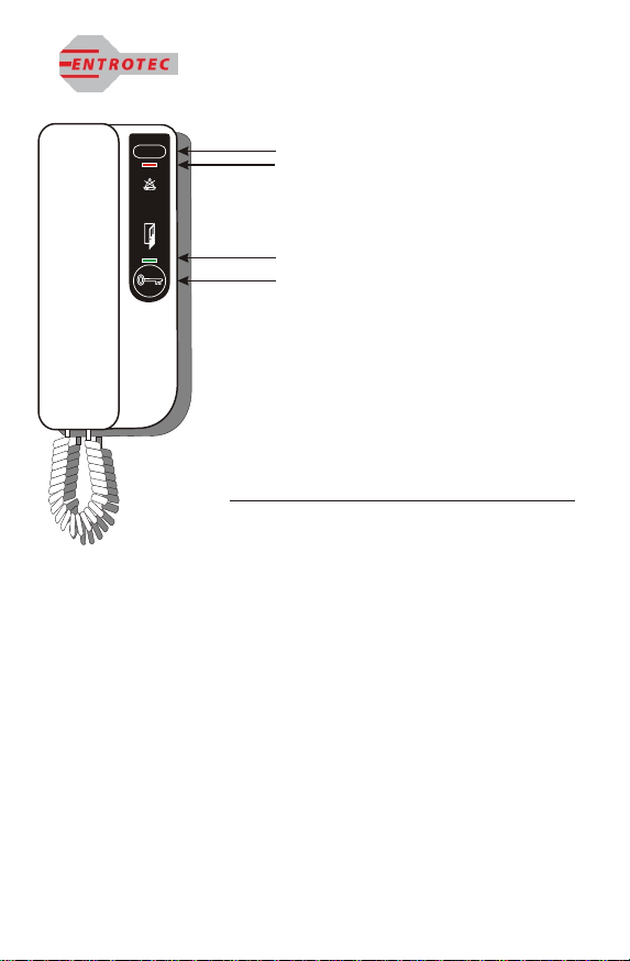
PRIVACY SWITCH
5). If you do not wish to be disturbed or annoyed by nuisance calls, press the
privacy switch (the LED will illuminate to remind you that the handset is
in privacy mode). When in this mode the call tone is muted until you reset
the switch by pressing it again.
Privacy Switch
Privacy on LED
Door Open LED
Lock Release Button
GENERAL NOTES
The door entry phone system
is designed so that you have a
limited time to answer a call
and allow the caller access or
not. This is to save inconvenience
to other users of the system.
ON
PRIVACY
ON PRIVACY
DOOR OPEN
ENTROTEC LTD.
RH3+ TELEPHONE-INSTRUCTIONS FOR USE
For AC/DC Buzzer Handsets
SW1 SW2
RD
WE
BK
YW
SW3
Tone
Buzz
LK10
ED
RH
SW4
Call Tone
Volume
Red
Black
Piezo
ENT0886 Rev 3
DR
VT
0V
BZ
S2
S1
DS
EX
CB
X
ALM
ED
RH
SW5
Anti
Lock
Non
LK6
NEG
DS
POS
NEG
DS
POS
PL3
PL5
LK7
ED
Tone Buzz
RH
D2
D3 Door Status LED (Green when door Open).
Privacy LED (Red when On Privacy).
Timer Links
LK1
LK2
LK3
PL2
ED4 Only Privacy
Switch
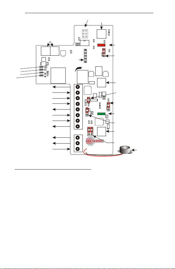
PIC Programming Link
ED4 Only.
Door Release Trigger
11-15V DC Input
0V Input
Call Tone or Buzz Input
Handset Microphone Output
Handset Speaker Input
Door Status Input
Amplified Call Tone Output
Call Back (SW4) Output
‘X’ Connection throughput
Alarm Input 11-15v DC
Call Back Or Aux Switch
Lock Release Switch
Adjusts
Call Tone
Volume
Cradle Switches
Call Tone Input Selection 1 (LK10).
Call Tone Input Selection 2 (LK7).
Lock Release Trigger Selection (LK6).
For AC/DC Buzzer systems select Non.
Door Status Input Select (PL3).
RH3+ Connection Details & Jumper Link Settings.
E rpiece
a
Erpiece 0v
a
Mic op n
r ho e
Mi p
cro hone 0v
Phone
Identifier
Label
Terminal Number/ID.
1). Door Release Trigger (DR). This output goes low when the Door Release switch SW5 is pressed. Note: This is a low going pulse of
a few milliseconds and provides an anti-lockdown circuit. To bypass this circuit and have a permanent trigger when the switch is
pressed move LK6 to ‘Non/RH’ position. For AC/DC Buzzer systems select the ‘Non’ mode.
Note: The handset must be lifted to use the Door Release Button.
2). DC Input (VT). The handset will function with a DC input range between 11-15v DC.
3). 0v Input (0v). The handset is designed to work on systems that use a common ground/0v supply for its reference point.
4). Call Tone or Buzz Input (BZ). The handset will accept various call inputs, a generated tone, 12v AC ring or a 12v DC ring. To use a
generated tone or 12v AC ring LK7 & LK10 jumpers (Call Tone Input Selection 1 & 2) should be set for ED/Tone input. To use 12v DC
ring (using internal piezo buzzer) set LK7 & LK10 to Buzz/RH position.
5). Handset microphone Output (S2). Speech output from handset to the speaker in the front panel.
6). Handset Speaker Input (S1). Speech input from the microphone in the front panel to the handset earpiece.
7). Door Status Input (DS). Input signal from the front door to advise that the door is open and illuminates DS (Green LED). This is
as standard a NO contact at the door when closed. A switched 0v input is set as standard with the jumper links at PL3 linked between
NEG/DS on both sides of PL3 (Switched 0v). A switched 12v input may be used, to do this move both Door Status Input Select Links to
the DS/POS position.
8). Amplified Call Tone Output (EX). The ‘EX’ connection is an amplified version of the call tone input on the ‘BZ’ terminal. It amplifies
the input from 2.5v-12v DC call tone to the voltage available at the handset (11-15v DC). It is imperative that this terminal is only used
to extension sounders, flashing beacons and other AUX equipment including additional handsets added.
9). Call Back (SW4) Output (CB). The ‘CB’ connection is for concierge systems and is used for calling the concierge. This output could
also be used to trigger additional door(s) via timer/relays or trigger other equipment. The output is NO going closed with switched 0V.
10). ‘X’ Connection Throughput (X). The ‘X’ connection is merely a connection point for ease of wiring. It has no connection to any circuitry
on the handset.
11). Alarm Input 11-15v DC (ALM). The ‘ALM’ input is used to sound the internal Piezo sounder when a 11-15v DC input is applied.
V.A.Turner Issue No.002 11/02/2011
Piezo Sounder
Notes: All Jumper Links Shown set to ED series
handset configurations (as standard).
See below for other settings in Terminal
Number/ID.
See note for Call Tone Isolation link ‘PL5’
Call tone DC Isolation Link (PL5).
Remove if isolation giving tone level
issues.
Privacy Switch
Privacy on LED
Door Open LED
Lock Release Button
GENERAL NOTES
The door entry phone system
is designed so that you have a
limited time to answer a call
and allow the caller access or
not. This is to save inconvenience
to other users of the system.
ON
PRIVACY
ON PRIVACY
DOOR OPEN
1) When called, the telephone will give a distinctive pulsing tone for up to 25
seconds and then stop. You have approx. 30 seconds to answer the call from
the start of the call tone. If the call is not answered within the call period, then
the system will reset to allow other visitors to make a call.
2) To answer the call remove the handset from the cradle and speak to the caller.
(You have approx. 2 minutes to speak to the caller and then the system will
reset).
3) To let the caller gain access, press the lock release button and this will open
the door for approximately 10 seconds.
4) When you have completed the call, replace the handset to reset the system.
PRIVACY SWITCH
5) If you do not wish to be disturbed or annoyed by nuisance calls, press the
privacy switch (the Red LED will illuminate to remind you that the handset is in
privacy mode). When in this mode the call tone is muted until you reset the
switch by pressing it again. If you wish to terminate the privacy period press the
privacy switch once and the Red LED will extinguish.
ENTROTEC LTD.
RH3+ TELEPHONE-INSTRUCTIONS FOR USE
For DC Call Tone Handsets

WHITE/BLUE
BLUE/WHITE
WHITE/ORANGE
ORANGE/WHITE
WHITE/GREEN
GREEN/WHITE
WHITE/BROWN
DR
VT
0V
BZ
S2
S1
DS
EX 8
DS 7
S1 6
S2 5
BZ 4
0V 3
VT 2
DR 1
CW1308
PREFERRED COLOUR CODING FOR WIRING HANDSETS.
RH3+ HANDSET CONNECTION DIAGRAM
WIR/SCH0111/
001/Rev1V
WIRING DIAGRAM
AND COLOUR
SCHEME FOR
RH3+ HANDSETS
2. Terminal 8 must only be connected to an Extension
Sounder, Flashing Beacon or other Aux. Equipment.
ENTROTEC LTD
Access House
5 Ashwood Court.
Oakbank
Livingston
EH53 0TL.
TEL.01506 886230
FAX.01506 886233
DATE:
DRAWN BY:
DRG.NO. DESC.
IMPORTANT.
ALL CABLES TO BE KEPT WELL AWAY FROM HIGH VOLTAGE CABLES.
PLEASE CONSULT OUR INSTALLATION GUIDELINE SHEET OR CONTACT
OUR TECHNICAL DEPT. FOR ADVICE ON 08448586370.
V.A.Turner
011/02/2011
Installer Please Note:
1. All RH3+ handsets are fitted with a Call Tone Volume
adjustment. This maybe adjusted to suit level required.
Factory setting is full volume.
Manufactured in the UK
CB 10
X 11
ALM 12
CB
X
Apex Systems Only From External Alarm
Output Trigger (12v on
alarm activation).
BROWN/WHITE
WHITE/GREY
1) When called up the telephone will give a distinctive buzzing tone.
2). To answer the call remove the handset from the cradle and speak to
the caller.
3). To let the caller gain access, simply push the lock release button and
keep it depressed for approximately 5 seconds to allow the visitor gain
access.
4). When you have completed this, replace the handset in it’s cradle.
PRIVACY SWITCH
5). If you do not wish to be disturbed or annoyed by nuisance calls, press the
privacy switch (the LED will illuminate to remind you that the handset is
in privacy mode). When in this mode the call tone is muted until you reset
the switch by pressing it again.
Privacy Switch
Privacy on LED
Door Open LED
Lock Release Button
GENERAL NOTES
The door entry phone system
is designed so that you have a
limited time to answer a call
and allow the caller access or
not. This is to save inconvenience
to other users of the system.
ON
PRIVACY
ON PRIVACY
DOOR OPEN
ENTROTEC LTD.
RH3+ TELEPHONE-INSTRUCTIONS FOR USE
For AC/DC Buzzer Handsets
Other manuals for RH3+
1
Table of contents
Other Entrotec Telephone manuals

Popular Telephone manuals by other brands


Telematrix
Telematrix Marquis 2802MWS Installation and user guide

Telematrix
Telematrix Marquis Series 3300LBY user guide

AEI COMMUNICATIONS
AEI COMMUNICATIONS SSP-9210-S Quick installation guide

AT&T
AT&T Four-Line Intercom Speakerphone 974 user manual

WatchNet
WatchNet AVCDP7 quick guide

GE
GE 18558 user guide