envea ProGap 2.0-BS Ex User manual

OPERATING INSTRUCTIONS
ProGap 2.0-BS (Ex)
LEVEL DETECTION WITH FILLING STREAM DETECTION
ENVEA - SWR engineering - Gutedelstraße 31 – 79418 Schliengen - GERMANY
Tel : +49 (0) 7635 827248-0 / info.swr@envea.global / www.swr-engineering.com

2
TABLE OF CONTENTS Page
1. System overview . . . . . . . . . . . . . . . . . . . . . . . . . . . . . . . . . . . . . . . . . . . . . 3
2. Function . . . . . . . . . . . . . . . . . . . . . . . . . . . . . . . . . . . . . . . . . . . . . . . . . 3
3. Safety . . . . . . . . . . . . . . . . . . . . . . . . . . . . . . . . . . . . . . . . . . . . . . . . . . . .4
3.1 Normal use . . . . . . . . . . . . . . . . . . . . . . . . . . . . . . . . . . . . . . . . . . . . . . .4
3.2 Identification of hazards . . . . . . . . . . . . . . . . . . . . . . . . . . . . . . . . . . . . . . . .4
3.3 Operational safety . . . . . . . . . . . . . . . . . . . . . . . . . . . . . . . . . . . . . . . . . . .4
3.4 Technical statement . . . . . . . . . . . . . . . . . . . . . . . . . . . . . . . . . . . . . . . . . .4
4. Mounting and installation . . . . . . . . . . . . . . . . . . . . . . . . . . . . . . . . . . . . . . . . 5
4.1 Typical components of a measurement point . . . . . . . . . . . . . . . . . . . . . . . . . . . .5
4.2 Required equipment . . . . . . . . . . . . . . . . . . . . . . . . . . . . . . . . . . . . . . . . . .5
4.3 Sensor installation . . . . . . . . . . . . . . . . . . . . . . . . . . . . . . . . . . . . . . . . . . .5
4.4 Mounting of the Evaluation unit. . . . . . . . . . . . . . . . . . . . . . . . . . . . . . . . . . . .6
5. Use in hazardous areas . . . . . . . . . . . . . . . . . . . . . . . . . . . . . . . . . . . . . . . . . 7
6. Electrical connection . . . . . . . . . . . . . . . . . . . . . . . . . . . . . . . . . . . . . . . . . . 8
6.1 Electrical connection of sender . . . . . . . . . . . . . . . . . . . . . . . . . . . . . . . . . . . .8
6.2 Electrical connection of receiver . . . . . . . . . . . . . . . . . . . . . . . . . . . . . . . . . . .8
6.3 Electrical connection of Evaluation unit . . . . . . . . . . . . . . . . . . . . . . . . . . . . . . .8
7. Commissioning. . . . . . . . . . . . . . . . . . . . . . . . . . . . . . . . . . . . . . . . . . . . . . 9
7.1 Basic settings . . . . . . . . . . . . . . . . . . . . . . . . . . . . . . . . . . . . . . . . . . . . .9
7.2 Menu description . . . . . . . . . . . . . . . . . . . . . . . . . . . . . . . . . . . . . . . . . . .9
7.3 Menu structure. . . . . . . . . . . . . . . . . . . . . . . . . . . . . . . . . . . . . . . . . . . .10
7.4 Start-up procedure . . . . . . . . . . . . . . . . . . . . . . . . . . . . . . . . . . . . . . . . . 11
8. Error signalling . . . . . . . . . . . . . . . . . . . . . . . . . . . . . . . . . . . . . . . . . . . . . .11
9. Notes . . . . . . . . . . . . . . . . . . . . . . . . . . . . . . . . . . . . . . . . . . . . . . . . . . .12
10. Default settings . . . . . . . . . . . . . . . . . . . . . . . . . . . . . . . . . . . . . . . . . . . . . 12
11. Impuls output . . . . . . . . . . . . . . . . . . . . . . . . . . . . . . . . . . . . . . . . . . . . . . 13
12. Technical data . . . . . . . . . . . . . . . . . . . . . . . . . . . . . . . . . . . . . . . . . . . . . . 14
3
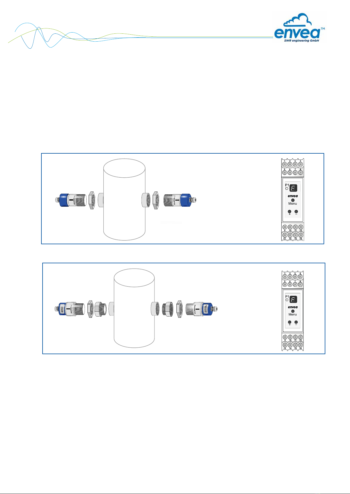
1. System overview
A measuring point consists of the following components:
•G-1½” welded bracket for assembly of the units
•2 x lock nut for locking the sender and receiver unit
•Process adapter (optional)
•Sender unit
•Receiver unit
•Evaluation unit
2. Function
The microwave barrier is a contact-free measuring method and can be used on both metallic and non-
metallic pipes, tanks, shafts, chutes, bellows etc. As non-conductive materials such as plastics are able to
penetrate, it can be used for detection from outside or through a window. In this way, the measurement can
be fully decoupled from the process – to measure aggressive, abrasive or coarse materials for instance.
In very difficult conditions – i.e. temperatures up to 200 °C, pressure to 20 bar as well as all dust Ex zones –
the ProGap 2.0-BS can be used with the aid of a process adapter. The filling stream detection can only be
guaranteed for metallically shielded tanks.
Fig. 1: Overview of measuring point: ProGap 2.0-BS
+
Fig. 2: Overview of measuring point: ProGap 2.0-BS Ex
+
4
3. Safety
The ProGap 2.0-BS dust sensor has a state-of-the-art, reliable design and has been tested and found to be in
a perfectly safe condition when it left the factory. Nevertheless, the system components may present dangers
to personnel and items if they are not operated correctly.
Therefore, the operating manual must be read in full and the safety instructions followed to the letter. If the device
is not used correctly for its intended purpose the manufacturer's liability and warranty will become void.
3.1 Normal use
•Only genuine spare parts and accessories from ENVEA - SWR engineering may be used.
3.2 Identification of hazards
•The operating manual refers to possible dangers when using the microwave barrier.
Warning!
•This symbol is used in the operating manual to denote actions which, if not performed correctly may
result in death or injury.
Attention!
•This symbol is used in the operating manual to denote actions which may result in danger to property.
3.3 Operational safety
•The microwave barrier may only be installed by trained, authorised personnel.
•During all maintenance, cleaning and inspection work on pipes or ProGap 2.0-BS components, make
sure that the system is in an unpressurised state.
•Switch off the power supply before performing any maintenance work, cleaning work or inspections on
pipes.
•The microwave barrier must be removed before welding work.
•The components and electrical connections must be inspected for damage at regular intervals. If any
signs of damage are found, this damage must be rectified before the devices are used again.
3.4 Technical statement
•The manufacturer reserves the right to adjust technical data concerning technical developments without
notice. ENVEA - SWR engineering will be delighted to provide information about the current version of
the operating manual, and any amendments made.
5
4. Mounting and installation
4.1 Typical components of a measurement point:
•G-1½” welded bracket for assembly of the units
•2 x lock nut for locking the units
•Process adapter (optional)
•Sender unit
•Receiver unit
•Evaluation unit
4.2 Required equipment
•Tested tools for the electrical connection
•60-mm open-ended spanner for lock nut
•Teflon tape for ensuring leak tightness
4.3 Sensor installation
Proceed as follows to install the sensor:
•Determine a installation site as free from vibrations as possible.
•We recommend a distance of 15 cm from adjacent walls.
•Weld on the sensor socket so that the faces of the sender and receiver are opposite each other on
the same level.
•It must be strictly ensured that the sensor socket is free of dirt and deposits.
•If the measuring point is not installed directly, the sensor socket can be closed with a cover
with G-1½” thread.
•It must be strictly ensured that the sender and receiver have the same orientation and are aligned
precisely to one another. (Polarisation label)
•Exceptional case: For distances up to 400 mm, the transmitter should be rotated 90° to attenuate the
signal.
•Once aligned, the sender and receiver unit must be locked with the lock nut.
•A maximum spacing between the sender and receiver of 25 m must not be exceeded.
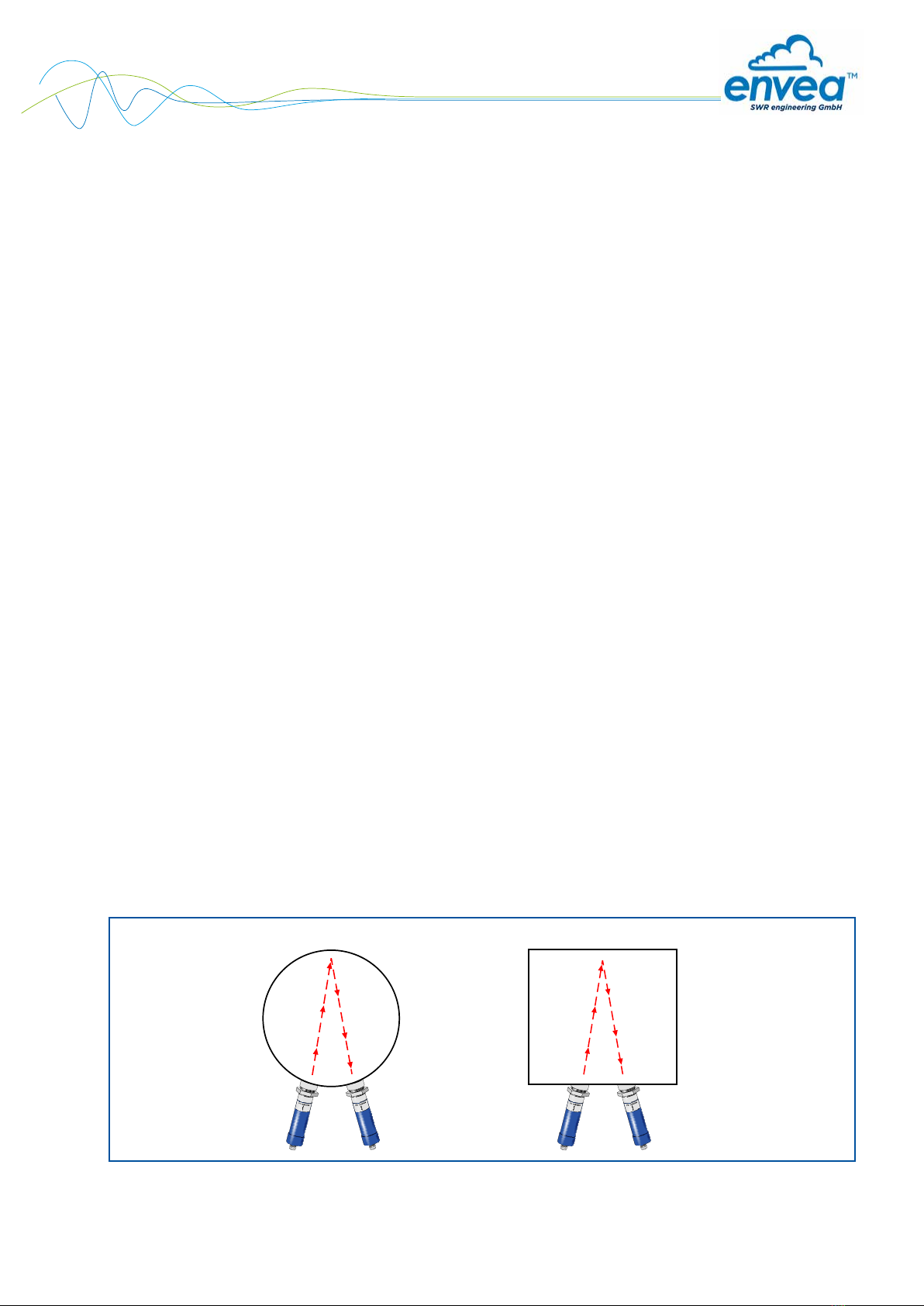
•If the sender and receiver cannot be installed opposite, installation on one side is possible (Fig. 3).
•If the material to be measured has a low bulk density or a low DK value, the sender and receiver can be
mounted on one side of the line (Fig. 3).
Fig. 3: Installation of the measuring point on one side
Round tank (metallic) Square tank (metallic)
6
4.4 Mounting of the Evaluation unit
The evaluation unit can be installed at a maximum distance of 300 m from the sender and receiver unit.
The cable should be two-core, twisted and shielded. A minimum cross section of 0.75 mm2should be
maintained. For distances longer than 100 m, the cross-section should be adjusted to 1.5 mm2.
118
35
90
90
23
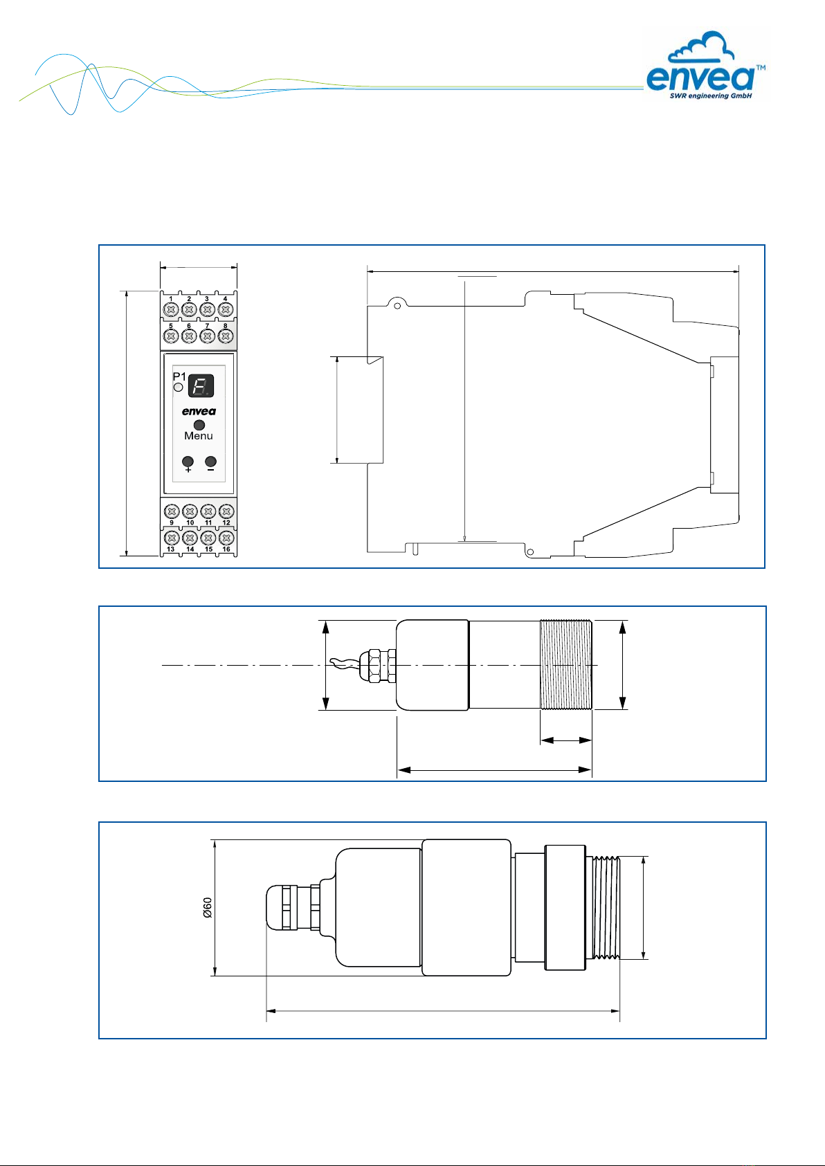
Fig. 4: Dimensions of evaluation unit in DIN Rail housing
Fig. 5: Dimensions of sender and receiver unit: ProGap 2.0-BS
103
ø 52
30
G 1 1/2"
155
G1 ½"
Fig. 6: Dimensions of sender and receiver unit: ProGap 2.0-BS Ex
G 1 1/2”
Ø 52

7
22 20 22
Non-explosive area
only with process
adapter
only with process
adapter
▼
▼
Explosive area
Dust Ex zone
Marking DustEx: II 3D Ex tc IIIC T85 °C Dc
5. Use in hazardous areas
Power supply
(observe type plate)
Voltage range
Power supply
24 V DC supplied by evaluation unit
Max. power consumption
1.5 W
Category II 3D Sensor in Zone 22
Housing protection class Sensor = IP65 / evaluation unit = IP40
Safety information for installation in explosive areas
1. Observe installation and safety instructions.
2. Install according to manufacturer’s instructions and applicable standards.
3. Do not operate the device outside the electrical and thermal parameters.
4. Mount the housing cover and cable entries properly to ensure the housing protection class.
5. Use cable glands and cable entries that are suitable for Category II 3D.
6. A process adapter must be used for installation of the ProGap 2.0-BS in an Ex zone.
Thermal data Category 3 (Zone 22)
Maximum permissible ambient temperature - 20 °C . . . + 60°C
Maximum surface temperature, sensor,
at +60 °C ambient temperature
+ 80 °C
Maximum process temperature, at +60 °C ambient
temperature, when using a Tecapeek process adapter
+ 220 °C
Maximum process temperature, at +60 °C ambient
temperature, when using a POM process adapter
+ 80 °C
8
6. Electrical connection
The evaluation unit can be installed at a maximum distance of 300 m from the sender and receiver unit. We
recommend an insulated, shielded cable with a minimum cross-section of 0.75 mm². From a cable length of
100 m, the cable cross-section must be enlarged to 1.5 mm². The sender/receiver system has an EMC screw
connection. This serves for mounting a cable shield. The shield should only be mounted on the sensor side.
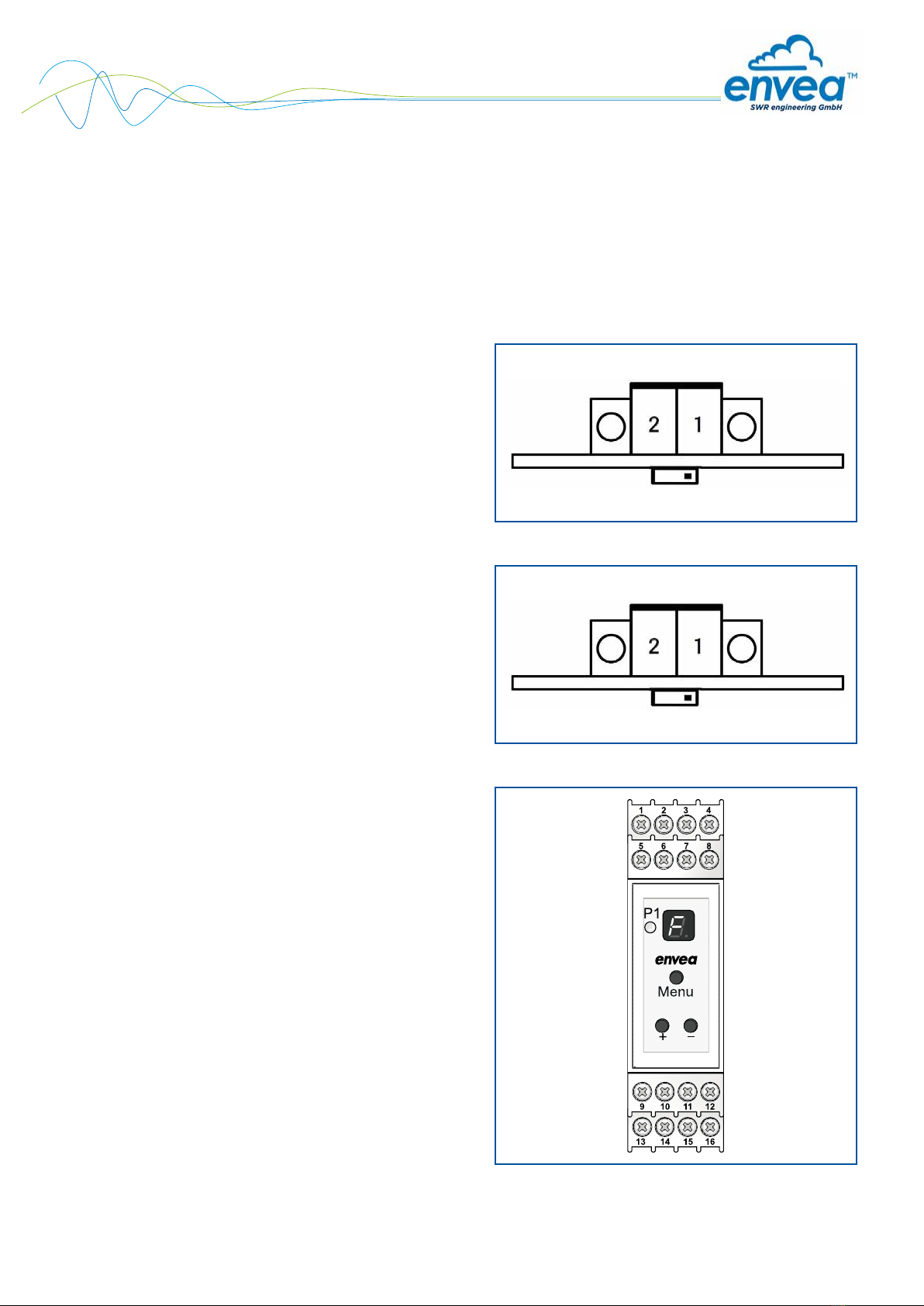
Fig. 7: Electrical connection of sender
6.1 Electrical connection of sender
1 Power supply 0 V
2 Power supply +24 V
S1 Dip switch for setting the material flow
monitoring (Hi/ Lo)
Fig. 8: Electrical connection of receiver
6.2 Electrical connection of receiver
1 Power supply 0 V
2 Power supply +24 V
S1 Dip switch for setting the level monitoring
(Hi/ Lo)
Fig. 9: Electrical connection of evaluation unit
6.3 Electrical connection of Evaluation unit
1 NA
2 NA
3 Power supply +24 V
4 Power supply 0 V
5 Open collector +
6 Open collector -
7 NA
8 NA
9 Sender cable 1 (0 V)
10 Sender cable 2 (+24 V)
11 Receiver cable 1 (0 V)
12 Receiver cable 2 (+24 V)
13 NA
14 Relay contact NC
15 Relay contact COM
16 Relay contact NO
Hi Lo
Hi Lo

9
7. Commissioning
7.1 Basic settings
Make sure that the transmitter and receiver are installed opposite each other. At distances up to 400 mm,
the transmitter should be rotated 90° to attenuate the signal. In addition, a dip-switch is installed in the
transmitter via which the sensitivity of the material flow detection can be set. If the dip switch is set to “High”,
even small movements of material will be detected. For a distance up to 400 mm it is recommended to select
the setting “Low”.
The receiver has the additional option of setting of the level monitoring via a dip-switch. If “High” is selected,
larger distances can be monitored, with a distance of up to 400 mm, “Low” should be selected.
For better distinction, an “S” is printed on the transmitter board and the dip switch is red. An “E” is printed on
the receiver board and the dip switch is white.
If the sensors are installed correctly, commissioning can be started via the 7-segment display on the
evaluation unit.
7.2 Menu description
The 7-segment display is deactivated in normal operation. Only the decimal point LED (DP) flashes
continuously. If the Menu button is pressed for longer than 5 seconds, the Parameter Settings menu is
activated. If the Parameter Settings menu is activated, the menu items are shown on the 7-segment display
with numerals 1-9. After activating the menu, the Menu button can be used to toggle between the individual
menu items. The + and – buttons are used to change parameters in the selected menu. Depending on
the menu item, the response by the decimal point LED (DP-LED) will change. Menu item 9 is used to quit
and save the parameter changes. The changed parameters are saved with the + button; all changes are
discarded with the – button. In both cases, the menu is quit by pressing the button. If no entry is made for
longer than five minutes, changed parameters will be discarded and the Parameter Settings menu closed.

10
7.3 Menu structure
Menu point Function
1
Sensitivity of motion detection
DP LED lights up: High sensitivity
Even small movements are detected
DP LED does not light up: Low sensitivity
Small movements are ignored
Status LED P1 lights up: Motion was detected
2
Switching threshold of motion detection (resolution: 20 levels)
DP LED flashes slowly: Reduced switching threshold
Even small movements are detected
DP LED flashes rapidly: Increased switching threshold
Small movements are ignored
Status LED P1 lights up: Motion detection is detected
3
Sensitivity of level detection
DP LED lights up: High sensitivity
High signal strength for higher distance
DP LED does not light up: Low sensitivity
Low signal strength for smaller distance
Status LED P1 lights up: No material is detected
4
Switching threshold of level detection (resolution: 20 levels)
DP LED flashes slowly: Reduced switching threshold
A high signal attenuation is required for alarm output
DP LED flashes rapidly: Increased switching threshold
Even low signal attenuation leads to alarm output
Status LED P1 lights up: No material was detected
5
Switching delay of relay and open collector (resolution: 20 levels)
DP LED flashes slowly: Low delay (minimum: 0.5 sec)
DP LED flashes rapidly: High delay (maximum: 10 sec)
Status LED P1: Flashes in relation to the response delay; the switch on and
off time of the LED corresponds to the actual delay time
6
Switching response of relay
DP LED lights up: Relay switches if material with motion is detected (filling process)
DP LED does not light up: Relay switches as soon as material motion is detected (flow / no flow)
DP LED flashes rapidly: Relay switches if material without motion is detected (filling level)
DP LED flashes slowly: Relay switches if sender and receiver detect
Status LED P1 lights up: Selected option is fulfilled
7
Switching response by open collector (OC)
DP LED lights up: OC switches if no error is detected
DP LED does not light up: OC switches as soon as material motion is detected (flow / no flow)
DP LED flashes rapidly: OC switches if material without motion is detected (filling level)
DP LED flashes slowly: OC switches if sender and receiver detect
Status LED P1 lights up: Selected option is fulfilled
8
Switching response of status LED
DP LED lights up: Status LED P1 indicates the status of the relay contact
DP LED does not light up: Status LED P1 indicates the status of the open collector
Status LED P1: Indicates the current status
If the open collector is used for error analysis, the status LED P1 always indicates the state of the
relay contact.
9
Quit Settings menu
With + button: Quit menu and save parameter changes
With - button: Quit menu and discard parameter changes

11
7.4 Start-up procedure
The following points should be checked before the initial start-up:
•Correct installation of the measuring point
•Correct alignment of the polarisation
•Correct connection between the sensors and evaluation unit
•Heat-up time of at least five minutes
The parameters are set via the 7-segment display for optimal measuring value output. It must first be ensured
that the receiver detects the signal from the sender. For this, the beam path between the units must be free
and menu items 3 + 4 set so that LED P1 lights up (no material detection).
Once it is ensured that the sender and receiver are detecting, the settings for the motion detection can
be made in menu 1 + 2. The motion detection is performed during the process and must be set so that
the current material is detected in the process (LED P1 lights up). After the motion detection is set, we
recommend checking again whether the receiver detects the signal from the sender during the process
(Menu 3+4, LED P1 lights up).
The microwave barrier must then be interrupted completely with the material to be measured. Once the
beam path is interrupted, it is necessary to check at menu items 3 + 4 that LED P1 has switched off (material
detection).
Once the process parameters are set, the switch-off delay of the relay and open collector output can be set at
menu item 5. In menu items 6 + 7, it is then necessary to select the desired switching response for the relay
and open collector output. For a better overview, the status LED P1 can be assigned to the state of the relay
contact or the open collector at menu item 8.
The open collector output must be supplied actively with a voltage (max. 30 V, 20 mA).
Once all parameters are set properly, these must be saved by pressing the + button at menu item 9.
The initial start-up is now completed, allowing the ProGap 2.0-BS to alarm reliably as soon as
the selected limit level is reached.
8. Error signalling
Error Cause Action
Relay contact does not switch
when filling level is reached
Low bulk density of material
Set microwave barrier for
sensitivity
Set motion detection as
insensitive
Check installation situation,
change if necessary
Low DK value of material
Sender and receiver do not see
each other
Polarisation distorted
Display of an “S” on the
7-segment display Sender unit was not detected
Check electrical connection;
Contact ENVEA -
SWR engineering
Display of an “E” on the
7-segment display Receiver unit was not detected
Check electrical connection;
Contact ENVEA -
SWR engineering
Display of a “P” on the
7-segment display Parameter saving failed Perform start-up again and save
parameters again
If several errors are active, these are shown sequentially on the 7-segment display.
12
9. Notes
•If a sensor error is detected (disconnected sensor or sender/receiver mixed up), the evaluation unit will
then report “Level detected”.
•In case of a parameter error, basic settings are used and the device continues working.
•A minimum distance of 15 cm to the wall is recommended in order avoid disturbing reflections.
•In case of restricted space or material with low bulk density or low DK value, installation on one side of
the vessel is possible.
•Various process parameters are available to protect the sensor, comply with ATEX zones or resolve
difficult process conditions.
•If the material is not detected, even with an installation on the same side, a special attenuation foil can be
obtained from ENVEA - SWR engineering.
Process adapters are essential to use this foil.
•In case of distances below 400 mm, we recommend rotating the sender or receiver by 90°.
•The pipe where the measuring point is installed must be earthed.
10. Default settings
If the + and – buttons are pressed simultaneously for longer than 10 s, all parameters are reset to the default
setting. If the parameters are still at the default setting “d” will flash in the display.
Menu point Parameter Default Range Description
1
Sensitivity of motion
detection
1 0 -1 High sensitivity
2Switching threshold
of motion detection 10 0 - 20 Medium threshold
3Sensitivity of level
detection 1 0 - 1 High sensitivity
4Switching threshold
of level detection 10 0 - 20 Medium threshold
5 Switching delay 1 0 - 20 Switching delay = 0.5 sec
6Function of relay
contact 1 0 - 3 Relay contact switches as soon as the
sender and receiver detect
7Function of open
collector 0 0 - 3 Open collector switches upon motion
detection
8 Function of LED P1 1 0 - 1 Status LED P1 indicates the status of
the relay output
13
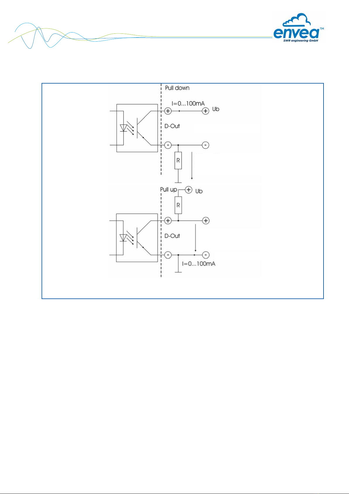
Open: 0 V
Closed: Ub - 0.7 VClosed: Ub - 0.7 V
Open: Ub
Closed: 0.7 VClosed: 0.7 V
Open Collector
Open Collector
11. Impuls output
R = (Ub - 0.7 V)/l

14
EN 06/04/2020
12. Technical data
Sensor
Material Housing: Stainless steel 1.4571 - sensor insulation: POM
Protection type IP65
Using in EX-Zones Outside: Cat. 3D
Inside: Cat. 1/3D (with process-adapter)
Process temperature - 20 ... + 80 °C
- 20 ... + 220 °C (with process adapter)
- 20 ... + 1000 °C (with ceramic flange)
Ambient temperature - 20 ... + 60°C
Operating pressure Max. 1 bar
Max. 20 bar (with process adapter)
Detection range 0.1 ... 25 m
Voltage supply 24 V DC supplied by evaluation unit
Power consumption Max. 20 VA
Current consumption Max. 850 mA
Operating frequency K band 24.125 GHz / ± 100 MHz
Transmission power Max. 5 mW
Dimensions of ProGap 2.0-BS Housing: L 103 mm / Ø 52 mm / thread: L 30 mm / Ø G 1½
Dimensions of ProGap 2.0-BS Ex Housing: L 155 mm / Ø 60 mm / thread: L 30 mm / Ø G 1½
Cable gland M16 (Ø 5-10 mm)
Weight of ProGap 2.0-BS Approx. 560 g
Weight of ProGap 2.0-BS Ex Approx. 880 g
Evaluation unit
Supply voltage 24 V DC ± 10 %
Power consumption 3.5 W
Current consumption 120 mA at 24 V
Relay contact
Max. switching power: 250 V AC
Max. inrush current: 6 A
Max. switching power 230 V AC: 250 VA
Max. switching current DC1: 3/110/220 V: 3/0.35/0.2 A
Min. switching load: 500 mW (10 V/5 mA)
Weight Approx. 172 g
Ambient operating temperature - 10 ... + 45°C
Dimensions 23 x 90 x 118 mm (W x H x D)
DIN rail fastening DIN 60715 TH35
Connection terminals cable cross-section 0.2 - 2.5 mm2[AWG 24-14]
Pulse output Open collector – max. 30 V, 20 mA
Protection type IP40
All rights reserved.
SWR engineering Messtechnik GmbH
Gutedelstraße 31 · 79418 Schliengen (Germany)
Fon +49 7635 827248-0· Fax +49 7635 827248-48 · www.swr-engineering.com
PART OF THE ENVEA GROUP
This manual suits for next models
1
Table of contents


