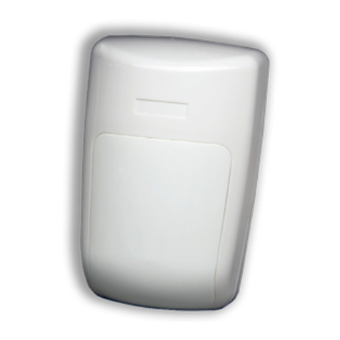
ENVIO Luna CACT-DSC-500ST User manual

Luna Series | CACT-DSC-500ST
www.enviosecurity.com
CACT-DSC-500ST
5MP DSC PIR DETECTOR WITH AUDIO
Technical Specification Camera
Image Sensor
1/2.9”SONY STARVIS CMOS
Effective Pixels
2592(H)×1944(V),5MP
Scanning System
Progressive
Minimum Illumination
0.001Lux/F1.6, 30IRE
Lens Type
Fixed Lens
Focal Length
3.7mm
Angle of View
82°
Resolution
2592x1944
Video Output
1-channel BNC high definition video output
AHD/HD-TVI 5MP@20FPS;HD-CVI 4MP@25FPS
OSD Menu
Multi-language
BLC Mode
BLC / HLC / DWDR
WDR
WDR
Gain Control
AGC
Noise Reduction
3D
White Balance
Auto/Manual
Audio
Build in Microphone
Power Supply
12V DC ±30%
Power Consumption
Max 3W (12V DC
Technical Specification Pir Detector
Detection method
Voltage
Temperature compensation
Alarm Duration
Quad Pyroelectric Sensor (four elements)
8.2 to 16 Vdc
Monochrome: 115 mA Color: 150 mA Yes
Alarm output
2 ±1 s
Tamper
N.C 28 Vdc 0.1 A with 10 Ohm series resistor
open when cover is removed
Stabilization Time
1 min
LED light
RFI immunity
Red LED on during alarm
More than
10 V/m, 80% AM from 80 MHz to 1GHz
Electrostatic Immunity
8 kV contact, 15 kV air
Immunity to Pulses
Operating temperature
Dimensions
2,4 kV @ 1,2 joules
-
10 ºC a +50 ºC
116mm x 62,5mm x 40mm
•1/2.9” Sony Starvis sensor
•5mp (2592x1944
•3.7mm Fixed Lens
•Audio Out with Build in Microphone
•4in1 AHD,HD-CVI,HD-TVI,CVBS (UTC)
•IP20
•DC12V
•Pets Immunity
•15mt Detection Area
Analog High Definition PIR Detector
1 WARNING & PRECAUTIONS
Dear Customer, we thank you for choosing one of our products whose correct use
guarantees solutions of the highest quality and reliability over time. This manual
provides instructions for using the product.
2 CONNECTION
Make sure the camera is not powered before making connections.
The video cable is connected to the female bayonet BNC connector, which is then
taken to the monitor or DVR in general via RG59 type coaxial cable and BNC
connector. Twisted pair cables can also be used with balun converters.
Check that the power supply is correct and provided for the camera model used.
The use of adequate power supply units is recommended. 12Vdc / 1A or 12Vdc /
1,5A stabilized is recommended. The pin required is the standard 5.5 mm. Beware
of power extension cables that are too long or have a small section, which could
introduce an excessive voltage drop, especially when the IR illuminator is turned on.
The values expressed in the following table are to be considered at a temperature
of 20 ° C [68 ° F].
3 TYPICAL INSTALLATION
Choice of location for mounting. Select the most suitable location to detect the
presence of an intruder. (Corner installation is recommended). See coverage area
(Fig. 3).
The highly sensitive four-element sensor
detects the movements that cross the
beams; it is slightly less sensitive at
detecting movement towards the
detector. Avoid the following locations:
Exposure to sunlight. Facing areas that
can change temperature rapidly. *
Locations with air ducts or strong air
currents. The detector performance is
optimal in a uniform and stable
environment.
The detector must be installed and used
in environments with a pollution degree
not exceeding factor 2 and overvoltage
category II, IN NON-HAZARDOUS
ENVIRONMENTS, indoors only. The
detector is designed to be installed by
qualified personnel only

Luna Series | CACT-DSC-500ST
www.enviosecurity.com
CACT-DSC-500ST
5MP DSC PIR DETECTOR WITH AUDIO
4 FIXING THE DETECTOR BASE
1. To remove the lid, undo the locking screw and gently lift the lid. Fig. 2-12
2. To remove the circuit board, carefully unscrew the board locking screw. Fig. 2-7
3. Thread the cable through the bracket and holes "A". Fig.1
4. Fix the detector base to the wall or ceiling using the suitable joint. Fig.
5. Use the supplied fixing devices: screws and plugs to fix the detector to the wall *
6. Reinstall the PCB and tighten the locking screw securely. Make the connections on the terminal block.
7. Connect the camera cable to the PCB connector.
8. Replace the lid by inserting it into the appropriate closing hooks and tighten the locking screw.
Fig.1 – Mounting holes
Fig.2 – Detector installation
wall mounting
ceiling mounting
5
DETECTOR INSTALLATION
Description of the terminal block (See fig. 5)
Terminals1&2-marked"T2,T1"(SABOTAGE). Ifthetamperfunctionisrequired,connecttheseterminalstoa
normally closed 24-hour zone of the control panel. If the
cover of the detector is opened, an alarm signal will be sent
immediately to the control panel.
Terminals 3 & 4 - marked "AUDIO: OUT, GND" Audio signal output. These two terminals must be connected to an
audioinput.Terminals4&5-marked"VIDEO:GND,OUT"
Videosignaloutput.Thesetwoterminalsmustbe
connected to a video input. Terminals 6,7 & 8 - marked “RELAY: NO, COM & NC” Detector output relay contacts.
Connect to a normally closed or normally open zone of the control panel.
Terminal 9 - marked “-” (ground) Connect to the negative or ground of the control unit
Terminal 10 - marked “+” (+12V) Connect to the positive of a 8.2 to 16 Vdc power source (typically supplied by the
burglar-alarm control unit).
Fig. 5 – terminal board
1. Depending on the camera models. This model has a coaxial control:
2. Access the DVR menu in the appropriate coaxial configuration section (in ENVIO DVRs this setting is called "XVI control".
3. Press the central console button that appears on the monitor to enter the menu home page.
4. Select topic / function of interest using the scroll up / down buttons.
5. Use the left or right buttons to select the different operating modes.
6. Move to [EXIT] and press the center button to exit the setting mode, without saving the settings.
7. Navigate to [SAVE & EXIT] and press the center button to exit the setting mode, saving the settings
Popular Security Sensor manuals by other brands
Takex
Takex MS-100E instruction manual
GE Security
GE Security EST3 Installation and service manual
cias
cias PYTHAGORAS2 Series installation manual
Surefire
Surefire iBURNER BMS-100 Installation & operation manual

Videofied
Videofied OMV-VX Install Sheet
System Sensor
System Sensor 2300TB Installation and maintenance instructions
