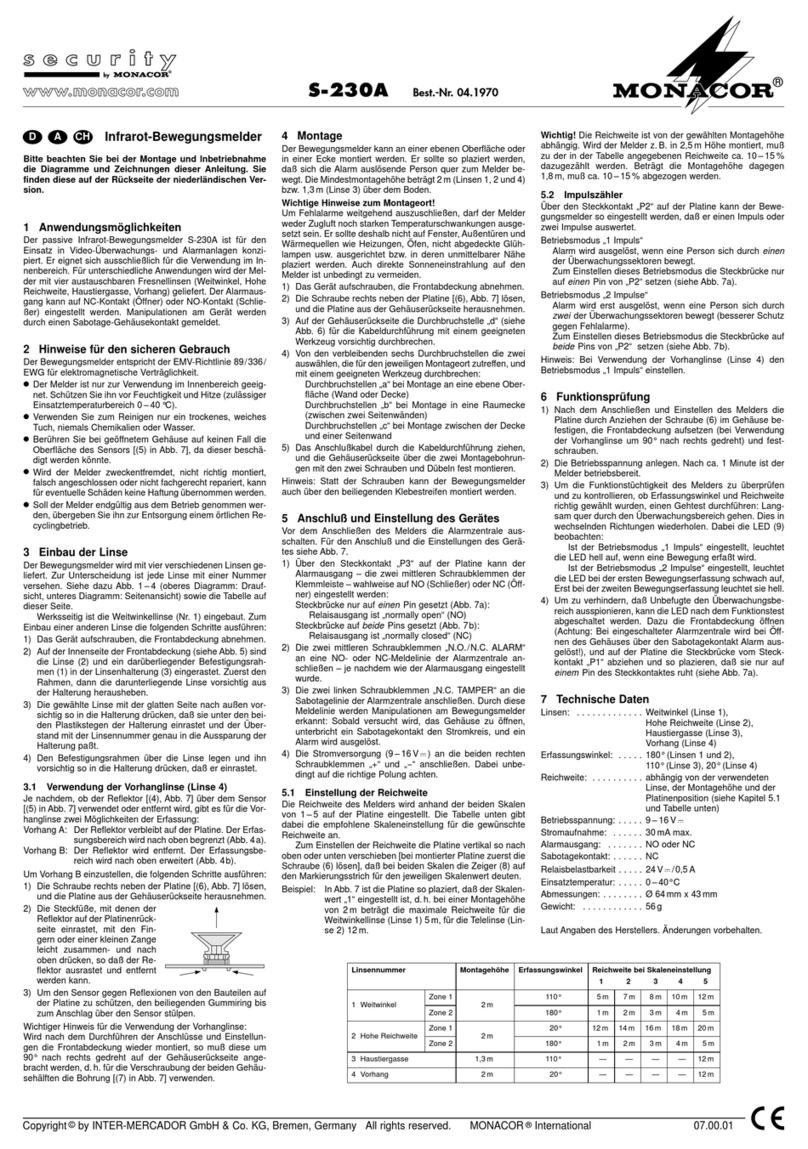
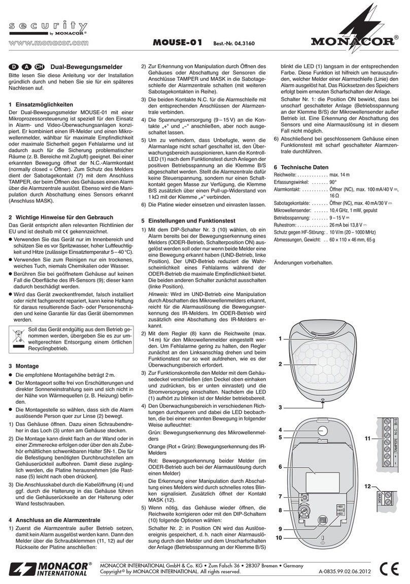
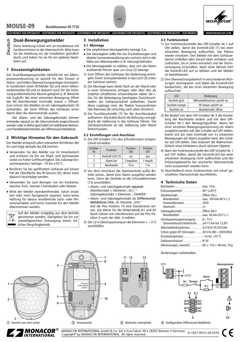
Monacor PIR-990 User manual

PIR-990 Best.-Nr. 04.0060
Copyright©by MONACOR INTERNATIONAL GmbH & Co. KG, Bremen, Germany. A rights reserved. A-0851.99.01.05.2008
D A CH
®
®
PIR-Bewegungsmel er
Bitte lesen Sie diese Anleitung vor der Installation
gründlich durch und heben Sie sie für ein späteres
Nachlesen auf.
1 Einsatzmöglichkeiten
Der Bewegungsmelder PIR-990 (passiv infrarot) ist
speziell fur den Einsatz in Alarm- und Video-Über-
wachungsanlagen konzipiert. Bei einer erkannten
Bewegung öffnet oder schließt der Alarmkontakt
(wählbar). Ein integrierter 3,9-kΩ-Widerstand kann für
den Abschluss einer Melderlinie genutzt werden. Die
Empfindlichkeit lässt sich so einstellen, dass vorbei-
laufende Haustiere keinen Alarm auslösen. Zum
Schutz des Melders dient der Sabotagekontakt (7),
der das Öffnen des Gehäuses an die Alarmzentrale
übermittelt.
2 Wichtige Hinweise für en Gebrauch
Das Gerät entspricht allen erforderlichen Richtlinien
der EU und ist deshalb mit gekennzeichnet.
GVerwenden Sie das Gerät nur im Innenbereich und
schutzen Sie es vor Spritzwasser, hoher Luftfeuch-
tigkeit und Hitze (zulässige Einsatztemperatur
-
10 °C bis +50 °C).
GVerwenden Sie zum Reinigen nur ein trockenes,
weiches Tuch, niemals Chemikalien oder Wasser.
GBeruhren Sie bei geöffnetem Gehäuse auf keinen
Fall die Oberfläche des IR-Sensors (8); dieser kann
dadurch beschädigt werden.
GWird das Gerät zweckentfremdet, falsch installiert
oder nicht fachgerecht repariert, kann keine Haftung
fur daraus resultierende Sach- oder Personenschä-
den und keine Garantie fur das Gerät ubernommen
werden.
3 Montage
GDie Montagehöhe sollte zwischen 2 m und 3 m lie-
gen.
GDer Montageort sollte frei von Erschütterungen, di-
rekter Sonneneinstrahlung und Zugluft sein und
sich nicht in der Nähe von Wärmequellen (z. B. Hei-
zung) befinden.
GDie Montagestelle so wählen, dass sich die Alarm
auslösende Person quer zur Linse (2) bewegt.
1) Die Schraube (3) entfernen und das Gehäuse
öffnen.
2) Die Montage kann direkt flach an der Wand oder in
einer Zimmerecke erfolgen oder über den als Zube-
hör erhältlichen, schwenkbaren Halter BR-990. Für
die Befestigung am Halter BR-990 die beiden
Löcher (4) nutzen. Andere für die Befestigung und
die Kabeldurchführung benötigten Durchbruchstel-
len am Gehäuserückteil aufbohren. Wenn nötig, die
Rastnase (9) leicht nach rechts drücken und die
Platine herausnehmen, damit die Durchbruchstel-
len zugänglich werden.
3) Die Anschlusskabel durch die gewählte Kabelöff-
nung und ggf. durch die Halterung in das Gehäuse
fuhren und die Gehäuseruckseite an der Halterung
oder Wand festschrauben.
4) Die Platine ggf. wieder einsetzen und einrasten las-
sen.
5) Wenn die Halterung verwendet wird, diese an der
Wand oder Decke festschrauben und den Bewe-
gungsmelder auf den Überwachungsbereich aus-
richten.
Soll das Gerät endgültig aus dem Betrieb ge-
nommen werden, übergeben Sie es zur um-
weltgerechten Entsorgung einem örtlichen
Recyclingbetrieb.
4 Anschluss an ie Alarmzentrale
Zuerst die Alarmzentrale außer Betrieb setzen, damit
kein Alarm ausgelöst werden kann. Dann den Melder
uber die Schraubklemmen (6) anschließen:
1) Die beiden Klemmen TAMPER in die Sabotage-
schleife der Alarmzentrale schalten (mit weiteren
Sabotagekontakten in Reihe).
2) Die Klemmen COM und NC fur die Alarmschleife
mit den entsprechenden Anschlussen der Alarm-
zentrale verbinden. Beim letzten Melder einer Mel-
derlinie kann statt eines externen Abschlusswider-
stands der interne 3,9-kΩ-Widerstand genutzt
werden (vgl. Daten der Alarmzentrale). In diesem
Fall stattdessen die Klemmen COM und 3.9k
anschließen.
Ein Abschlusswiderstand definiert den Ruhe-
strom zur Überwachung der Leitung. Bei einer Ab-
weichung kann die Alarmzentrale einen Alarm aus-
lösen.
3) Die Spannungsversorgung (9 – 16 V ) an die
Klemmen POWER anschließen (Polung beliebig),
aber noch ausgeschaltet lassen.
5 Einstellungen un Funktionstest
1) Die Linse (2) unterteilt den Überwachungsbereich
in 64 Zonen. Mit der Steckbrucke 1 (11) wählen,
ob schon beim Durchqueren von 2 Zonen oder erst
beim Durchqueren von 4 Zonen ein Alarm ausge-
löst werden soll.
Um eine Alarmauslösung durch Kleintiere (bis
ca. 15 kg) zu verhindern, die Brücke 2 (11) von
NORMAL auf HARSH umstecken.
2) Mit dem Regler VR1 (10) kann die Empfindlichkeit
und damit die Reichweite des Sensors eingestellt
werden. Den Regler zunächst in die Mittelposition
drehen und nach dem Funktionstest ggf. anpas-
sen.
3) Mit der Steckbrücke 3 (11) wählen, ob der Alarm-
kontakt als Öffner (NC) oder als Schließer (NO)
wirken soll (Beschreibung der Alarmzentrale).
4) Zur Funktionskontrolle den Melder mit dem Gehäu-
sedeckel verschließen und die Stromversorgung
einschalten. Nach ca. 30 s hört die LED (1, 5) auf
zu blinken und der Melder ist betriebsbereit.
5) Den Überwachungsbereich in verschiedenen Rich-
tungen durchqueren und dabei die LED beobach-
ten, die bei einer erkannten Bewegung aufleuchtet.
6) Abschließend einen Funktionstest mit scharf ge-
schalteter Alarmzentrale durchfuhren.
6 Technische Daten
Reichweite: . . . . . . . . 15 m bei 2,4 m Montagehöhe
Erfassungswinkel: . . . 100°
Alarmkontakt: . . . . . . Öffner (NC) oder
Schließer (NO),
max. 100 mA/30 V
Abschlusswiderstand: 3,9 kΩ (optional)
Sabotagekontakt: . . . Öffner (NC),
max. 100 mA/30 V
Stromversorgung: . . . 9–16 V /max. 20 mA
Einsatztemperatur: . .
-
10 bis +50 °C
Abmessungen: . . . . . 70 mm × 110 mm × 48 mm
Gewicht: . . . . . . . . . . 82 g
Änderungen vorbehalten.
1
2
3
4
5
6
7
8
9
10
11
4
D A CH

PIR-990 Order No. 04.0060
Copyright©by MONACOR INTERNATIONAL GmbH & Co. KG, Bremen, Germany. A rights reserved. A-0851.99.01.05.2008
®
®
PIR Motion Detector
Please read these operating instructions carefully
prior to installation and keep them for later reference.
1 Applications
The motion detector PIR-990 (passive infrared) is
specially designed for applications in alarm systems
and video surveillance systems. When a movement is
recognized, the alarm contact will open or close
(selectable). An integrated 3.9 kΩ resistor can be used
for terminating an alarm loop. The sensitivity is
adjustable in such a way that no alarm will be trig-
gered when pets are passing the surveillance zone
(pet immunity). The detector is protected by an anti-
tamper contact (7) which will notify the alarm control
panel when the housing is opened.
2 Important Notes
This unit corresponds to all required directives of the
EU and is therefore marked with .
GThe unit is suitable for indoor use only. Protect it
against dripping water and splash water, high air hu-
midity, and heat (admissible ambient temperature
range –10 °C to +50 °C).
GFor cleaning only use a dry, soft cloth; never use
water or chemicals.
GNever touch the surface of the IR sensor (8) when
the housing is open; the sensor may be damaged.
GNo guarantee claims for the unit and no liability for
any resulting personal damage or material damage
will be accepted if the unit is used for other purposes
than originally intended, if it is not correctly installed,
or if it is not repaired in an expert way.
3 Mounting
GThe recommended mounting height is 2 m to 3 m.
GThe mounting place should not be exposed to
vibration, direct sunlight or draughts and not be
close to heat sources (e. g. radiators).
GChoose a mounting place where the person trig-
gering the alarm will move at right angles to the
lens (2).
1) Remove the screw (3) and open the housing.
2) The motion detector can directly be mounted flat to
the wall, in a corner of the room or via the movable
bracket BR-990 available as an accessory. For
fixing the detector to the bracket BR-990, use the
two holes (4). Drill open other knockout holes on
the rear part of the housing which will be required
for fixing and for cable entry. To allow access to the
knockout holes, slightly push the latch (9) to the
right and remove the PCB, if required.
3) Lead the connection cables thought the hole
selected and, if necessary, through the bracket into
the housing. Then screw the rear side of the
detector to the bracket or to the wall.
4) Reinsert the PCB, if required, and lock into place.
5) When the mounting bracket is used, screw it to the
wall or ceiling and align the motion detector to the
surveillance zone.
If the unit is to be put out of operation defini-
tively, take it to a local recycling plant for a
disposal which is not harmful to the environ-
ment.
4 Connection to the Alarm Control Panel
First set the alarm control panel out of operation to
ensure that no alarm will be triggered. Then connect
the detector via the screw terminals (6):
1) Connect the two terminals TAMPER to the anti-
tamper loop of the alarm control panel (in series
with further anti-tamper contacts).
2) Connect the terminals COM and NC for the alarm
loop to the corresponding connections of the alarm
control panel. For the last detector of an alarm loop,
the internal 3.9 kΩ resistor can be used instead of
an external terminating resistor (see specifications
of the alarm control panel). In this case, connect the
terminals COM and 3.9k instead.
A terminating resistor will define the quiescent
current for monitoring the line. In case of a devia-
tion, the alarm control panel will be able to trigger an
alarm.
3) Connect the voltage supply (9 – 16 V ) to the ter-
minals POWER (polarity as desired), but do not
switch it on yet.
5 A justments an Functional Test
1) The lens (2) will divide the area under surveillance
into 64 zones. Use the jumper 1 (11) to define
whether an alarm will already be triggered with
movement detected in 2 zones or only after move-
ment detected in 4 zones.
To prevent alarm triggering by small animals (up
to approx. 15 kg), rearrange the jumper 2 (11) from
NORMAL to HARSH.
2) The control VR1 (10) allows to adjust the sensitivity
and thus the range of the sensor. Set the control to
mid-position first, then adjust it after the functional
test, if required.
3) Use the jumper 3 (11) to define whether the alarm
contact will act as an NC (normally closed) or NO
(normally open) contact (description of alarm
control panel).
4) For a functional check, close the detector with the
housing cover and switch on the power supply.
After approx. 30 s, the LED (1, 5) will stop flashing
and the detector is ready for operation.
5) Walk across the surveillance zone in different
directions while observing the LED which will light
up when a movement is recognized.
6) Finally perform a functional test when the alarm
control panel is armed.
6 Specifications
Range: . . . . . . . . . . . 15 m with a mounting height of
2.4 m
Coverage angle: . . . . 100°
Alarm contact: . . . . . . NC or NO,
max. 100 mA/30 V
Terminating resistor: . 3.9 kΩ (optional)
Anti-tamper contact: . NC, max. 100 mA/30 V
Power supply: . . . . . . 9–16 V/max. 20 mA
Ambient temperature:
-
10 to +50 °C
Dimensions: . . . . . . . 70 mm × 110 mm × 48 mm
Weight: . . . . . . . . . . . 82 g
Subject to technical modification.
GB
1
2
3
4
5
6
7
8
9
10
11
4

PIR-990 Ref. Num. 04.0060
Copyright©by MONACOR INTERNATIONAL GmbH & Co. KG, Bremen, Germany. A rights reserved. A-0851.99.01.05.2008
F B CH
®
®
Détecteur e mouve-
ments PIR
Veuillez lire la présente notice avec attention avant
lʼinstallation et conservez-la pour pouvoir vous y
reporter ultérieurement.
1 Possibilités ʼutilisation
Le détecteur de mouvements PIR-990 (infrarouge
passif) est spécialement conçu pour une utilisation
dans des installations dʼalarme et de surveillance
vidéo. Le contact dʼalarme sʼouvre ou se ferme (sélec-
tionnable) pour toute détection de mouvement. Une
résistance intégrée 3,9 kΩ peut être utilisée pour ter-
miner une boucle dʼalarme. La sensibilité est réglable
de telle sorte que si un animal domestique passe dans
la zone de surveillance, aucune alarme nʼest déclen-
chée. Le contact anti-sabotage (7) protège le détec-
teur : il transmet lʼouverture du boîtier à la centrale
dʼalarme.
2 Conseils importants ʼutilisation
Lʼappareil répond à toutes les directives nécessaires
de lʼUnion européenne et porte donc le symbole .
GLʼappareil nʼest conçu que pour une utilisation en in-
térieur. Protégez-le de tout type de projections dʼeau,
dʼune humidité élevée de lʼair et de la chaleur (tem-
pérature ambiante admissible
-
10 à +50 °C).
GPour le nettoyage, utilisez uniquement un chiffon sec
et doux, en aucun cas de produits chimiques ou
dʼeau.
GNe touchez jamais la surface du capteur infrarouge
(8) lorsque le boîtier est ouvert ; il pourrait être en-
dommagé.
GNous déclinons toute responsabilité en cas de dom-
mages matériels ou corporels résultants si lʼappareil
est utilisé dans un but autre que celui pour lequel il
a été conçu, sʼil nʼest pas correctement installé, sʼil
nʼest pas réparé par une personne qualifiée ; en
outre, la garantie deviendrait caduque.
3 Montage
GLa hauteur de montage devrait être entre 2m et 3 m.
GLe lieu de montage ne devrait pas être soumis à des
vibrations, à la lumière directe du soleil et aux cou-
rants dʼair ; de plus il ne devrait pas se trouver à
proximité de sources de chaleur (p.ex. radiateurs).
GSélectionnez le lieu de montage de telle sorte que
la personne déclenchant lʼalarme se déplace en tra-
versant par rapport à la lentille (2).
1) Retirez la vis (3) et ouvrez le boîtier.
2) Le montage peut sʼeffectuer directement à plat sur
un mur ou dans un angle de pièce ou via lʼétrier
orientable BR-990, disponible en option. Pour fixer le
détecteur sur lʼétrier BR-990, utilisez les deux trous
(4). Percez sur la partie arrière du boîtier dʼautres
emplacements prévus de perçage pour la fixation et
le passage des câbles. Si besoin, poussez un peu
vers la droit la languette (9) et retirez la platine pour
accéder aux emplacements prévus de perçage.
3) Faites passer les câbles de branchement via le trou
choisi et si besoin, via lʼétrier dans le boîtier. Vissez
la face arrière du boîtier sur lʼétrier ou au mur.
4) Replacez, si besoin, la platine et enclenchez-la.
5) Si vous utilisez lʼétrier, vissez-le au mur ou au pla-
fond et orientez le détecteur vers la zone de sur-
veillance.
Lorsque lʼappareil est définitivement retiré du
service, vous devez le déposer dans une
usine de recyclage adaptée pour contribuer à
son élimination non polluante.
4 Branchement à la centrale ʼalarme
Dans un premier temps, mettez la centrale dʼalarme
hors fonction afin quʼaucune alarme ne puisse être
déclenchée. Reliez ensuite le détecteur via les bornes
àvis (6) :
1) Reliez les deux contacts TAMPER dans la boucle
anti-sabotage de la centrale dʼalarme (en série
avec dʼautres contacts anti-sabotage).
2) Reliez les bornes COM et NC pour la boucle
dʼalarme aux branchements correspondants de la
centrale dʼalarme. Sur le dernier détecteur dʼune
boucle dʼalarme, on peut utiliser la résistance
interne 3,9 kΩ à la place dʼune résistance terminale
externe (voir caractéristiques de la centrale
dʼalarme.) Dans ce cas, reliez à la place les bornes
COM et 3.9k.
Une résistance terminale détermine le courant
de repos pour la surveillance de la ligne. En cas de
déviation, la centrale dʼalarme peut déclencher une
alarme.
3) Reliez la tension dʼalimentation (9 – 16 V ) aux
bornes POWER (polarité au choix) mais laissez-la
encore éteinte.
5 Réglages et test e fonctionnement
1) La lentille (2) divise la zone de surveillance en 64
zones. Avec le cavalier 1 (11), sélectionnez si une
alarme doit déjà être déclenchée lorsquʼun mouve-
ment est détecté dans 2 zones ou seulement
lorsquʼun mouvement est détecté dans 4 zones.
Pour éviter que de petits animaux (jusquʼà 15 kg
environ) ne déclenchent une alarme, déplacez le
cavalier 2 (11) de la position NORMAL sur la posi-
tion HARSH.
2) Avec le réglage VR1 (10), vous pouvez régler la
sensibilité et ainsi la portée du capteur. Tournez,
tout dʼabord, le réglage sur la position médiane et
après le test de fonctionnement, adaptez le réglage
en conséquence, si besoin.
3) Avec le cavalier 3 (11), sélectionnez si le contact
dʼalarme doit être de type NC (normalement fermé)
ou NO (normalement ouvert) (descriptif de la
centrale dʼalarme).
4) Pour le contrôle de fonctionnement, fermez le
détecteur avec le couvercle du boîtier et allumez
lʼalimentation. 30 secondes environ après, la LED
(1, 5) ne clignote plus, le détecteur est prêt à fonc-
tionner.
5) Traversez la zone de surveillance dans différentes
directions et surveillez la LED qui brille lorsquʼun
mouvement est détecté.
6) Procédez ensuite au test de fonctionnement, cen-
trale dʼalarme activée.
6 Caractéristiques techniques
Portée : . . . . . . . . . . . . 15 m pour une hauteur de
montage de 2,4 m
Angle de détection : . . 100°
Contact dʼalarme : . . . contact NC ou contact NO,
100 mA/30 V max.
Résistance terminale : . 3,9 kΩ (en option)
Contact anti-sabotage : contact NC,
100 mA/30 V max.
Alimentation : . . . . . . . 9 – 16 V /20 mA max.
Température fonc. : . .
-
10 à +50 °C
Dimensions : . . . . . . . 70 mm × 110 mm × 48 mm
Poids : . . . . . . . . . . . . 82 g
Tout droit de modification réservé.
1
2
3
4
5
6
7
8
9
10
11
4
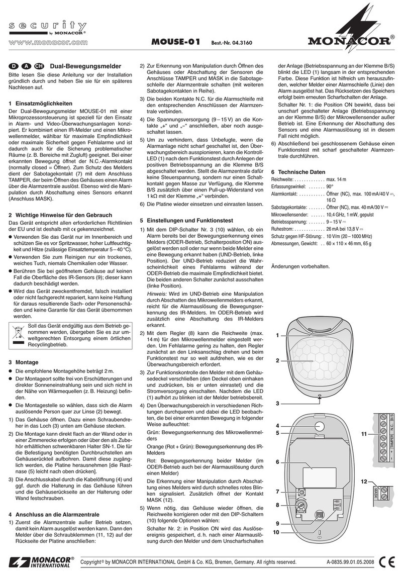
PIR-990 Codice 04.0060
Copyright©by MONACOR INTERNATIONAL GmbH & Co. KG, Bremen, Germany. A rights reserved. A-0851.99.01.05.2008
I
®
®
Segnalatore i movimento PIR
Vi preghiamo di leggere attentamente le presenti istru-
zioni prima dellʼinstallazione e di conservarle per un
uso futuro.
1Possibilità ʼimpiego
Il segnalatore di movimento PIR-990 (passivo infra-
rosso) è stato realizzato specialmente per lʼimpiego in
impianti dʼallarme e sorveglianza video. Se viene rico-
nosciuto un movimento, il contatto dʼallarme apre o
chiude (a scelta). Una resistenza 3,9 kΩ integrata può
essere utilizzata per il collegamento di una linea di
segnalatori. La sensibilità può essere regolata in modo
tale che animali domestici di passaggio non fanno
scattare lʼallarme. Come protezione del segnalatore è
presente un contatto antisabotaggio (7), che segnala
alla centralina dʼallarme lʼapertura del contenitore.
2 Avvertenze importanti per lʼuso
Questʼapparecchio è conforme a tutte le direttive
richieste dellʼUE e pertanto porta la sigla .
GUsare lʼapparecchio solo allʼinterno di locali e pro-
teggerlo dagli spruzzi dʼacqua, da alta umidità del-
lʼaria e dal calore (temperatura dʼimpiego ammessa
fra
-
10 e +50 °C).
GPer la pulizia usare solo un panno morbido, asciutto;
non impiegare in nessun caso prodotti chimici o
acqua.
GNon toccare in nessun caso la superficie del sensore
IR (8) quando il contenitore è aperto; altrimenti il sen-
sore potrebbe subire dei danni.
GNel caso dʼuso improprio, di installazione sbagliata o
di riparazione non a regola dʼarte dellʼapparecchio,
non si assume nessuna responsabilità per eventuali
danni consequenziali a persone o a cose e non si
assume nessuna garanzia per lʼapparecchio.
3 Montaggio
GLʼaltezza di montaggio dovrebbe essere fra 2 m e
3 m.
GIl luogo di montaggio dovrebbe essere libero di
scosse, radiazione diretta del sole e correnti dʼaria,
e non dovrebbe trovarsi nelle vicinanze di sorgenti
di calore (p. es. riscaldamento).
GScegliere il punto di montaggio in modo tale che la
persona che fa scattare lʼallarme si muova trasver-
salmente rispetto alla lente (2).
1) Svitare la vite (3) e aprire il contenitore.
2) Il montaggio può essere fatto direttamente contro la
parete o in un angolo, oppure per mezzo del sup-
porto girevole BR-990 disponibile come accesso-
rio. Per il fissaggio al supporto usare i due fori (4).
Aprire sul retro del contenitore gli altri punti previsti
per il fissaggio e come passacavi. Se necessario,
premere leggermente a destra la linguetta (9) e
togliere la scheda per rendere accessibili i punti di
passaggio.
3) Fare passare i cavi di collegamento nel contenitore
attraverso lʼapertura scelta e eventualmente attra-
verso il supporto, e quindi avvitare il retro del con-
tenitore al supporto o alla parete.
4) Rimettere la scheda fino allo scatto.
5) Se si usa il supporto, avvitarlo alla parete o al sof-
fitto e orientare il segnalatore di movimento verso la
zona da sorvegliare.
Se si desidera eliminare lʼapparecchio defini-
tivamente, consegnarlo per lo smaltimento
ad unʼistituzione locale per il riciclaggio.
4 Collegamento con
la centralina ʼallarme
Per prima cosa disattivare la centralina per non far
scattare un allarme. Quindi collegare il segnalatore
per mezzo dei morsetti a vite (6):
1) Inserire i due morsetti TAMPER nel circuito antisa-
botaggio della centralina (in serie con altri contatti
antisabotaggio).
2) Collegare i morsetti COM e NC per il circuito dʼal-
larme con i relativi contatti della centralina. Nellʼul-
timo segnalatore di una linea, al posto di un termi-
natore esterno si può usare la resistenza 3,9 kΩ
interna (cfr. i dati della centralina dʼallarme). In que-
sto caso collegare invece i morsetti COM e 3.9k.
Un terminatore definisce la corrente di riposo per
il controllo della linea. In caso di deviazione, la cen-
tralina può fare scattare un allarme.
3) Collegare lʼalimentazione (9 – 16 V ) con i morsetti
POWER (la polarità è indifferente), ma lasciarla
ancora spenta.
5 Impostazioni e test funzionale
1) La lente (2) suddivide la zona da sorvegliare in
64 zone. Con il jumper 1 (11) decidere se già con
lʼattraversamento di 2 zone deve scattare lʼallarme
oppure se occorrono 4 zone.
Per escludere un allarme da piccoli animali (fino
a 15 kg ca.) spostare il jumper 2 (11) da NORMAL
a HARSH.
2) Con il regolatore VR1 (10) è possibile impostare la
sensibilità e quindi la portata del sensore. Girare
dapprima il regolatore in posizione centrale e adat-
tarlo, se necessario, dopo il test funzionale.
3) Con il jumper 3 (11) decidere, se il contatto dʼal-
larme deve funzionare come contatto di riposo
(NC) o di lavoro (NO = NA) (descrizione della
centralina dʼallarme).
4) Per controllare le funzioni chiudere il segnalatore
con il suo coperchio e accendere lʼalimentazione.
Dopo 30 sec. ca. il LED (1, 5) smette di lampeg-
giare e il segnalatore è pronto per lʼuso.
5) Attraversare la zona da sorvegliare in varie dire-
zioni osservando il LED che si accende in caso di
riconoscimento di un movimento.
6) Alla fine eseguire un test funzionale con la centra-
lina attivata.
6 Dati tecnici
Portata: . . . . . . . . . . . 15 m con altezza di montaggio
di 2,4 m
Angolo di rilevamento: 100°
Contatto dʼallarme: . . Contatto di riposo (NC) o
di lavoro (NA),
max. 100 mA/30 V
Terminatore: . . . . . . . 3,9 kΩ (opzionale)
Contatto
antisabotaggio: . . . . . di riposo (NC),
max. 100 mA/30 V
Alimentazione: . . . . . 9 – 16 V /max. 20 mA
Temperatura
dʼesercizio: . . . . . . . .
-
10 a +50 °C
Dimensioni: . . . . . . . . 70 mm × 110 mm × 48 mm
Peso:.............82g
Con riserva di modifiche tecniche.
1
2
3
4
5
6
7
8
9
10
11
4
This manual suits for next models
1
Table of contents
Languages:
Other Monacor Security Sensor manuals

Monacor
Monacor IF-15 User manual

Monacor
Monacor PIR-100P User manual

Monacor
Monacor PIR-100D User manual

Monacor
Monacor S-230A User manual

Monacor
Monacor MOUSE-01 User manual

Monacor
Monacor SOUTDOOR-L User manual

Monacor
Monacor PIR-100 User manual

Monacor
Monacor IRS-200 User manual

Monacor
Monacor SMILE-16 User manual

Monacor
Monacor security MOUS-01 User manual