Envirco MAC 10 VE5 RSR Manual

Updated 7/05
*** READ AND SAVE THESE INSTRUCTIONS ***
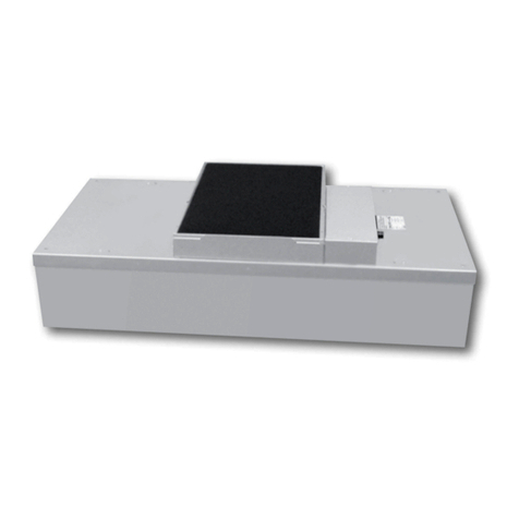
MAC 10Original VE5FAN FILTER MODULE
INSTALLATION AND SERVICE MANUAL
STANDARD, RSR, RSRE MODELS
Mac 10and VE5are registered Trademarks of the
Envirco Corporation, Albuquerque, New Mexico, U.S.A.
US Patents 4,560,395 and 5,470,363 Other patents issued and pending in foreign countries

MAC 10 Original VE5 SERVICE MANUAL
PAGE 1
READ AND SAVE THESE INSTRUCTIONS
WARNING!
TO REDUCE THE RISK OF FIRE, ELECTRICAL SHOCK, OR INJURY TO PERSONS,
OBSERVE THE FOLLOWING :
A. Installation work and electrical wiring must be done by qualified person(s) in
accordance with all applicable codes and standards, including fire-rated
construction.
B. When cutting or drilling into wall or ceiling, do not damage electrical wiring and
other hidden utilities.
C. If this unit is to be installed over a tub or shower, it must be marked as appropriate
for the application.
D. Use this unit only in the manner intended by the manufacturer. If you have any
questions, contact the manufacturer:
ENVIRCO CORPORATION FEDDERS INTERNATIONAL
Envirco Office Headquarters
5601 Balloon Fiesta Parkway N.E. No. 728 Fuzhou Road
Albuquerque, New Mexico 87113 Haungpu District
U.S.A. Shanghai 200001 PRC
Tel : (505) 345-3561 Tel : (86) 512 6258 7180
Fax : (505) 345-8875 Fax : (86) 512 6258 0035
TRION LTD. FEDDERS INTERNATIONAL,
INC.
The Cavendish Centre DP Computers Building
Winnall Close 128 Joo Seng Road #05-01
Winchester, Hampshire, SO23 0LB, UK Singapore 368356
Tel : 44 1962 840465 Tel : 65 286 0995
Fax : 44 1962 828619 Fax : 65 286 0859
E. Before servicing or cleaning unit, switch power off at service panel and lock service
panel to prevent power from being switched on accidentally.

MAC 10 Original VE5 SERVICE MANUAL
PAGE 2
Table of Contents
Title Page
I. SERVICE: CLEANING THE MAC 10 VE5 PREFILTER.............................3
II. SERVICE: REMOVAL AND REPLACEMENT OF THE HEPA/ULPA
FILTER (STANDARD UNIT)...............................................................................4
III. SERVICE: REMOVAL AND INSTALLATION OF THE ROOM SIDE
REPLACEABLE FILTER (RSR/RSRE) ..............................................................5
IV. SERVICE: REMOVAL AND INSTALLATION OF THE MOTOR
(STANDARD AND RSR MODELS) ....................................................................7
V. SERVICE: REMOVAL AND INSTALLATION OF THE RSRE MOTOR...9
VI. ON/OFF SWITCH -SPEED/AIRFLOW ADJUSTMENT ..........................11
VII. TROUBLE SHOOTING:...........................................................................12
VIII. MAC 10 VE5 WIRING DIAGRAMS.......................................................13
IX. MAC 10 VE5 REPLACEMENT PARTS LIST: .........................................14
VII. LIMITED WARRANTY.............................................................................15
X. TESTING..................................................................................................15

MAC 10 Original VE5 SERVICE MANUAL
PAGE 3
I. SERVICE: Cleaning the MAC 10 VE5 Prefilter
WARNING!
Disconnect the unit from the electrical power source before attempting any
service.
Tools Required: None
Note: To keep the filter in top operating condition, washing the foam prefilter is
recommended every three to six months.
Step 1. To gain access to the prefilter, remove the ceiling panel next to the unit, if
applicable.
Step 2. Switch the ON-OFF switch to the off position.
Step 3. Remove the prefilter from the snap-in frame.(see Figure 1)
Step 4. Clean the prefilter by hand washing in water with a mild detergent or by using
a vacuum cleaner. Allow prefilter to dry completely before replacing.
Step 5. Reassemble by reversing the above steps.

MAC 10 Original VE5 SERVICE MANUAL
PAGE 4
. Figure 1
II. SERVICE: Removal and Replacement of the HEPA/ULPA
Filter (Standard Unit)
WARNING!
Disconnect the unit from the electrical power source before attempting any
service.
Tools Required: Phillips Head Driver
Step 1. Remove unit from ceiling.
Step 2. Remove the 10 screws holding the HEPA/ULPA filter to the lid assembly.
Step 3. Lift the lid assembly off the HEPA/ULPA filter (see Figure 2). Discard the used
filter as per requirements of the applicable regulations.
Note: Before replacing with a new HEPA/ULPA filter, carefully inspect the new filter for
any visible damage. Also inspect the gasket in the “tee” bar to insure a tight seal.
Replace as necessary.
Step 5. Replace with the new HEPA/ULPA filter and assemble by reversing the above
steps.
Figure 2
Lid Assembly
Prefilter
HEPA/ULPA
Filter

MAC 10 Original VE5 SERVICE MANUAL
PAGE 5
III. SERVICE: Removal and Installation of the Room Side
Replaceable Filter (RSR/RSRE)
WARNING!
Disconnect the unit from the electrical power source before attempting any
service.
Tools Required: 7/16” hex head wrench
4” x 4” x 3/8” filter support blocks
Manpower Required: 2
Step 1. Remove the diffuser screen by shifting it to one side and lowering it out of the
housing.
Step 2. Install filter support blocks in all four corners of the unit. These blocks slide
into place and support the filter during the removal process.
Step 3. Remove the six screws and clips, remove filter blocks and lower the filter as
shown in Figure 3.
Step 4. Inspect filter for visible damage, if damaged set aside for replacement or
repair.
Step 5. Place the filter against the filter-sealing surface of the RSR unit. Install the four
filter support blocks as previously described.
Step 6. Install filter clips and screws, hand tight (until gasket compression begins) in
the order shown in Figure 4. After all six clips are hand tight, tighten screws to
create 50% compression (0.25”) on the gasket, using the same order.
Step 7. Remove filter support blocks and reinstall screen.
Note: Tighten filter clip bolts as necessary to insure no bypass leakage. DO NOT over
tighten.
Figure 3
Filter Clip
and Bolt
Fan
Filter
RSR Filter
Diffuser Screen

MAC 10 Original VE5 SERVICE MANUAL
PAGE 6
Figure 4
4
1
2
3
5
6

MAC 10 Original VE5 SERVICE MANUAL
PAGE 7
IV. SERVICE: Removal and Installation of the Motor (Standard
and RSR models) WARNING!
Disconnect the unit from the electrical power source before attempting any
service.
WARNING!
Electrical service should be performed by licensed electricians or authorized
ENVIRCO service technicians.
Tools Required: Phillips Head Driver
3/8” (10mm) Hex Head Wrench
Pliers
5/32”(0.40 cm) Allen wrench
Step 1. To gain access to the motor, remove the ceiling panel next to the unit, if
applicable.
Step 2. Switch the ON-OFF switch to the off position.
Step 3. Remove the prefilter off the prefilter frame.(see Section II)
Step 4. Loosen the electrical box cover screws (2), and slide/lift off cover.
Step 5. Make note of all wire locations for reinstallation later.
Step 6. Disconnect the two brown wires from the capacitor, using a pair of pliers.
Step 7. Disconnect the motor wiring from the rotary switch and rocker switch or speed
control and rocker switch and remove the grommet from the motor leads.
Save this grommet for reinstallation.
Step 8. Remove the six screws to free the venturi ring and remove the motor/blower
assembly from the lid assembly. If using a power drivers, set the unit to a low
torque setting to avoid stripping the sheet metal screws.(see Figure 5)
Step 9. Using a 5/32”(0.40 cm) Allen wrench remove the blower wheel from the motor
shaft. Remove motor from the venturi ring using a hex wrench.
Step 10.Replace with the new motor and reassemble by reversing the above steps. Set
the spacing between the venturi ring and the blower wheel at 0.06”(0.15 cm)
clearance.

MAC 10 Original VE5 SERVICE MANUAL
PAGE 8
Figure 5
Disconnect motor leads from capacitor,
ON/OFF switch, and three-speed switch
or speed control.
Prefilter
Motor
Venturi Ring
Blower Wheel

MAC 10 Original VE5 SERVICE MANUAL
PAGE 9
V. SERVICE: Removal and Installation of the RSRE Motor
WARNING!
Disconnect the unit from the electrical power source before attempting any
service.
WARNING!
Electrical service should be performed by licensed electricians or authorized
ENVIRCO service technicians.
Step 1. To gain access to the motor, remove the gel seal filter (see Section III).
Step 2. While supporting the baffle assembly from below, remove the four corner
screws on the baffle assembly and lower the assembly.(see Figure 6)
Step 3. Prior to removing motor/blower assembly, remove electrical box cover (located
underneath the lid panel) to expose motor connectors. Disconnect the power.
Step 4. While supporting the motor/blower assembly from below, remove the eight
screws on the motor plate and lower the motor/blower assembly.(see Figure 7)
Figure 6
Gel Seal Filter
Lid Panel
Motor Plate
(Motor/Blower Assy)
Electrical connectors located
on inner prefilter wall
Plenum
Baffle Assembly

MAC 10 Original VE5 SERVICE MANUAL
PAGE 10
Step 4. Remove the six screws to free the venturi ring and remove the motor/blower
assembly from the motor plate.(see Figure 9)
Step 5. Using a 5/32”(0.40 cm) Allen wrench remove the blower wheel from the motor
shaft. Remove motor from the venturi ring by remove the three # 10 bolts.
Step 6. Before removal of the motor mount bracket, measure the precise location of
the bracket on the motor. Remove the bracket.
Step 7. Replace with the new motor and reassemble by reversing the above steps. Set
the location of the motor mount bracket as measured (see above Step 6). Set
the spacing between the venturi ring and the blower wheel at 0.06”(0.15 cm)
clearance. When reinstalling the motor plate, align the plate to insure that the
leads will reach the electrical box.
Figure 7
Blower Wheel
Venturi Ring
Motor
Motor Plate
Machine Screw
Grommet
Wellnut

MAC 10 Original VE5 SERVICE MANUAL
PAGE 11
VI. ON/OFF Switch -Speed/Airflow Adjustment
All MAC 10 units are equipped with a three-position rotary switch, which is located on
the side of the electrical box.(see Figure 8)
Recommended fan speed during initial start-up and operation is the “LOW” speed. As
airflow eventually decreases due to filter loading, fan speed may be increased by
moving the rocker switch to the top or “MEDIUM” position, and finally to the “HIGH”
position. Periodic airflow velocity readings(Per I.E.S. Specifications) should be
conducted to determine the filter condition and appropriate fan speed setting.
Figure 8
Optional Speed Control
Units furnished with the optional speed control (the speed control is standard with 2x2
and 2x3 units) enable adjustment of airflow at any setting within the recommended
performance range. The speed control knob is located on the side of the electrical box,
adjacent to the on/off switch.
Figure 9
Airflow/speed is adjusted by rotating the knob (see Figure 9):
Clockwise àLowers the speed
Counter-Clockwise àIncreases the speed
Fully rotating the speed control knob to the left or counter-clockwise will turn the unit
off.
ON/OFF SwitchElectrical EntranceSpeed Control
ON/OFF SwitchElectrical Entrance3-Speed
Switch

MAC 10 Original VE5 SERVICE MANUAL
PAGE 12
Note : When turning the unit “ON” from the “OFF” position of the speed control, the fan
is at the highest speed. Turning the speed control knob clockwise will lower the airflow.
VII. Trouble Shooting:
Low Air Velocity
Step 1. Check prefilter media; replace or clean as necessary.
Step 2. Flip switch from “Low” to “Medium” or “Medium” to “High” on units with 3-speed
switch.
Step 3. Adjust variable speed control (only units with optional Speed Control) for
higher blower output.
Step 4. Check power supply for proper voltage, amperage and distribution frequency.
Step 5. Replace HEPA/ULPA filter if the air velocity remains low.
High Air Velocity
Step 1. Flip switch from “HIGH” to “MEDUIM” to “LOW” on units with 3-speed switch.
Step 2. Adjust variable speed control (only units with optional Speed Control) for lower
blower output.
Non-Laminar Flow and/or Excessive Contamination
Step 1. Insure that no large obstructions are upstream of airflow pattern.
Step 2. Determine that no other air-moving devices are operating in or around clean
room which disrupt room’s airflow pattern.
Step 3. Check air velocity and if low, conduct the “Low Air Velocity” procedure outlined
above.
Step 4. Conduct smoke and photometer test on HEPA filter. Seal or replace HEPA
filter as necessary.

MAC 10 Original VE5 SERVICE MANUAL
PAGE 13
VIII. MAC 10 VE5 Wiring Diagrams
Figure 10
Figure 11
Standard Wiring for MAC 10
ON/OFF switch
Speed Control 10µCapacitor
Optional Wiring for MAC 10
With Speed Control

MAC 10 Original VE5 SERVICE MANUAL
PAGE 14
IX. MAC 10 VE5 Replacement Parts List:
Description Quantity ENVIRCO Part Number
per unit 115V 220V
277V
________________________________60 Hz___50 -60 Hz______60 Hz_______
Prefilter 162981-001 62981-001 62981-001
Motor 163764-001 63764-002 63764-003
Capacitor 161485 61485 61485
ON/OFF Switch 163739 63739 63739
Speed Control (Optional) 163011 63015 63016
(CE Marked) 63742
Pressure Switch (Optional) 63415 63415 63415
Transformer (Optional) 63667 63666 63665
Current Sensor (Optional) 24235-001 24235-001 24235-001
Power cord (Optional) 63042-001 63042-004 63042-013
Standard Filter: HEPA ULPA (Optional)
2’ x 2’ 169514-004 69514-018
2’ x 3’ 169514-019 69514-012
2’ x 3.5’ 169514-020 69514-021
2’ x 4’ 169514-006 69514-007
HEPA Filter (RSR):
2’ x 2’ 169391-005 69391-006
2’ x 3’ 169391-012 69391-013
2’ x 3.5’ 169391-010 69391-011
2’ x 4’ 169391-001 69391-002
Optional Accessories:
Fluorescent lighting
Ionizing bar
Solid state speed control on 2x4, and 2x31/2units -(standard on all other sizes)
12”(30.48 cm) diameter A/C intake collar
Gel Seal Filter (RSR unit only)
ULPA Filter (Standard and RSR)
Replacement parts are available through your authorized ENVIRCO representative. If
you cannot locate a representative in your area, contact our Parts Department at:
ENVIRCO CORPORATION
5601 Balloon Fiesta Parkway NE
Albuquerque, NM 87113, U.S.A.
Tel: (505) 798-4412
Tel: (800) 545-6598
Fax: (505) 345-8875

MAC 10 Original VE5 SERVICE MANUAL
PAGE 15
VII. LIMITED WARRANTY
ENVIRCO CORPORATION (“ENVIRCO”) warrants the equipment will be free of defects
in materials and workmanship under normal use for a period of three (3) years. The
HEPA filter shall only be warranted against loading for a period of two (2) years when
operated in cleanroom conditions. ENVIRCO’s sole obligation under this warranty is to
repair or replace any parts of the equipment which are defective for a period of three
(3) years from the invoice date, provided that the repair or replacement is actually
performed within the three(3) year period from the invoice date. The buyer agrees to
assume any incidental expenses including but not limited to the cost of transporting the
defective equipment to ENVIRCO’s repair facility. The buyer’s sole remedy under this
limited warranty is the repair or replacement of any defective part of the equipment.
ENVIRCO DISCLAIMS ANY IMPLIED WARRANTIES INCLUDING WARRANTIES OF
MERCHANTABILITY AND FITNESS FOR A PARTICULAR PURPOSE. In no event
shall ENVIRCO be liable for punitive, incidental, or consequential damages arising out
of this sale, including, but not limited to damage to persons or property, loss of use,
loss of time, inconvenience, equipment rental, loss of earnings or profit or any other
commercial loss. This warranty excludes certain expendable items such as light tubes,
prefilters, etc. ENVIRCO expressly disclaims and excludes from this warranty any
responsibility for equipment failures and/or defects attributable to improper
maintenance, abuse, accident or modification of the equipment (such as application of
an adjustable frequency drive).
X. TESTING
Each MAC 10 VE5 filter unit is thoroughly tested at the factory before shipment.
However, because of the “rigors” of shipping, ENVIRCO encourages its re-test after
installation.
ENVIRCO recommends that the customer contact an independent organization, with
technicians trained and experienced in performance evaluation and maintenance of
clean air equipment.
Some of the testing procedures performed on the MAC 10 VE5 include PS challenge of
HEPA filters to assure specified performance, along with air velocity measurement and
adjustment tests.
Recommended Testing
All units that are airflow tested at Envirco are tested using a Shortridge Airdata
Multimeter 800 series with a Velgrid head. The recommended method of
reading is to place one corner of the Velgrid head 1-1/4” from the corner of the
filter face and then take four reading evenly spaced along the four foot side, then
repeat these reads for the other long side. This gives a total of eight reading to
test the unit. All advertised data is based on using the Velgrid with 8 readings
(128 velocity points). Envirco recognized the using 8 reading during a

MAC 10 Original VE5 SERVICE MANUAL
PAGE 16
cleanroom start-up may be time consuming and recommends using 3 Velgrid
readings taken on a diagonal, as shown below.
Recommended Testing –8 readings with a Velgrid
Factory Approved Testing –3 readings with a Velgrid
This manual suits for next models
2
Table of contents
Other Envirco Water Filtration System manuals
Popular Water Filtration System manuals by other brands
Trox Technik
Trox Technik MFI-Ex Installation and maintenance manual
Eljen
Eljen Mantis M5 Series Installation and System Design Guide
Neptun
Neptun Classic NCTF-O 8000 operating instructions
CALEFFI
CALEFFI DISCAL 5517 Series Installation, commissioning and servicing instructions
Vortec
Vortec THREAD GUARD 424 Operation & Safety Instructions
Hydac
Hydac FluidAqua Mobil FAM 15 Maintenance instructions
