maintenance
The Thread Guard has no moving parts and can be
disassembled for cleaning.
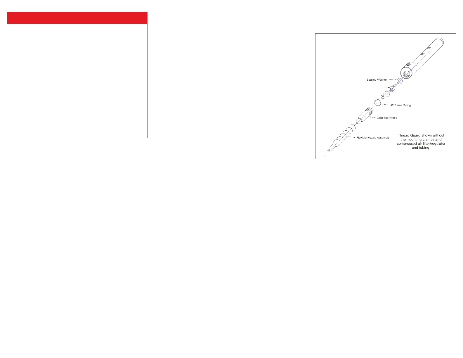
1. Remove the black cold air outlet tting with a spanner
wrench.
2. Remove the small O-ring, plastic bushing, brass
generator and thin plastic “washer”.
3. Clean all parts especially the six small orices in the
brass generator.
4. Reassemble in the reverse order (thin plastic washer
rst, then the generator, bushing and O-Ring).
5. Tighten the cold air outlet tting to 50 in-lbs or more.
6. If the orices in the generator require frequent cleaning,
this indicates that the compressed air is not being
ltered or the lter element requires changing.
7. Change the lter element as needed.The lter/regulator
supplied with some Thread Guard models utilizes a 5
micron element.
8. Be sure to shut off the compressed air supply to the
lter before attempting to change the element or before
any maintenance.
1. Do not operate a Thread Guard at compressed air
pressures above 150 psig (10.3 Bar).
2. Do not operate a Thread Guard at compressed air
temperatures above 110oF (43oC).
3. Avoid direct contact with compressed air.
4. Do not direct compressed air at any person.
5. When using compressed air, wear safety glasses
with side shields.
NOTE: There is no need to limit compressed air pressure
to a maximum of 30 psig (2 bar). It is not possible to
block the ow of air from the Thread Guard to register 30
psig (2 bar) on a test gauge.
tHreaD GuarD®aSSembLy
LimiteD warranty
Vortec compressed air products manufactured by ITW Air
Management will be replaced or repaired if found to be
defective due to manufacture defect within ten years from
the date of invoice.
Refer to our website www.pelmareng.com for full
warranty details and limitations. ITW Air Management
makes no specific warranty merchantability or warrant of
fitness to a particular purpose.
Insufficient airow may be caused by the following:
1. Undersized compressed air line size.
2. Compressed air pressure too low.
3. Partial or complete blockage of internal compressed air
path, due to dirt. See Maintenance section for cleaning
instructions; and Compressed Air Supply section for
lter recommendations.
4. Loose cold cap. This may occur if not tightened properly
after disassembled for cleaning.
If trouble persists, please contact Vortec at
888-754-6329
trOubLeSHOOtinG
The compressed air supply must be ltered to remove
water and dirt using a 5 micron or smaller lter. A
combination lter/regulator is included with some Thread
Guard models to accomplish this. If oil is present in the
compressed air supply, remove the oil using a 0.01 micron
(maximum) coalescing air lter. Failure to use a lter may
cause clogging (and freezing) of the compressed air paths
inside the Vortec product. Filter recommendations are
given in Table 1.
Filter elements must be changed on a regular basis.
Frequency of change is determined by the condition of
the compressed air supply. Filters should be installed in
the compressed air supply line as close as possible to the
Vortec product.
The appropriate size of compressed air supply line should
be selected to ensure optimal performance of the Vortec
product. Please refer to Table 2 to determine what supply
line size is recommended for your application.
Contact Vortec at 1-800-441-7475 for further assistance.
cOmpreSSeD air SuppLy
inStaLLatiOn anD OperatiOn
1. Use two supplied mounting clamps to attach the Thread
Guard to an appropriate location on your machine.
Do not block either of the hot exhaust holes with the
mounting clamps.
2. Mount the lter/regulator (if supplied) to a xed 1/8”pipe
so that the lter bowl points downward.
3. Cold airow and temperature can be changed by
adjusting the pressure regulator (if included or supplied
separately) in the compressed air supply.
4. Set the pressure regulator to the lowest pressure that
permits adequate cooling of the needle.
intrODuctiOn
The Thread Guard is designed to use ltered compressed
air to cool needles on commercial sewing machines without
the use of any refrigerants. The Thread Guard consumes
8 SCFM of compressed air at 100 psig and approximately
5 SCFM if operated at 60 psig.
Model 424
(Drawings shown below are not to scale)
8H Bushing (see Table 1)
8 cfm Generator (see Table 1)
GeneraL Safety cOnSiDeratiOnS
warninG: cOmpreSSeD air cOuLD cauSe
DeatH, bLinDneSS Or injury


