Eljen Mantis M5 Series Guide

DRAFT
System Design & Installation Manual
www.eljen.com
CORPORATION
Innovative Environmental Products & Solutions Since 1970
TM
Vermont
November 2015

2015 Vermont Mantis M5Design & Installation Manual Page 2 www.eljen.com
Table of Contents
Topic
Page
Numbers
Glossary of Terms
3
Mantis M5Series General Description
4
1.0 General System Information
7
2.0 Systems for Level Sites
10
3.0 Systems for Sloped Sites
10
4.0 Trench Installation Guidance
11
5.0 Bed Systems Installation Guidance
13
6.0 Mound System Installation Guidance
15
7.0 Pumped System Guidance
18
8.0 System Ventilation Guidance
19
9.0 Recommended Notes on Design Plans
21
Tables
Table 1 Specified Sand Sieve Requirements
3
Table 2 Mantis M5 Trench Sizing Table
5
Table 3 Mantis M5 Bed Sizing Table
6
Mantis M5Drawings
Fig. 1 Mantis M5Components
4
Fig. 2 Mantis M5Series Cross Section
9
Fig. 3 Mantis M5Series Plan View
10
Fig. 4 Mantis M5Multiple Trench Cross Section
12
Fig. 5 Mantis M5Multiple Trench Plan View
12
Fig. 6 Mantis M5In-Ground Bed System Cross Section
14
Fig. 7 Mantis M5Bed System Plan View
14
Fig. 8 Mantis M5Raised or Fill Bed System Cross Section
17
Fig. 9 Mantis M5Sloped Bed System Cross Section
17
Fig. 10 Mantis M5Series Pressure Distribution –Orifice Layout
18
Fig. 11 Mantis Series Venting Diagram
19
Fig. 12 Mantis Series 2” By-Pass Line
19
Fig. 13 Mantis Series 2” By-Pass Line, Close Up
20

2015 Vermont Mantis M5Design & Installation Manual Page 3 www.eljen.com
Glossary of Terms
Mantis M5Series Units The Mantis M5Series units come preassembled and are 5 feet in length (as measured
from the Support Distribution Pipe) and 12” high. 12” and 24” wide models are available.
The 12” wide model is designated the Mantis M5.1, and the 24” wide model is the Mantis
M5.2. All models have 6” of specified sand under and to the sides of the product. 1” of
specified sand is placed over the units prior to backfill.
Support Distribution Pipe The Mantis M5Series Support Distribution Pipe is 5 feet in length and constructed from
crush resistant PVC Pipe. The pipes provide 3 pre-drilled one inch holes at specified
spacing located at the 12, 5 and 7 o’clock position.
Filter Support Module There are 5 Filter Support Modules for each M5unit. All Filter Support Modules are 4”
thick. The 5.1 model is 12” wide and the 5.2 model is 24” wide.
Specified Sand The Specified Sand envelope around the Mantis M5Series (6” minimum underneath, 6”
minimum on the sides, 1” minimum on the top, and 8” in-between the Support Modules)
shall meet the requirements as indicated in the Specified Sand Requirements chart listed
in Table 1 listed below. This sand is a WASHED CONCRETE SAND OR VERMONT 1-
913(C)2 SAND FROM THE REGULATIONS, WITH LESS THAN 10% PASSING #100
SIEVE AND LESS THAN 5% PASSING A #200 SIEVE.
Note: Specified Sand under the Mantis M5units must be stabilized so differential settling
does not occur over time. This can be accomplished by using a mechanical or hand
methods. Specified Sand between the modules must be stabilized using a tamping rod.
Please contact Eljen Corporations Technical Services Department if more information is
needed.
Ask your material supplier for a sieve analysis to verify that your material meets the
required specifications.
Table 1: SPECIFIED SAND SIEVE REQUIREMENTS
Eljen Mantis M5Series
Specified Sand Requirements
Sieve Size
Sieve Square
Opening Size
Specification
Percent Passing
(Wet Sieve)
0.375”
9.5 mm
100.0
#4
4.75 mm
95.0 –100.0
#8
2.36 mm
80.0 –100.0
#16
1.18 mm
50.0 –85.0
#30
600 µm
25.0 –60.0
#50
300 µm
5.0 –30.0
#100
150 µm
< 10.0
#200
75 µm
< 5.0
Request a sieve analysis from your material supplier to ensure that
the system sand meets the specification requirements listed above.
Design Flow The estimated design flow used to size a system is 70 gallons per day per person. For
the first 3 bedrooms of a home, it is assumed that there are 2 people per bedroom. For
each additional bedroom, there is 1 person per bedroom. Minimum design is a 2 bedroom
home or 280 gpd for residential systems.

2015 Vermont Mantis M5Design & Installation Manual Page 4 www.eljen.com
Mantis M5General Description
Note: To receive design standards for specially engineered dosing systems or commercial systems, contact Eljen’s Technical Resource Department at
1-800-444-1359. Mantis M5 series systems must be designed and constructed according to this Design & Installation Manual and the State of Vermont
Environmental Protection Rules, Chapter 1, effective September 29, 2007 (hereinafter the Regulations).
________________________________________________________________________________________________________________________
How the Mantis M5Series System Works
The Eljen Mantis M5Series is a wastewater disposal technology comprised of a proprietary filtering process that applies
clarified effluent to the soil. The Mantis M5Series performance is based on accepted industry principals of increasing the
receiving soils long term acceptance rate by keeping the biological growth off the native soils and within the system. This
technology utilizes 3 dimensional surface areas to improve effluent quality, resulting in greater reliability and ease of
operation.
•The Support Distribution Pipe provides internal distribution, a venting conduit for the system and secures the five
Filter Support Modules in place. This distribution pipe is centered within the Filter Support Module to distribute
septic effluent.
•Septic effluent is filtered through the Filter Support Modules. Each module consists of a cuspated core
surrounded by Bio-Matt geo-textile fabric. Its unique design provides increased surface area within each module.
This area is known as the Internal Surface Optimization envelope, ISO for short. The ISO envelope provides an
increased surface area that greatly exceeds the Filter Support Module’s footprint, a traditional gravel footprint or
that of a gravelless replacement technology.
•Open air channels within the modules support aerobic bacterial growth on the Filter Support Modules geotextile
fabric interface, surpassing the surface area provided by traditional absorption systems.
•Effluent is transferred into the Specified Sand layer which supports unsaturated flow into the native soil. This
Specified Sand and soil interface maintains soil structure while maximizing the available absorption of the native
soil.
•The Specified Sand layer also protects the soil from compaction and helps maintain existing pore spaces in the
soil. This preserves the soil’s natural infiltration capacity which is critical for long-term performance, especially in
finer textured soils.
FIGURE 1: MANTIS M5COMPONENTS

2015 Vermont Mantis M5Design & Installation Manual Page 5 www.eljen.com
Mantis M5Series Sizing
TABLE 2: Mantis M5Trench Sizing Table
Notes:
1.Minimum absorption area has been adjusted to reflect the maximum reduction of 50%.
2.Number of Mantis M5Series units is determined on the current application rates defined in the regulations.
3.For number of Mantis M55.2 units, divide by 15 ft² per unit and round up to the nearest whole number of units.
4.For number of Mantis M55.1 units, divide by 10 ft² per unit and round up to the nearest whole number of units.
5.The minimum number of bedrooms for residential designs shall be 2 bedrooms unless otherwise dictated by the
regulations.
Percolation
Rate
2 Bedroom
Minimum
Absorption Area
3 Bedroom
Minimum
Absorption Area
Additional Absorption
Area per Additional
Bedrooms over 3
Commercial Absorption
Area based on 100 gallons
of design flow per day
1 - 4 94 140 24 34
5 - 8 132 198 33 48
9 - 12 162 243 41 58
13 - 16 187 280 47 67
17 - 20 209 314 53 75
21 - 24 229 343 58 82
25 - 28 247 371 62 89
29 - 32 264 396 66 95
33 - 36 280 420 70 100
37 - 40 296 443 74 106
41 - 44 310 465 78 111
45 - 48 324 485 81 116
49 - 52 337 505 85 121
53 - 56 350 524 88 125
57 - 60 362 543 91 130
61 - 64 374 560 94 134
65 - 68 385 578 97 138
69 - 72 396 594 99 142
73 - 76 407 611 102 146
77 - 80 418 627 105 150
81 - 84 428 642 107 153
85 - 88 438 657 110 157
89 - 92 448 672 112 160
93 - 96 458 686 115 164
97 - 100 467 700 117 167
101 - 104 476 714 119 170
105 - 108 485 728 122 174
109 - 112 494 741 124 177
113 - 116 503 754 126 180
117 - 120 512 767 128 183

2015 Vermont Mantis M5Design & Installation Manual Page 6 www.eljen.com
Mantis M5Series Sizing
TABLE 3: Mantis M5Bed Sizing Table
Notes:
1.Minimum absorption area has been adjusted to reflect the maximum reduction of 50%.
2.Number of Mantis M5Series units is determined on the current application rates defined in the regulations
3.For number of Mantis M55.2 units, divide by 15 ft² per unit and round up to the nearest whole number of units.
4.For number of Mantis M55.1 units, divide by 10 ft² per unit and round up to the nearest whole number of units.
5.The minimum number of bedrooms for residential designs shall be 2 bedrooms unless otherwise dictated by the
regulations.
Percolation
Rate
2 Bedroom
Minimum
Absorption Area
3 Bedroom
Minimum
Absorption Area
Additional Absorption
Area per Additional
Bedrooms over 3
Commercial Absorption
Area based on 100 gallons
of design flow per day
1 - 4 117 175 30 42
5 - 8 165 248 42 59
9 - 12 203 304 51 73
13 - 16 234 350 59 84
17 - 20 261 392 66 94
21 - 24 286 429 72 103
25 - 28 309 464 78 111
29 - 32 330 495 83 118
33 - 36 350 525 88 125
37 - 40 369 554 93 132
41 - 44 387 581 97 139
45 - 48 405 607 102 145
49 - 52 421 631 106 151
53 - 56 437 655 110 156
57 - 60 452 678 113 162
61 - 64 467 700 117 167
65 - 68 482 722 121 172
69 - 72 495 743 124 177
73 - 76 509 763 128 182
77 - 80 522 783 131 187
81 - 84 535 802 134 191
85 - 88 548 821 137 196
89 - 92 560 840 140 200
93 - 96 572 858 143 205
97 - 100 584 875 146 209
101 - 104 595 893 149 213
105 - 108 607 910 152 217
109 - 112 618 927 155 221
113 - 116 629 943 158 225
117 - 120 640 959 160 229

2015 Vermont Mantis M5Design & Installation Manual Page 7 www.eljen.com
1.0 General System Information
1.1 TREATMENT FIELD SIZE AND NUMBER OF UNITS: System size will vary depending on design flow and soil analysis.
Tables 2 - 3 indicate the minimum number of Mantis units required for various soil percolation rates and design flows.
Groundwater mounding and linear loading rate analyses are required when designing a wastewater system in Vermont.
Please refer to the Vermont Wastewater System & Potable Water Supply Rules for more information.
1.2 NON-RESIDENTIAL BUILDINGS & RESIDENTIAL INSTITUTIONS: Commercial systems require different sizing and
design criteria as compared to residential systems. Please contact Eljen’s Technical Resource Department at 1-800-444-
1359 for more information on commercial systems.
1.3 DEPTH TO GROUND WATER OR RESTRICTIVE LAYER: As required by state regulations; a minimum of 3 feet of
separation distance from the bottom of the Mantis M5 unit to the seasonal high water table and 4 feet separation from the
bottom of the Mantis M5unit to bedrock. This distance is measured from the bottom of the Mantis M5unit and not from the
bottom of the sand layer.
1.4 SPECIFIED SAND SPECIFICATION FOR TRENCH AND BED SYSTEMS: The first 6 inches of Specified Sand
immediately under, between Filter Support Modules, between unit rows and around the perimeter of the Mantis M5Series
system must be a WASHED CONCRETE SAND (meeting the requirements of Table 1 of this Manual) OR VERMONT
1-913(C)2, WITH LESS THAN 10% PASSING A #100 SIEVE AND LESS THAN 5% PASSING A #200 SIEVE.
Note: Specified Sand under the Mantis M5units must be stabilized so differential settling does not occur over time. This can
be accomplished by using a mechanical or hand methods. Specified Sand between the modules must be stabilized using
a tamping rod. Please contact Eljen Corporations Technical Services Department if more information is needed.
1.5 VEHICULAR TRAFFIC AND PAVED AREAS OVER SYSTEM: All vehicular traffic is prohibited over the Mantis system.
This is due to the compaction of material required to support traffic loading. Compaction greatly diminishes absorption
below the system and reduces the void space that naturally exists in soils for oxygen transfer and water migration. For
shallow installations, light-weight track-mounted machines are best for setting the final grade. It is also permissible to back-
blade the soil to set final minimum cover.
1.6 INGROUND TRENCHES & BEDS: Distribution methods permitted for use with these Mantis M5systems are:
Gravity
Pump to d-box with timed dosing
Pipe-in-Pipe Pressure Distribution
1.7 SHALLOW PLACEMENT, ELEVATED, OR MOUND SYSTEMS: Distribution methods permitted for use with these
Mantis M5systems are:
Pump to d-box with timed dosing
Pipe-in-Pipe Pressure Distribution
Pump to d-box distribution: The d-box shall be placed to center feed the laterals so that no lateral would exceed 50’ (100’
total).
A maximum of 500 lf total is permitted for pump to d-box distribution. Pipe-in-pipe pressure distribution has no maximum
length.
Shallow placement, elevated or mound systems with a design flow of greater than 1000 gpd must utilize pipe-in-pipe
pressure distribution.

2015 Vermont Mantis M5Design & Installation Manual Page 8 www.eljen.com
1.0 General System Information
1.8 SYSTEM AREA SLOPE: The maximum ground slope shall not exceed 30% for wastewater systems on subdivided lots
in existence before June 14, 2002. The maximum ground slope shall not exceed 20% for wastewater systems on lots that
are subdivided on or after June 14, 2002. The limitation on maximum slope shall not apply to replacement systems that are
subject to the variance provisions of Section 1-806 of these Rules.
1.9 SYSTEM VENTING: Eljen mandates venting when the system has greater than 18” of cover material as measured
from the top of the unit to finished grade. This will ensure proper aeration of the units.
1.10 BACKFILL & FINISH GRADING: Complete backfill with a minimum of five inches of clean porous fill measured from
the top of one inch specified sand over the module. Backfill exceeding 18 inches measured from the top of the module
requires venting at the far end of the trench or bed. Use well graded sandy fill that is clean, porous and devoid of large
rocks. Do not use wheeled equipment over the system. A light track machine may be used. Divert surface runoff from the
soil treatment area. Finish grade to prevent surface ponding. Seed and loam system area to protect from erosion.
1.11 EFFLUENT FILTERS: Effluent filters are recommended as a means of preventing solids from leaving the tank.
1.12 DISTRIBUTION PIPE LAYOUT: No additional distribution pipe is needed to connect units to one another. The support
distribution pipe runs through the center of the units and provides distribution for all configurations. For bed systems, the
distal ends of rows may be connected with non-perforated pipe.
1.13 GARBAGE DISPOSALS: The use of a garbage disposal is not recommended as they can cause septic system
problems by generating an increased amount of suspended solids, grease and nutrients. Design drawings shall include a
note “Garbage disposals shall not be used with this system”.
State regulations require that the system is upsized by 25%
NOTE: Eljen recommends the use of septic tank outlet effluent filters on all systems, especially on those systems that a
garbage disposal is installed, even if the tanks design capacity has been increased. Filters with higher filtration are
recommended for systems with garbage disposals.
1.14 ADDITIONAL FACTORS EFFECTING RESIDENTIAL SYSTEM SIZE: Homes with expected higher than normal
water usage should consider increasing the septic tank volume as well as increasing the size and number of units in the
disposal area. For example: Homes with tubs holding more than 100 gallons or utilizing other high use fixtures and
homes with higher than normal occupancy should consider septic tank and drain field modifications.
1.15 WATER SOFTENERS OR CONDITIONERS: Discharge of water softener or conditioner backwash to Eljen Products
is not allowed. Discharge from these devices shall be into a separate disposal system meeting the requirements of State
and Local Regulations.
1.16 PLANS AND SPECIFICATIONS: Typical treatment system drawings and specifications are shown at the end of this
manual. When used in conjunction with a permit sketch, site specific specifications, and manufacturer installation criteria,
these documents will normally be sufficient to assure a system can be properly installed. In some instances where a
complex system is encountered, formal plans and specifications may be required. This determination is left to the
discretion of the District Health Department.

2015 Vermont Mantis M5Design & Installation Manual Page 9 www.eljen.com
1.0 General System Information
FIGURE 2: MANTIS M5CROSS SECTION
36"
SPECIFIED SAND
TOPSOIL
CLEAN BACKFILL
VEGETATIVE COVER
ø 4" WITH
HOLESAT 12,
5 & 7 O'CLOCK
6" MIN
24"
6"
1"
8" MIN
6"
MANTIS 5.2
24"
SPECIFIED SAND
TOPSOIL
CLEAN BACKFILL
VEGETATIVE COVER
ø 4" WITH
HOLESAT 12,
5 & 7 O'CLOCK
6" MIN
12"
6"
1"
8" MIN
18"
MANTIS 5.1
12"
18"
12"
6"
FIGURE 3: MANTIS M5PLAN VIEW
60"
8" 4"
24"
60"
8" 4"
12"
MANTIS 5.2 MANTIS 5.1

2015 Vermont Mantis M5Design & Installation Manual Page 10 www.eljen.com
2.0 Design for Level Sites
2.1 BED/MOUND SYSTEMS ROW SPACING: Design level in-ground or raised systems with a minimum of 12-inches of
spacing between unit rows. The Mantis M5units and Specified Sand must be installed level at their design elevations.
2.2 TRENCH ROW SPACING: The minimum separation shall be 4’ of naturally occurring, undisturbed soil between
adjacent absorption trenches. The Mantis M5units and Specified Sand must be installed level at their design elevations.
3.0 Design for Sloped Sites
3.1 BED/MOUND SYSTEM ROW SPACING: Design level in-ground or raised systems with a minimum of 12-inches of
spacing between units. The Mantis M5units and Specified Sand must be installed level at their design elevations.
3.2 TRENCH ROW SPACING: The minimum separation shall be 4’ of naturally occurring, undisturbed soil between
adjacent absorption trenches. The Mantis M5units and Specified Sand must be installed level at their design elevations.

2015 Vermont Mantis M5Design & Installation Manual Page 11 www.eljen.com
4.0 Trench Installation Guidance
1. Carefully lay out all boundaries defining the location and elevation for all system components.
2. Prepare the site according to state and local regulations. Do not install a system on frozen or saturated soils. Take
precautions not to compact or smear the area with heavy machinery.
3. Plan all drainage requirements above (up-slope) the system and set soil grades to insure storm water drainage and
surface water is diverted away from the absorption area once the system is complete.
4. Excavate a minimum thirty-six inch (36”) wide level trench for the Mantis 5.2 unit or a minimum twenty-four inch (24”)
wide level trench for the Mantis 5.1 unit. Remove all organic soil, roots, and rocks within the absorption trench area.
5. Scarify receiving layers including sidewalls to eliminate soil smearing. Once scarifying is completed, avoid walking over
prepared absorption area until the Specified Sand has been placed on the bottom of the trench.
6. Place, compact, and rake a minimum 6” level layer of Specified Sand along the trench bottom. Specified Sand must
meet the minimum requirements listed on Table 1 of this manual. Ask your material supplier for a sieve analysis report
to verify that the sand you are going to install meets this specification. A hand tamper or a vibratory plate compactor is
sufficient for stabilization of the Specified Sand layer.
7. Center the Mantis units in the trench with the fabric side up, adjust the Filter Support Modules to ensure they are spaced
evenly and have not shifted during placement.
8. Connect the units by inserting the Support Distribution Pipe to one another. Direction changes are accomplished by
using a variety off the shelf fittings.
9. Install a termination cap or vent piping if required at the distal (far) end of the distribution pipe.
10. Begin placing Specified Sand between the Filter Support Modules and to the sides of the units.Specified Sand must
be placed lightly and may be accomplished with a backhoe or other suitable equipment. DO NOT dump full loads of
Specified Sand directly on the units.
11. Steps for placement of Specified Sand.
a. Starting at the top center of the units, use a minimal amount of Specified Sand necessary to set in place
the bottom section of the Filter Support Modules at their correct spacing.
b. Stabilize the sand that is in-between the Filter Support Modules with a tamping tool. Ensure that the void
area under the Support Distribution Pipe is filled and compacted with Specified Sand.
c. Additional Specified Sand is lightly added between the Filter Support Modules and along the sides of the
Mantis units to bring the sand fill 1-inch above the Filter Support Modules to account for sand settling.
d. Continue to moderately tamp and compact the sand that is in-between the Filter Support Modules. Spread
additional Specified Sand as necessary.
12. Set distribution box to the proper elevation to achieve a 1/8”drop per foot to the first unit. Make the connection to the
beginning of the first unit from the distribution box with SDR-35 pipe or equivalent.
13. Complete backfill over the Mantis M5units followed by topsoil to a depth of 6” –18” as measured from the top of the
units. 1” of the fill is Specified Sand, immediately on top of the unit. Systems with total cover that exceeds 18” as
measured from the top of the units to finished grade shall be vented at the distal (far) end of the system. Backfill material
shall be well graded sandy fill; clean, porous, and devoid of large rocks. Divert surface runoff with diversion ditches or
berms. Finish grade to prevent surface ponding. Seed or sod excavated areas to protect against erosion. Do not drive
or pave over the absorption area.
2015 Vermont Mantis M5Design & Installation Manual Page 12 www.eljen.com
4.0 Trench Installation Drawings
FIGURE 4: MANTIS M5MULTIPLE TRENCH CROSS SECTION
SPECIFIED SAND
NATIVE
SOIL
6" 24"
SPECIFIED SAND
12"
6"
SPECIFIED SAND
6" MIN COVER
INCLUDES 1" OF SPECIFIED SAND
NATIVE
SOIL
6" 24"
SPECIFIED SAND
18"
PER
PRODUCT
6"
6" MIN COVER
INCLUDES 1" OF SPECIFIED SAND
MANTIS 5.1
MANTIS 5.2
PER
PRODUCT
FIGURE 5: MANTIS M5MULTIPLE TRENCH PLAN VIEW
NATIVE SOIL
SEPTIC
TANK
PER DESIGN
6"
PER DESIGN
DISTRIBUTION BOX
SPECIFIED SAND

2015 Vermont Mantis M5Design & Installation Manual Page 13 www.eljen.com
5.0 Bed Systems Installation Guidance
1. Carefully lay out all boundaries defining the location and elevation for all system components.
2. Prepare the site according to state and local regulations. Do not install a system on frozen or saturated soils. Take
precautions not to compact or smear the area with heavy machinery.
3. Plan all drainage requirements above (up-slope) the system and set soil grades to insure storm water drainage and
surface water is diverted away from the absorption area once the system is complete.
4. Excavate the bed area. Remove all organic soil, roots, and rocks within the absorption area.
5. Scarify receiving layers including sidewalls to eliminate soil smearing. Once scarifying is completed, avoid walking over
prepared absorption area until the Specified Sand has been placed on the bottom of the absorption area.
6. Place, compact, and rake a minimum 6” level layer of Specified Sand along the trench bottom. Specified Sand must
meet the minimum requirements listed on Table 1 of this manual. Ask your material supplier for a sieve analysis report
to verify that the sand you are going to install meets this specification. A hand tamper or a vibratory plate compactor is
sufficient for stabilization of the Specified Sand layer.
7. Place the Mantis units in their rows with the fabric side up, adjust the Filter Support Modules to ensure they are spaced
evenly and have not shifted during placement.
8. Connect the units by inserting the Support Distribution Pipe to one another. Direction changes are accomplished using
a variety of off the shelf fittings.
9. Install a termination cap or vent piping if required at the distal (far) end of the distribution pipe.
10. Begin placing Specified Sand between the Filter Support Modules and to the sides of the units. Specified Sand must
be placed lightly and may be accomplished with a backhoe or other suitable equipment. DO NOT dump full loads of
Specified Sand directly on the units.
11. Steps for placement of Specified Sand.
a. Starting at the top center of the units, use a minimal amount of Specified Sand necessary to set in place
the bottom section of the Filter Support Modules at their correct spacing.
b. Stabilize the sand that is in-between the Filter Support Modules with a tamping tool. Ensure that the void
area under the Support Distribution Pipe is filled and compacted with Specified Sand.
c. Additional Specified Sand is lightly added between the Filter Support Modules and along the sides of the
Mantis units to bring the sand fill 1-inch above the Filter Support Modules to account for sand settling.
d. Continue to moderately tamp and compact the sand that is in-between the Filter Support Modules. Spread
additional Specified Sand as necessary.
12. Set distribution box to the proper elevation to achieve a 1/8” drop per foot to the first unit. Make the connection to the
beginning of the first unit row from the distribution box with SDR-35 pipe or equivalent.
13. Complete backfill over the units followed by topsoil to a depth of 6” – 18” as measured from the top of the units. 1” of
the fill is Specified Sand, immediately on top of the unit. Systems with total cover that exceeds 18” as measured from
the top of the units to finished grade shall be vented at the distal (far) end of the system. Backfill material shall be well
graded sandy fill; clean, porous, and devoid of large rocks. Divert surface runoff with diversion ditches or berms. Finish
grade to prevent surface ponding. Seed or sod excavated areas to protect against erosion. Do not drive or pave over
the absorption area.

2015 Vermont Mantis M5Design & Installation Manual Page 14 www.eljen.com
5.0 Bed System Installations Drawings
FIGURE 6: MANTIS M5IN-GROUND BED SYSTEM CROSS SECTION
12" Min
6" OF MIN COVER
INCLUDES 1" OF SPECIFIED SAND
SPECIFIED SAND
24"
SPECIFIED SAND
12"
6"
6" OF MIN COVER
INCLUDES 1" OF SPECIFIED SAND
6"
PER
PRODUCT
MANTIS 5.1
MANTIS 5.2
12" Min
PER
PRODUCT
FIGURE 7: MANTIS M5BED SYSTEM PLAN VIEW
D-BOX
PER DESIGN
PER DESIGN
SPECIFIED SAND
6"
Note: Units distal ends should not be tied together for sloped bed configurations.

2015 Vermont Mantis M5Design & Installation Manual Page 15 www.eljen.com
6.0 Mound System Installations Guidance
1. Carefully lay out all boundaries defining the location and elevation for all system components.
2. Prepare the site according to state and local regulations. Do not install a system on frozen or saturated soils. Take
precautions not to compact or smear the area with heavy machinery.
3. Plan all drainage requirements above (up-slope) the system and set soil grades to insure storm water drainage and
surface water is diverted away from the absorption area once the system is complete.
4. Above ground vegetation shall be closely cut and removed from the ground surface throughout the area to be used for
the placement of the fill material. The area shall then be plowed to a depth of seven (7) to eight (8) inches, parallel to
the land contour with the plow throwing the soil upslope to provide a proper interface between the fill and natural soils.
Tree stumps shall be cut flush with the surface of the ground and roots shall not be pulled. Once plowing is completed,
the area should be fenced to prevent vehicles and equipment from entering the plowed area, unless the fill material is
going to be in place within 24 hours of the plowing. If the site cannot be plowed, a backhoe bucket fitted with chisel
teeth may be used to “till” the site by creating furrows that are parallel to ground contour.
5. Place, stabilize, and rake a minimum 6” level layer of Specified Sand along the mound basal area. Specified Sand must
meet the minimum requirements listed on Table 1 of this manual. Ask your material supplier for a sieve analysis report
to verify that the sand you are going to install meets this specification. A hand tamper or a vibratory plate compactor is
sufficient for stabilization of the Specified Sand layer.
6. Place the Mantis units in their rows with the fabric side up, adjust the Filter Support Modules to ensure they are spaced
evenly and have not shifted during placement.
7. Connect the units by inserting the Support Distribution Pipe to one another.
8. Distribution methods permitted for use with the Mantis M5systems in shallow placement, elevated, or mound systems
are:
Pump to d-box with timed dosing
Pipe-in-Pipe Pressure Distribution
Pump to d-box distribution: The d-box shall be placed to center feed the laterals so that no lateral would exceed 50’
(100’ total).
A maximum of 500 lf total is permitted for pump to d-box distribution. Pipe-in-pipe pressure distribution has no maximum
length.
Shallow placement, elevated or mound systems with a design flow of greater than 1000 gpd must utilize pipe-in-pipe
pressure distribution.
9. Install a termination cap or vent piping if required at the distal (far) end of the distribution pipe.
10. Begin placing Specified Sand between the Filter Support Modules and to the sides of the units. Specified Sand must
be placed lightly and may be accomplished with a backhoe or other suitable equipment. DO NOT dump full loads of
Specified Sand directly on the units.

2015 Vermont Mantis M5Design & Installation Manual Page 16 www.eljen.com
6.0 Mound System Installations Guidance
11. Steps for placement of Specified Sand.
a. Starting at the top center of the units, use a minimal amount of Specified Sand necessary to set in place the
bottom section of the Filter Support Modules at their correct spacing.
b. Compact the sand that is in-between the Filter Support Modules. Ensure that the void area under the Support
Distribution Pipe is filled and compacted with Specified Sand.
c. Additional Specified Sand is lightly added between the Filter Support Modules and along the sides of the Mantis
units to bring the sand fill 1-inch above the Filter Support Modules to account for sand settling.
d. Continue to moderately tamp and compact the sand that is in-between the Filter Support Modules. Spread
additional Specified Sand as necessary.
12. Set distribution box to the proper elevation to achieve a 1/8” drop per foot to the first unit. Make the connection to the
beginning of the first unit row from the distribution box with SDR-35 pipe or equivalent.
13. Complete backfill over the units followed by topsoil to a depth of 6” – 18” as measured from the top of the units. 1” of
the fill is Specified Sand, immediately on top of the unit. Systems with total cover that exceeds 18” as measured from
the top of the units to finished grade shall be vented at the distal (far) end of the system. Backfill material shall be well
graded sandy fill; clean, porous, and devoid of large rocks. Divert surface runoff with diversion ditches or berms. Finish
grade to prevent surface ponding. Seed or sod excavated areas to protect against erosion. Do not drive or pave over
the absorption area.

2015 Vermont Mantis M5Design & Installation Manual Page 17 www.eljen.com
6.0 Mound System Installations Drawings
FIGURE 8: MANTIS M5RAISED OR FILL BED SYSTEM CROSS SECTION
SPECIFIED SAND
24" 12"
GRADE, LOAMAND SEED
STABILIZE SLOPE
MIN 3" LOAM SEED
PLOWOR "TILL" NATIVE MATERIAL PER STEP4
OF MOUND INSTALLTION GUIDELINES
STATE OR LOCAL FILL REQUIREMENTS
SPECIFIED SAND
12" 12"
ORIGINAL GRADE
GRADE, LOAMAND SEED
STABILIZE SLOPE
MIN 3" LOAM SEED
STATE OR LOCAL FILL REQUIREMENTS
ORIGINAL GRADE
MANTIS 5.1 & MANTIS 5.1 LowPro
MANTIS 5.2
12" MIN
12" MIN
PLOWOR "TILL" NATIVE MATERIAL PER STEP4
OF MOUND INSTALLTION GUIDELINES
18"
18"
3 1
3 1
FIGURE 9: MANTIS M5SLOPED BED SYSTEM CROSS SECTION
Note: Units distal ends should not be tied together for this configuration.
STABALIZE 3:1 SLOPE
WITHAMIMIMUM OF
3" OF LOAMAND SEED
SPECIFIED
SAND
PER CODE
12" MIN
TOPSOILAND SEED TO PROTECT
FROM EROSION
STATE OR LOCAL FILL
REQUIREMENTS
18" MIN
12" MIN
PLOW OR "TILL" NATIVE MATERIAL PER STEP 4
OF MOUND INSTALLTION GUIDELINES
18" MIN
NOTE: Elevated mound systems require a minimum of 12 inches of Specified Sand below the units.

2015 Vermont Mantis M5Design & Installation Manual Page 18 www.eljen.com
7.0 Pumped System Guidance
7.1 PUMP DOSED DISTRIBUTION BOX: Specify an oversized distribution box for pumped systems. Provide velocity
reduction in the D-box with a tee or baffle.
7.2 PRESSURE OR PUMPED DOSED DESIGN CRITERIA: Dosing volume must be set to deliver a maximum of 6 gallons
per Mantis 5.2 per dose cycle or 3 gallons per Mantis 5.1 per dose cycle.
Distribution methods permitted for use with these Mantis M5systems are:
Pump to d-box with timed dosing
Pipe-in-Pipe Pressure Distribution
Pump to d-box distribution: The d-box shall be placed to center feed the laterals so that no lateral would exceed 50’ (100’
total).
A maximum of 500 lf total is permitted for pump to d-box distribution. Pipe-in-pipe pressure distribution has no maximum
length.
Shallow placement, elevated or mound systems with a design flow of greater than 1000 gpd must utilize pipe-in-pipe
pressure distribution.
7.3 LOW PRESSURE DISTRIBUTION: Pressure lines should have a minimum 1 1/4 inch inside diameter. Orifices should
be designed at 3/16 inch to 1/4 inch in diameter and at pre-determined intervals per design and code. Design requirements
will vary depending on length of system and dose volume. At least one drain hole per line at the 6 o’clock position must
added to each line.
Flushing ports are required at the distal end of all pressure distribution networks. Flushing valves and vents can be
consolidated in larger systems by using valves on the outlet manifold.
FIGURE 10: MANTIS M5SERIES PRESSURE DISTRIBUTION –ORIFICE LAYOUT
FROM
PUMP CHAMBER
LOW PRESSURE PIPE
(LPP)
CAP END OF 4" PIPE
4" DIAMETER
PERFORATED PIPE
4" DIAMETER PERFORATED PIPE
HOLESAREAT 12, 5 & 7 O'CLOCK
ENSURE LPP ORIFICE IS NOT POINTING
DIRECTLY INTOA12 O'CLOCK HOLE
LOW PRESSURE PIPE (SIZE PER DESIGN)
PRESSURE PIPE CROSS SECTION FOR ALLAPPLICATIONS

2015 Vermont Mantis M5Design & Installation Manual Page 19 www.eljen.com
8.0 System Ventilation Guidance
8.1 SYSTEM VENTILATION: Air vents are required at the distal end of unit rows on all absorption systems with more than
18 inches of soil cover as measured from the top of the Mantis units or located under impervious surfaces. This will ensure
proper aeration of the Mantis system. The extension of the distribution pipe at the distal end of each row to the vent provides
adequate delivery of air into the Mantis system, as shown in Figure 10.
The vent is usually a 4-inch diameter pipe extended to a convenient location behind shrubs. Corrugated pipe can be used
to vent the system. Make sure the pipe has a pitch towards the surface so it does not accumulate water or condensation
that will close of the airflow to the system.
If a pump dosed system is specified with greater than 18 inches of cover, an additional 2-inch minimum airline must be
extended from the D-box back to a knockout or riser on the septic tank or pump chamber. This maintains the continuity of
airflow from the field.
FIGURE 11: MANTIS M5 SERIES VENTING DIAGRAM
MOUNDED BACKFILL OVER UNITS
CLEAN BACKFILL
FINISHED GRADE
SHRUB

2015 Vermont Mantis M5Design & Installation Manual Page 20 www.eljen.com
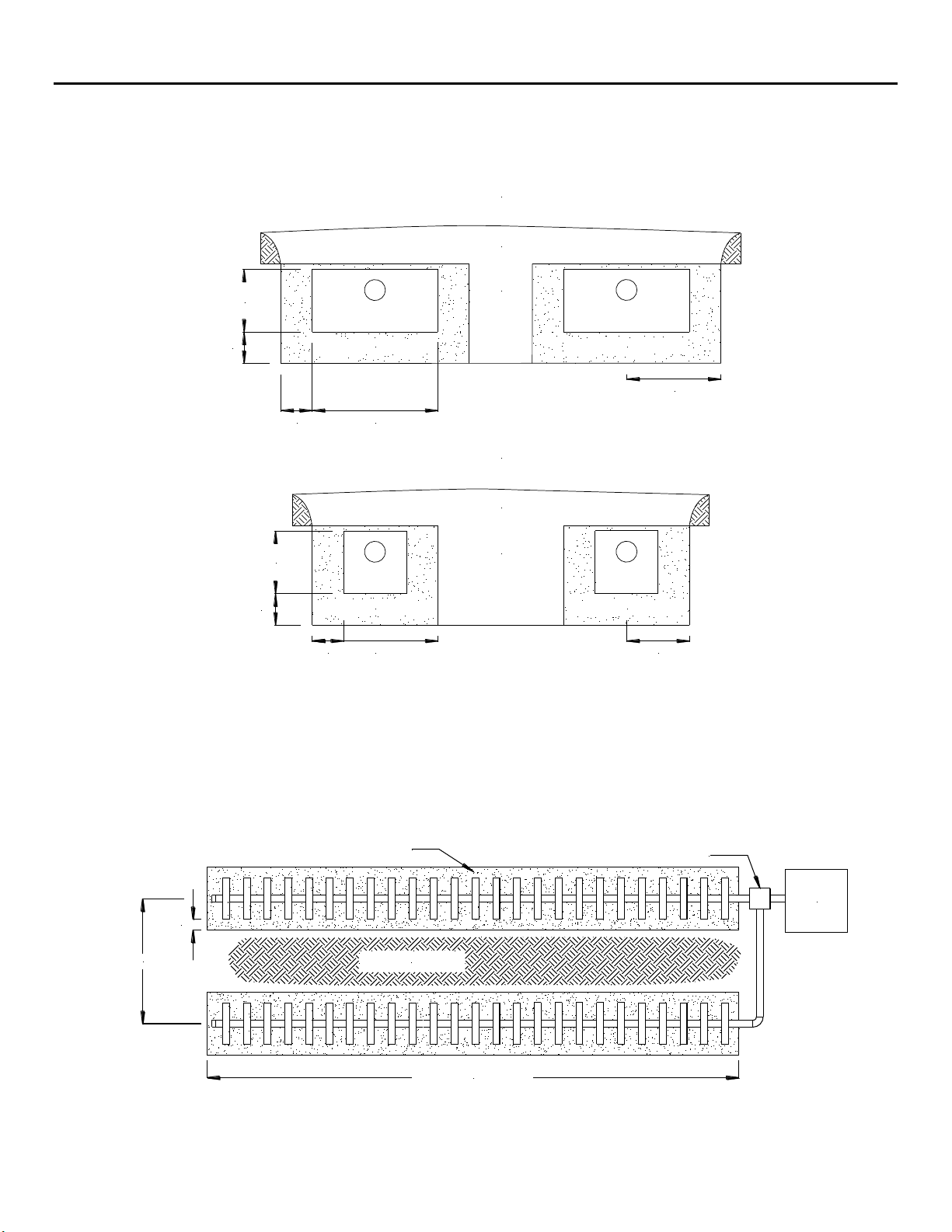
8.0 System Ventilation Example Drawing
FIGURE 12:MANTIS M5SERIES 2” BY-PASS LINE
OR SEPTIC TANK
PUMP CHAMBER
PER DESIGN
PER DESIGN
SPECIFIED SAND
6"
2" BY-PASS AIR LINE
FIGURE 13:MANTIS M5SERIES 2” BY-PASS LINE, CLOSE UP
SEPTIC
TANK
PUMP
TANK
MIN 2" DIABY-
PASSAIR LINE
D-BOX
OUT TO SYSTEM
Other manuals for Mantis M5 Series
2
Table of contents
Other Eljen Water Filtration System manuals


Popular Water Filtration System manuals by other brands

Water Factory Systems
Water Factory Systems SteamerGard WT-400 Use and care instructions, installation

Rewatec
Rewatec Prefilter Maxi Assembly instructions and mounting guide

OptiPure
OptiPure ScaleX2 SX2-11 Installation, operation & maintenance manual

GLOW
GLOW UV400 User's manual & installation instructions

Trox Technik
Trox Technik PFC Installation and maintenance manual

Nimbus Water Systems
Nimbus Water Systems Cascade NS-14 Owner's manual and installation guide


