BANDELIN Sonorex Technik User manual

23656a GB/2019-06
valid for:
Filtration FA 16 and FA 40 with filter aggregate FA 610
Filtration FA 75, FA 110, FA 180, FA 210, FA 220 and FA 320 with filter aggregate FA 620
3 4
Filtration FA
Operating Manual
Translation of Operating Manual

2 / 24 23656a GB/2019-06
1electronic GmbH & Co. KG • Heinrichstraße 3-4 • 12207 Berlin • Deutschland • [email protected]
Copyright & Disclaimer
This document may not be reproduced, either in full or in extracts, without prior approval of BANDELIN electronic GmbH & Co. KG,
hereinafter referred to as BANDELIN.
The German-language original is the binding version of this document. Any differences in the translation are not binding and have
no legal effect. In case of any discrepancies between the translation and the original of this document, the original version will take
precedence.
BANDELIN accepts no responsibility or liability for damage caused by improper handling or usage contrary to the intended purpose.
The documentation has been prepared with great care. All liability is excluded for any direct or indirect losses resulting from
incomplete or erroneous information contained in this documentation, or in its presentation or usage.
All images are provided as examples and are not true to size. Decorative elements are not included in the scope of delivery.
© 2019
1 2 GmbH & Co. KG, Heinrichstraße 3 – 4, Germany, 12207 Berlin,

23656a GB/2019-06 3 / 24
1electronic GmbH & Co. KG • Heinrichstraße 3-4 • 12207 Berlin • Deutschland • [email protected]
General information
The device, the accessories and the preparations are to be used as stated in the
Operating Manual or product literature.
The Manual forms part of the scope of delivery and is to be stored in the vicinity of the
device for later reference. This also applies if the device changes possession.
Before the device is put into service, this Manual must be read carefully and completely
to familiarise the user with all of the device functions.
Follow warnings and safety instructions (Chapter 1.5) at all times while using the
device.
The manufacturer assumes no responsibility for safety or the proper functioning of the
device in the event of improper handling or a use other than the intended use. In the
event of unauthorised alterations/modifications, both the warranty claim and the CE
conformity will expire.
If service is required, please contact the authorised dealer or the manufacturer.
Symbols used:
Symbol Meaning Explanation
Danger
Used to mark information that, if not observed, could
constitute a risk to life and limb, especially as a result of
electric shock.
Caution
Used to mark information that must be observed and complied
with in order to avoid damage to the device or injury to the
user.
Important Identifies information that is important for implementation.
Note Used to mark explanatory information.
Instructions Identifies instructions that must be followed in the described
sequence.

4 / 24 23656a GB/2019-06
1electronic GmbH & Co. KG • Heinrichstraße 3-4 • 12207 Berlin • Deutschland • [email protected]
Table of Contents
1 Product description ......................................................................................................6
1.1 Mode of operation ........................................................................................................7
1.2 Intended purpose .........................................................................................................7
1.3 CE conformity ...............................................................................................................7
1.4 Technical data, general ................................................................................................8
1.5 Warnings and safety instructions ...............................................................................10
2 Preparation .................................................................................................................11
2.1 Scope of delivery ........................................................................................................11
2.2 Assembly / Installation ...............................................................................................11
2.2.1 Connecting the FA 16, FA 40 or FA 75 .......................................................................12
2.2.2 Connecting the FA 110, FA 180 or FA 210 .................................................................13
2.2.3 Connecting the FA 220 or FA 320 ..............................................................................14
2.3 Commissioning ...........................................................................................................15
3 Operation ...................................................................................................................15
3.1 User controls ..............................................................................................................15
3.2 Device signals ............................................................................................................15
4 Use .............................................................................................................................16
4.1 Instructions for use .....................................................................................................16
4.2 General use ................................................................................................................16
5 Maintenance and cleaning .........................................................................................17
5.1 Cleaning and care ......................................................................................................17
5.2 Storage .......................................................................................................................17

23656a GB/2019-06 5 / 24
1electronic GmbH & Co. KG • Heinrichstraße 3-4 • 12207 Berlin • Deutschland • [email protected]
6 Maintenance and repair .............................................................................................17
6.1 Maintenance.................................................................................................................17
6.2 Troubleshooting ..........................................................................................................18
6.2.1 Replacing fuses ..........................................................................................................19
6.3 Customer service .......................................................................................................19
6.3.1 Repairs and service ...................................................................................................19
6.3.2 Decontamination certificate ........................................................................................20
7 Consumable materials ...............................................................................................20
8 Decommissioning .......................................................................................................20
Informative annexes
Connecting the oil separator and filter aggregate to an ultrasonic bath
Appendix
Original operating manual horizontal centrifugal pumps with magnetic coupling

SONOREX TECHNIK FA 610 filter aggregate
2
4
7
8
9
6
5
3
1
910
Example connection set
6 / 24 23656a GB/2019-06
1electronic GmbH & Co. KG • Heinrichstraße 3-4 • 12207 Berlin • Deutschland • [email protected]
1 Product description
Filter aggregate, type SONOREX TECHNIK FA ... .
The exact type specification and serial number are found on the identification plate on
the back.
A filtration is comprised of a filter aggregate and a corresponding connection set.
The filter aggregate is available in two sizes (FA 610 and FA 620) depending on the
bath volume to be cleaned.
The corresponding connection sets are customised to fit the ultrasonic bath.
Filter aggregate product features:
• Handle (1)
• Control box (2) with user controls
• Ball valve (3)
• Pre-filter (4)
• Fine filter (5)
• Stainless steel stand (6)
• Centrifugal pump (7)
• De-airing screw (8)
• Pressure switch (9)
Control box product features:
• On button (9)
• Off button (10)

23656a GB/2019-06 7 / 24
1electronic GmbH & Co. KG • Heinrichstraße 3-4 • 12207 Berlin • Deutschland • [email protected]
1.1 Mode of operation
The electrically operated SONOREX TECHNIK filtration provides continuous filtration
of cleaning liquid in a connected ultrasonic bath in the SONOREX TECHNIK RM / TM
series. This keeps ultrasonic bath cleaning liquid usable for a much longer period.
The filtration contains a filter aggregate which is made up of two filters (pre- and fine
filter) and a magnetically coupled centrifugal pump on a stand.
The pre-filter serves to protect the pump, while the fine filter provides deep-bed
filtration.
1.2 Intended purpose
Existing SONOREX TECHNIK RM/TM ultrasonic baths do not require conversion
before being equipped with a filtration.
The filtration serves to filter aqueous cleaning agents in bath temperatures of up to 70
°C/1 with bath contents measuring at least 13L with preflooded filter aggregate.
The unit is operated from the front on the control box using push buttons.
SONOREX TECHNIK filtrations are designed to be free-standing units.
1.3 CE conformity
The filter aggregate satisfies the CE marking criteria of the following European Directives:
- “Low-Voltage Directive”
- “Electromagnetic Compatibility” Directive
- RoHS directive
in their currently valid versions.
A declaration of conformity can be requested from the manufacturer by providing the
serial number.
/1 The filter cartridges may be used at a maximum permitted temperature of 70 °C.

8 / 24 23656a GB/2019-06
1electronic GmbH & Co. KG • Heinrichstraße 3-4 • 12207 Berlin • Deutschland • [email protected]
1.4 Technical data, general
The filter aggregate is interference-free and CE-marked.
Safety: EN 61010-1;
EMC: EN 61326-1
Filter aggregates FA 610 and FA 620:
Stand, fittings: Stainless steel, brass, galvanically coated and PP
Hoses: Stainless steel-reinforced HDPE
Dimensions: 460 × 440 × 680 mm (L × W × H)
Weight: approx. 20 kg
Mains connection: 230 V~ 50 Hz, 0.25 kW
Main cable length 2 m
Max. current consumption: 1.76 A
Fuse: 1× T 2.5 A
Pre-filter:
Housing: PP
Filter cartridge: Nylon-weave tray insert atop a filter element, fineness of
filtration 350 μm (reusable)
Filter cartridge size: FA 610: 9 ¾”
FA 620: 20”
Fine filter:
Housing: PP
Filter cartridge: Single-use wound filter cartridge made of PP, integrally
wound, fineness of filtration 25 μm
Filter cartridge size: FA 610: 9 ¾”
FA 620: 20”
Pump:
Design: magnetically coupled centrifugal pump
Material: PP (fibreglass-reinforced), HD charcoal, ceramic,
Viton seals (FPM)
Operating temperature: max. 70 °C
Pressure: max. 1.0 bar
Output rate: 6 m³/h, H = 10 m
Protection class: IP 55
For additional information, see pump operating manual (appendix).
Connection:
Inlet: G ½
Outlet: G ½

Protective wire blocking
access to hazardous
parts Dust protection
Protected against
water jets from any
direction
23656a GB/2019-06 9 / 24
1electronic GmbH & Co. KG • Heinrichstraße 3-4 • 12207 Berlin • Deutschland • [email protected]
Connection set (APF ... ):
EPDM hoses,
Brass hose sockets, galvanically coated
Stainless steel return flow pipe
More detailed information on
the IP 55 protection class
pursuant to DIN EN 60529:
Ambient conditions pursuant to EN 61 010-1
Overvoltage category: II
Degree of contamination: 1
Permissible relative humidity up to 31 °C: 80%
Permissible relative humidity up to 40 °C: 50%
Permissible ambient temperature: 5 to 40 °C
Condensation not allowed.
For indoor operation only.

10 / 24 23656a GB/2019-06
1electronic GmbH & Co. KG • Heinrichstraße 3-4 • 12207 Berlin • Deutschland • [email protected]
1.5 Warnings and safety instructions
General
• In accordance with its intended use and this Operating Manual, the filter aggregate
must only be used together with a SONOREX TECHNIK RM/TM ultrasonic bath.
Accordingly, the safety instructions as stated in the operating manual for the
SONOREX TECHNIK RM/TM ultrasonic bath also apply.
• All safety instructions given in the pump operating manual (appendix) apply as well.
• Do not bring cleaning agents in contact with eyes or skin.
• Avoid ingesting or breathing in cleaning agents.
• Do not operate the filter aggregate without liquids!
• The filter aggregate is designed for use in liquid temperatures of up to 70 °C.
• Only operate the filter aggregate with aqueous cleaning agents.
Do not use any of the following liquids:
- combustible liquids, solvents (non-aqueous) and non-combustible liquids like
TRI, PER, methylene chloride and the like.
- aggressive cleaning agents such as acids and chemicals that (for example)
contain or separate chlorine ions, such as certain disinfectants, washing-up
liquids, household cleaners or saline solutions.
• Do not expose the filter aggregate to corrosive influences.
• Device damage resulting from the use of unsuitable cleaning chemicals will void the
warranty.
• Keep the filter aggregate and the stand clean and dry.
• Use only the connection material supplied.
• If the device changes ownership, make sure to provide the new owner with the
Operating Manual and safety instructions as well.
Operation and transport
• Place the filter aggregate upright on a solid, dry surface. Note the required ambient
conditions (Chapter 1.4).
• Only connect the filter aggregate to outlets with a grounded socket.
• Do not allow the unit to run unattended.
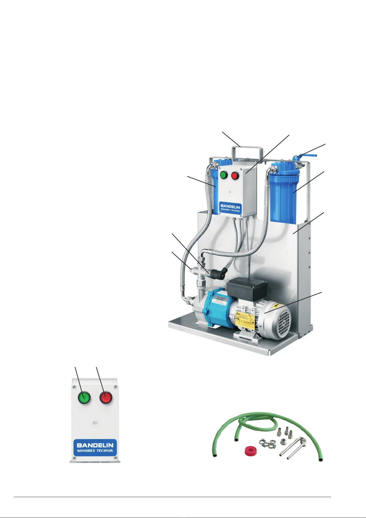
• The filter aggregate has a handle for transport purposes.
Damage and defects
• Disconnect the device from mains power immediately if defects are identified.
• Defective or damaged filter aggregates must only be serviced by the manufacturer
or by trained, authorised personnel.
• Always replace defective parts with SONOREX original parts or parts of the same
quality.
• Replace defective mains cables completely.

23656a GB/2019-06 11 / 24
1electronic GmbH & Co. KG • Heinrichstraße 3-4 • 12207 Berlin • Deutschland • [email protected]
2 Preparation
Carefully unpack the filter aggregate and accessories, and ensure that all parts are
present and have not been damaged in transit. Any identified damage or defects must
be communicated immediately to the responsible forwarding agent and the supplier in
writing.
Before operation, the filter aggregate should be allowed to stand for 2 hours at its
operating location so that it can adjust to the ambient conditions.
2.1 Scope of delivery
1 Filter aggregate, see delivery note
1 Connection set APF ...
1 Operating Manual
Additional accessories as ordered – see delivery note
The specific filter aggregate and connection set supplied depends on the tank contents
to be filtered and the size of the RM / TM ultrasonic bath being connected:
Type Filter aggregate Connection set
FA 16 FA 610 APF 16
FA 40 FA 610 APF 40/75
FA 75 FA 620 APF 40/75
FA 110 FA 620 APF 110/180/210
FA 180 FA 620 APF 110/180/210
FA 210 FA 620 APF 110/180/210
FA 220 FA 620 APF 220
FA 320 FA 620 APF 320
2.2 Assembly / Installation
The filter aggregate pump must be below the liquid level in the connected ultrasonic bath.
See the following pages for connection information.

12 / 24 23656a GB/2019-06
1electronic GmbH & Co. KG • Heinrichstraße 3-4 • 12207 Berlin • Deutschland • [email protected]
2.2.1 Connecting the FA 16, FA 40 or FA 75
Connecting the tank drain with the suction side of the filter aggregate:
1. Before assembly, wrap all external threads with several layers of Teflon tape.
2. FA 16: Screw the hose socket to the three-way ball valve (accessory pack RM 16).
FA 40/75: Screw the G ¾ – G ½ reducer and the hose socket to the three-way ball
valve.
3. Slide the hose ends onto the hose sockets and secure using hose clamps.
Connecting the tank inlet with the pressure side of the filter aggregate:
1. Screw the hose socket to the fine filter ball valve.
2. Slide the hose ends onto the hose sockets (return flow and fine filter) and secure
using hose clamps.
3. Insert the return flow hose into the bath nearby the overflow gutter (short side or
long side at the rear) and secure using 2 clamping screws.
Important:
When a filtration (FA) is being connected to an ultrasonic bath (RM 16 - 75) along with
an oil separator (OX), note that they can only be operated in alternation - see appendix.
Pre-filter
Ball valve
Fine filter
Information on flow direc-
tion within hose.
Filter aggregate
Return flow hose,
clamped to the tank
edge
Three-way ball
valve
Ultrasonic bath RM 16 to 75

23656a GB/2019-06 13 / 24
1electronic GmbH & Co. KG • Heinrichstraße 3-4 • 12207 Berlin • Deutschland • [email protected]
2.2.2 Connecting the FA 110, FA 180 or FA 210
Connecting the tank drain with the suction side of the filter aggregate:
1. Before assembly, wrap all external threads with several layers of Teflon tape.
2. Screw the G 1 – G ½ reducer and the hose socket to the three-way ball valve.
3. Slide the hose ends onto the hose sockets and secure using hose clamps.
Connecting the tank inlet with the pressure side of the filter aggregate:
1. Screw the hose socket to the fine filter ball valve.
2. Slide the hose ends onto the hose sockets (return flow and fine filter) and secure
using hose clamps.
3. Insert the return flow hose into the bath nearby the overflow gutter (short side or
long side at the rear) and secure using 2 clamping screws.
Return flow hose,
clamped to the tank
edge
Sprinkle tube
Three-way ball
valve
Ultrasonic bath
RM 110 to 210
RM / TM 112 to 212
Information on flow direc-
tion within hose.
Filter aggregate
Ball valve, without oil separator
(remove overflow gutter)
Pre-filter
Ball valve
Fine filter

14 / 24 23656a GB/2019-06
1electronic GmbH & Co. KG • Heinrichstraße 3-4 • 12207 Berlin • Deutschland • [email protected]
2.2.3 Connecting the FA 220 or FA 320
Connecting the tank drain with the suction side of the filter aggregate:
1. Before assembly, wrap all external threads with several layers of Teflon tape.
2. Replace the ball valve on the corresponding chamber for the three-way ball valve.
3. Screw the G 1 – G ½ reducer and the hose socket to the three-way ball valve.
4. Slide the hose ends onto the hose sockets and secure using hose clamps.
Connecting the tank inlet with the pressure side of the filter aggregate:
1. Screw the hose socket to the fine filter ball valve.
2. Slide the hose ends onto the hose sockets (return flow and fine filter) and secure
using hose clamps.
3. Insert the return flow hose into the tank on the opposite short side of the bath and
secure using 2 clamping screws.
Note:
It is not possible to connect an oil separator to the L 220 or the L 320.
Information on flow direc-
tion within hose.
Filter aggregate
Return flow hose,
clamped to the tank
edge
Three-way ball
valve
Ultrasonic bath
L 220 or 320
Pre-filter
Ball valve
Fine filter

1 On button (green)
2 Off button (red)
12
23656a GB/2019-06 15 / 24
1electronic GmbH & Co. KG • Heinrichstraße 3-4 • 12207 Berlin • Deutschland • [email protected]
2.3 Commissioning
Insert filter cartridges into the filter housings for the pre- and fine filters / check
whether filter cartridges have already been inserted.
Connect the filter aggregate to the ultrasonic bath, see Chapter 2.2.
Open the 3-way ball valve on the ultrasonic bath.
Open the ball valve on the filter aggregate all the way.
Fill the ultrasonic bath with liquid until the liquid level in the bath is above the
overflow gutter.
De-air the filter aggregate using the de-airing screw, and then reconnect.
Press the On button (green) on the control box to start the filter aggregate.
The green indicator light is continuously illuminated during operation.
Check the fill level in the ultrasonic bath multiple times and refill if necessary.
Make sure that liquid is continuously flowing into the ultrasonic bath.
Do not operate the pump without liquid!
3 Operation
3.1 User controls
The device is operated from the front:
• Press the On button (green) to start the filter
aggregate. The green indicator light is continuously
illuminated during operation.
• Press the Off button (red) to switch the filter
aggregate off.
• Use the ball valve to adjust the flow-through rate.
Note
The filtration can remain connected to mains power while
switched off. It can be disconnected from the mains by
pulling the mains plug out.
3.2 Device signals
The red Off button is also coupled to a pressure switch.
If it illuminates during operation, the fine filter cartridge is blocked and
needs to be replaced.
See Chapter 5.1.

16 / 24 23656a GB/2019-06
1electronic GmbH & Co. KG • Heinrichstraße 3-4 • 12207 Berlin • Deutschland • [email protected]
4 Use
4.1 Instructions for use
Check hose connections
• Check all hose connections between the filter aggregate and the ultrasonic bath for
leaks, especially after a longer period of non-use.
• The liquid must not exceed the maximum temperature of 70 °C.
Caution!
Sediment particles can build up within the pre-filter, filling and blocking the filter
housing completely, resulting in dry runs that can damage the pump. The pressure
switch (on the fine filter) does not monitor clogging of the pre-filter.
4.2 General use
Step 1: Preparation
Open the 3-way ball valve on the connected ultrasonic bath.
Open the ball valve on the filter aggregate.
Step 2: Switching on
Press the On button (green) to switch on the filter aggregate.
Use the ball valve on the filter aggregate to set the desired flow-through rate.
Note:
Reducing return flow speed can eliminate any whistling noises in the ultrasonic bath.
Step 3: Switching off the filter aggregate
If the cleaning tank is soiled with particles that tend toward sedimentation, make sure to
rinse with fresh cleaning agent before switching off the filter aggregate.
Failure to do so can result in pump damage.
Press the Off button (red) to switch off the filter aggregate.
For safety reasons, if the filter aggregate is to remain switched off for a longer
period, close the 3-way ball valve on the connected ultrasonic bath.

23656a GB/2019-06 17 / 24
1electronic GmbH & Co. KG • Heinrichstraße 3-4 • 12207 Berlin • Deutschland • [email protected]
5 Maintenance and cleaning
Regular cleaning and care of the filter aggregate will ensure an optimum lifespan.
CAUTION!
Disconnect the filter aggregate from mains power each time before cleaning or care.
Do not hose down and do not expose to splashed water.
No guarantee is provided for damage caused by the use of unsuitable disinfection
agents or detergents.
5.1 Cleaning and care
• Use only commercially available care products without scouring additives - do not
use abrasive cleaners.
• Wipe down using only a moist cloth and then allow to dry or wipe dry.
5.2 Storage
If not used for longer periods of time, empty the filter aggregate completely and store it
covered in a cool, dry place.
6 Maintenance and repair
6.1 Maintenance
• Keep the filter aggregate clean and dry.
• Replace used cleaning agents in the ultrasonic bath and the filter aggregate - do not
refresh by topping up.
• Filter cartridges must be replaced regularly - at the latest when the pressure switch
switches off.
The frequency with which the filter will need to be changed depends largely on the
type and degree of cleaning tank soiling.
Filter replacement:
Close the 3-way ball valve on the ultrasonic bath before replacing the filter, as
otherwise it will be running dry.
Pre-filter: Remove, clean/rinse or replace, depending on the degree of soiling. Rinse
the filter housing out thoroughly before replacing or re-inserting the filter
cartridge.

18 / 24 23656a GB/2019-06
1electronic GmbH & Co. KG • Heinrichstraße 3-4 • 12207 Berlin • Deutschland • [email protected]
Fine filter: If the pressure in the filter housing is too high, the pressure switch will
switch the pump off, and the red indicator light on the Off button will
illuminate.
Replace the filter cartridge.
Rinse the filter housing out thoroughly before replacing the filter cartridge.
After inserting a new filter cartridge and opening the three-way ball valve, check the
liquid level in the ultrasonic bath and fill if necessary.
This is particularly true for small cleaning tanks = small bath volume.
The filter aggregate can then be started again using the green On button - the red
indicator light will switch off.
6.2 Troubleshooting
SONOREX TECHNIK filter aggregates are robust constructions designed to offer
maximum reliability.
Nevertheless, the possibility of a malfunction due to a defective component can never
be ruled out entirely.
Caution!
Repairs must only be performed by authorised, qualified personnel!
Unauthorised repairs will void the warranty!
Seq.
no.:
Malfunction Possible cause(s)
1 Filter aggregate switches off, red
indicator light illuminates.
– Fine filter clogged
– Return flow throttled too far
– Return flow blocked, kinked or pinched
2 Filter aggregate switches off, red
indicator light does not illuminate.
– Mains power failure
– Defective fuse
3 Filter aggregate is running,
bubbles in inlet, little or no flow
volume in return flow.
– Bath drain closed
– Inlet blocked, improperly sealed, kinked
or pinched
– Pre-filter clogged
4 Filter aggregate running, hoses
filled but no flow volume
– Pump blocked, magnetic coupling
slipping

23656a GB/2019-06 19 / 24
1electronic GmbH & Co. KG • Heinrichstraße 3-4 • 12207 Berlin • Deutschland • [email protected]
6.2.1 Replacing fuses
Caution!
Repair work may only be carried out by authorised, qualified personnel or by the
manufacturer. The manufacturer assumes no liability for unauthorised work on the
device!
Danger!
Always isolate from mains power before opening!
Risk of electric shock from live parts in the control box!
• Disconnect the filter aggregate from mains power. Close the ball valves (ultrasonic
bath and filter aggregate).
• Remove the screws in the control box and open carefully.
• The fuse is inside the locking clip.
• Following inspection, replace only the defective fuse. The fuse rating is listed under
Technical Data, see Chapter 1.4.
• Reassemble the control box by following the above instructions in reverse.
• Reconnect the power cable. Re-open the ball valves.
6.3 Customer service
If service is required, please contact your specialist dealer or BANDELIN electronic to
order spare parts or before sending in the defective filter aggregate.
6.3.1 Repairs and service
If faults or defects have been discovered and cannot be rectified, stop using the filter
aggregate immediately. If this occurs, please contact the supplier or the manufacturer:
BANDELIN electronic GmbH & Co. KG
Heinrichstraße 3-4
12207 Berlin
Repair service: Email:
Fax: +49 30 768 802 00 13
Returns are subject to the General Conditions of Delivery and Payment of
BANDELIN electronic GmbH & Co. KG.
In addition, the filter aggregate must be cleaned and decontaminated as described in
the next chapter.

6.3.2 Decontamination certificate
If the filter aggregate is sent back to the manufacturer for repairs (with accessories, if
applicable), complete the "Certificate of Decontamination" form and affix it in a clearly
visible spot on the outside of the packaging.
If this form has not been filled out, we reserve the right to refuse receipt of the package
in order to protect our employees.
The form can be downloaded from our website as a PDF file:
www.bandelin.com - Downloads ...
7 Consumable materials
Filter cartridges:
Type Description Order No.
EF 1025 10 fine filter, 9 ¾", 25 μm 238
EF 2025 10 fine filter 20", 25 μm 8585
8 Decommissioning
If the filter aggregate is no longer functional, it must be disposed of
appropriately. Some components are considered hazardous waste.
BANDELIN electronic GmbH & Co. KG
Heinrichstraße 3 – 4
12207 Berlin
Deutschland
www.bandelin.com
+49 30 768 80-0
+49 30 773 46 99
Zertifiziert nach
ISO 9001
ISO 13485
Table of contents