WIL-17100-E-03 17
CSA-Certified Pumps
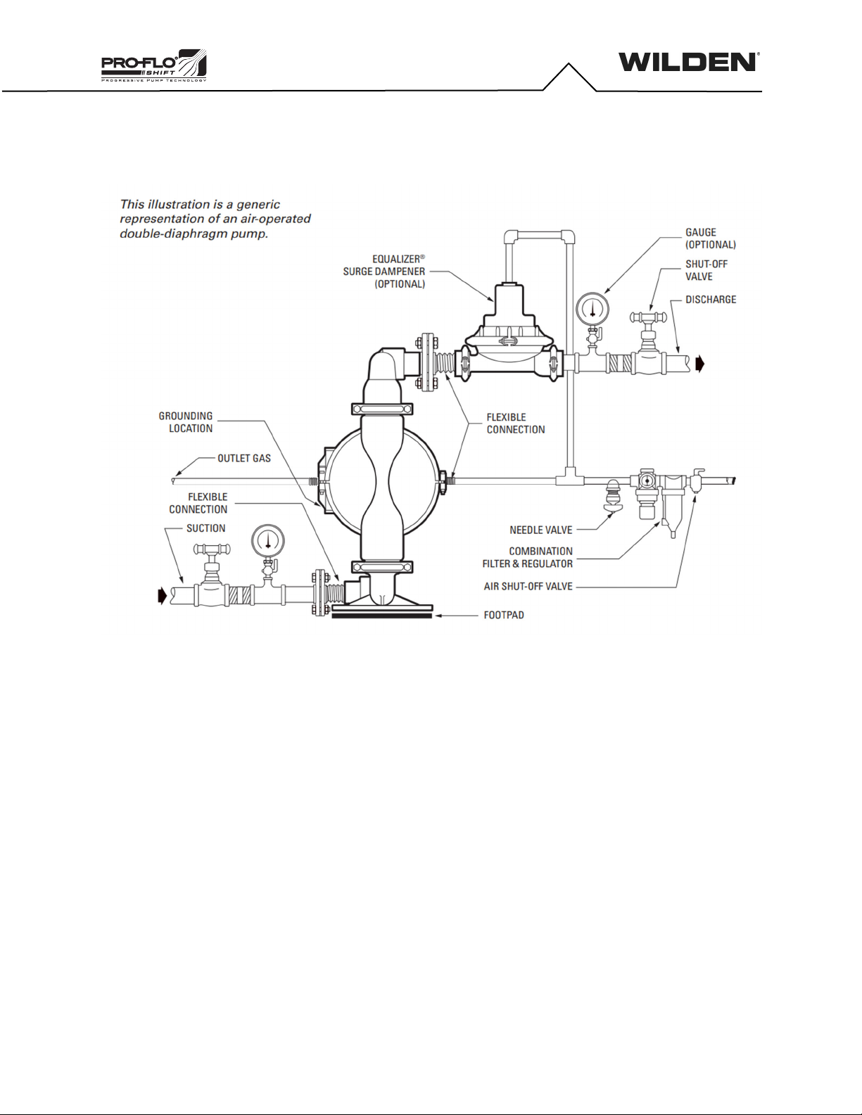
SECTION 6
Prior to pump installation, ensure that the flow and suction lift
requirements are within the pump model’s capabilities. Refer to the
Section 5, Performance of the Engineering, Operation and Maintenance
(EOM) Manual for specific flow and suction-lift capabilities.
Before installation confirm that the pump materials of construction are
compatible with pumping application. Refer to the Wilden Chemical
Resistance Guide for assistance with wetted path and elastomer options.
Piping
The pump should be located so that the length and complexity of the
suction and discharge piping is minimized. Unnecessary elbows, bends
and fittings can increase friction losses and should be avoided.
Pipe sizes should be selected to keep friction losses within practical limits.
The suction pipe diameter should be equivalent or larger than the
diameter of the suction inlet on your Wilden pump. The suction hose must
be non-collapsible, reinforced type as these pumps are capable of pulling
a high vacuum. Discharge piping should also be the equivalent or larger
than the diameter of the pump discharge to help reduce friction losses.
All piping should be supported independently of the pump. In addition, the
piping should be correctly aligned with the inlet and discharge connection
of the pump to avoid placing stress on the pump fittings. Flexible hose can
be installed to aid in absorbing the forces created by the natural
reciprocating action of the pump and will also assist in minimizing pump
vibration.
Gas Supply
The pump should have a supply line large enough (a 3/4” supply line is
recommended for 1-1/2” and larger pumps) to supply the volume of air
necessary to achieve the desired pumping rate. Gas pressure to the pump
should be controlled by a pressure-regulating valve and should not
exceed a maximum of 6.9 bar (100 psig). It is suggested that a needle
valve be placed in the supply line to control the flow of gas to the pump.
For best results, a 5μ(micron) filter should be installed before the gas inlet
of the pump to eliminate the majority of compressed gas line
contaminants.
Type of Gas
Sweet gas is required for natural gaspowered pumps. Please consult the
factory if considering using sour gas as levels of hydrogen sulfide (H2S)
may cause unacceptable corrosion and chemical attack.
Pump Mounting and Installation
For simple installation and removal of the pump shut-off valves should be
installed in the inlet and discharge plumbing. If the pump is to be mounted
in a fixed location, a mounting pad placed between the pump and the
foundation will assist in minimizing pump vibration. If quick-closing valves
are installed at any point in the discharge system, or if pulsation within a
system becomes a problem, a surge suppressor should be installed to
protect the pump, piping and gauges from surges and water hammer.
Solids Passage
All Wilden pumps are capable of passing solids. A strainer should be used
at the inlet of the pump to ensure that the pump’s rated solids capabilities
are not exceeded. Refer to the Section 5 of this EOM manual for specific
solids-passage capabilities.
Flooded Suction
Pumps in service with a positive suction head are most efficient when the
inlet pressure is limited to 0.5–0.7 bar (7–10 psig). Premature diaphragm
failure may occur if positive suction is 0.7 bar (10 psig) or higher.
Suction Lift
When used in self-priming applications, it is critical that all fittings and
connections are airtight, or a reduction or loss of pump suction capability
will result.
Gas Outlet
All CSA-certified pumps are fitted with the single point exhaust option so
that all exhaust gases are routed through the muffler plate exhaust port.
The gas outlet must be recaptured or vented to a safe location in
accordance with locally, nationally and/or industry recognized codes.
Grounding
Pumps and accessories must be electrically grounded to a proper
grounding point to prevent an accumulation of electro-static charge when
used in potentially explosive areas. CSA-certified pumps come with a
grounding strap and are fitted with a grounding screw for the purpose of
electrically grounding the pump. Periodic inspection of the ground
connection should be performed to ensure the equipment is properly
grounded. Refer to the Wilden CE Safety Supplement and Safety Manual
for additional ATEX-certified pump considerations.
Functional Testing
1. Tighten all hardware prior to initial start-up. Refer to Section 7,
Reassembly Hints & Tips in the EOM manual for torque
specifications.
2. Prior to pump installation connect compressed gas line [do not
exceed rated pressure of 6.9 bar (100 psig)] to gas inlet of pump to
ensure that pump cycles consistently.
3. Cycle pump for 2-3 minutes.
4. After pump installation, check piping connections for leaks.
Pump Operation
1. To avoid damage to the pump new installations should be checked
for any debris in tank or piping system.
2. Once installation is complete, pump operation can be started.
Confirm the shut-off valves in the inlet and discharge plumbing are
open. Do not exceed the pump’s maximum rated pressure of 6.9
bar (100 psig). A pressure regulating valve and needle valve can be
used to adjust the speed of the pump.
3. Retighten all exposed fasteners after two (2) hours of operation.
Refer to Section 7, Reassembly Hints & Tips in the EOM manual for
torque specifications.
Emergency Shut-Down Procedure
In the case of an emergency situation, the pump should be stopped
immediately. To stop the pump’s operation, close the gas shut–off valve
(user-supplied). A properly functioning valve will cut-off the gas supply,
stopping the pump. The shut-off valve should be located far enough away
from the pumping equipment such that it can be reached safely in an
emergency situation. In the event of pump or diaphragm failure, close
shut-off valves at the inlet and discharge of pump to eliminate the
possibility of medium leakage. In the event of a power failure, the gas
shut-off valve should be closed, if restarting of the pump is not desirable
once power is regained.
Refer to the Wilden CE Safety Supplement, Safety Manual and EOM
Manual for additional information.
SUGGESTED INSTALLATION, OPERATION, MAINTENANCE
AND TROUBLESHOOTING