manuals.online logo
Brands
  1. Home
  2. •
  3. Brands
  4. •
  5. webtrol
  6. •
  7. Water Pump
  8. •
  9. webtrol EZ Series Operating instructions

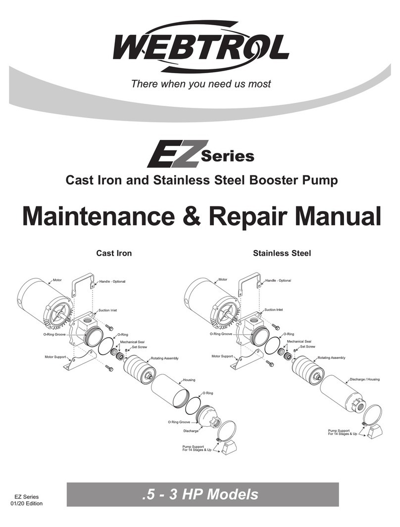
webtrol EZ Series Operating instructions

O-Ring Groove
Pump Support
For 14 Stages & Up
Motor
Grease Fitting
Water Slinger
Suction Inlet
O-Ring
Rotating Assembly
Set Screw
Set Screw
Gasket
Key
Discharge / Pump
Housing
Mechanical Seal
O-Ring Groove
O Ring Groove
Suction Inlet
O Ring
Discharge
Pump Housing
Pump Support
For 14 Stages & Up
Motor
Grease Fitting
Water Slinger
O-Ring
Rotating Assembly
Set Screw
Set Screw
Gasket
Key
Mechanical Seal
Stainless SteelCast Iron
Maintenance & Repair Manual
Cast Iron and Stainless Steel Booster Pump
EZ Series
01/20 Edition
5 HP Models
Installation of Rotating Assembly (RA)
Removal of Rotating Assembly (RA)
- 2 -
The following information applies to both cast iron
and stainless steel 5 HP models.
Procee as follows:
1. Loosen set screws in pump shaft coupling.
2. Date co e: 7-93 to present -
Cast iron - rotate discharge clockwise (left hand
threads) while holding pump housing with a strap
wrench. Then, remove the pump housing by rotating
it clockwise with a strap wrench.
Stainless steel - rotate welded discharge/pump
housing clockwise (left hand threads) with a strap
wrench.
Date co e: Prior to 7/93 - Rotate discharge counter -
clockwise (right hand threads).
3. Remove the top diffuser containing the brass or
rulon (maroon) bearing. The top impeller will be
exposed.
4. Grasp the SS shaft sleeve bearing and pull RA
away from the motor. (Care should be taken not to
damage the SS shaft sleeve bearing). If a pair of pli-
ers is needed to grasp the bearing, use some kind of
protective covering around the bearing. On longer
stage pumps, it might be necessary to squirt 3-in-1 oil
into the hole used for the set screw in the pump shaft
coupling - if this is done allow the oil to set overnight.
Then, insert a screwdriver into the suction inlet hole
and pry the pump shaft coupling off the motor shaft:
Warning: Always disconnect the electrical supply
prior to servicing the pump.
Note: If improperly installed, a 1/8” gap will exist
between the bottom plate and diffuser.
at the same time, pull the RA away from the motor.
You may have to apply a back and forth motion to
loosen the coupling from the motor shaft.
1. A) Cast iron mo els - Slide a new o-ring over the
threads on the suction inlet and discharge. Position
it in the groove up against the shoulder and
lubricate the o-ring with a FDA approved lubricant.
Lubricate the threads on the suction inlet and
discharge with Anti-Seize Lubricating Compound
(Part # 41003) or equivalent.
B) Stainless steel mo els - Repeat item 1.A for
the suction inlet.
2. Position the bottom plate of the rotating assembly
against the bottom diffuser. When properly installed,
you will be able to feel a raised hub and a 1/8” diame-
ter pin on the surface opposite the part number.
3. Position the coupling key in the keyway provided in
the motor shaft.
4. Align the keyway in the shaft coupling with the key
in the motor shaft and slide the pump shaft coupling
onto the motor shaft. (Do not tighten set screws in the
coupling at this time.)
5. Cast iron mo els, Rotate the pump housing
counter clockwise (left hand threads) onto the suction
inlet until the pump housing contacts the shoulder on
the suction inlet. Tighten with a strap wrench. Take
care not to pinch the o-ring.
Screw the discharge counter clockwise (left hand
threads) into the pump housing until the discharge
bottoms out against the pump housing. Take care not
to pinch the o-ring.
Stainless steel mo els - Rotate the discharge/pump
housing counter clockwise (left hand threads) onto
the suction inlet until the discharge/pump housing bot-
Motor
Motor
Pump
Housing
Pump
Housing
Discharge
2 Set Screws
Suction Inlet Discharge
Cast Iron Model
Stainless Steel Model
2 Set Screws
Suction Inlet
Bottom Plate
Bottom Diffuser
Pin
Rotating Assembly (RA)
O
Mechanical Seal Replacement
- 3 -
tom out against the suction inlet. Tighten with a
wrench. Take care not to pinch the o-ring.
Mechanical Seal Installation
1. Clean seal cavity, removing all rust and scale.
2. A) Lubricate the rubber seat ring with mineral oil.
With a 3/4” socket or piece of 3/4” PVC pipe, press
ceramic seat firmly and squarely into the seal
cavity. Be sure the seal face in not damaged during
assembly (cracked, scratched, or chipped) or the
seal will leak.
B) Clean polished surface of ceramic seat with a
soft cloth or tissue to remove all dust and grit.
C) Inspect motor shaft to make sure it is clean.
D) To prevent slip-stick lightly lubricate both the
ceramic and carbon seal face with mineral oil.
Do not let oil get on to the motor shaft or the
rubber driving ring of the mechanical seal.
E) For ease of assembly lubricate the driving ring
on the mechanical seal with water. By hand
carefully press the rotating seal assembly onto the
motor shaft. The carbon seal face must contact the
ceramic seal face. The driving ring must seal
against the motor shaft.
F) Place a 28B116-V gasket over the motor shaft
and against the rotating element of the mechanical
seal. Slide the 99X151-6 key in the keyway in the
motor shaft.
Suction Inlet
Pry Ceramic/Rubber Seat
Free Using A Screwdriver
Ceramic
Seat
Rubber
Seat
Ring
Seal
Cavity
Suction Inlet
Deep Socket o r
3/4" PVC Pipe
Rubber
Seat
Ring
Seal
Cavity
1. Follow instructions under “Removal of Rotating
Assembly.”
2. Remove the rotating element of the seal (carbon
ring, seal , and spring) by grasping the element and
pulling/twisting it off the motor shaft.
3. Use a screwdriver to remove the ceramic seat and
rubber seat ring from the seal cavity as shown. Be
careful not to damage sealing surfaces on the seal
cavity.
Rubber Driving Ring
3. To reassemble the rotating assembly refer to
Installation of Rotating Assembly (RA)
6. Seal the set screws in the coupling with pipe
sealant to prevent pumping liquid from contacting the
motor shaft. Before tightening the set screws in the
coupling, push on the cap screw located at the end of
the pump inside the discharge housing with a 7/16”
socket and extension. This will cause the motor shaft
to “Bottom Out” inside the pump shaft coupling. While
pushing on the cap screw, tighten the set screws in
the shaft coupling.
Motor
Allen Wrench
Apply Pressure To Extension
7/16" Socket
And Extension
1. Refer to “Removal of Rotating Assembly” (RA)
2. Refer to “Mechanical Seal Replacement”
instruction 2.
3. Remove the (4) 3/8” bolts that attach the suction
inlet to the motor.
4. Pull the suction inlet away from the motor.
5. Refer to “Mechanical Seal Installation”. and
“Installation Of Rotating Assembly” instructions 1-6.
1. After reassembly, rotate the pump shaft. It should
be free enough to be turned by hand. To do this,
insert a 7/16” socket into the discharge and rotate the
hex head cap screw clockwise.
2. If you can turn the shaft with minimum effort, the
booster pump is operable. If you cannot rotate the
pump shaft, check the following for improper installa-
tion.
A) The motor shaft must be bottomed out inside
the pump shaft coupling.
B) The bottom plate must be installed properly.
See Installation of Rotating Assembly, instruction 2.
C) The pump housing must be firmly tightened
against the shoulder of the suction inlet and
discharge.
1. Measure the length of the motor shaft from the
mounting surface of the motor to the shoulder of the
motor shaft that butts up against the pump shaft cou-
pling. This dimension should be 2.560 + .010.
2. Inspect shaft to make sure it is clean.
3. Slide the water slinger over the shaft, as far back
as possible.
4. Fasten, the suction inlet to the motor with (4)
3/8” x 1 1/4” bolts.
Installation of Motor
Final Inspection
2.560 + .010
NEMA 184 Frame
Motor
Rotating Assembly (RA)
2 Set Screws
Mechanical Seal Bottom Plate
Coupling
Gasket
Motor
Shaft
Pin
4 - 3/8" x 1 1/4" Bolts
Suction Inlet
Motor
Water Slinger
Removal of Motor
Motor Water Slinger
Warning: Always disconnect the electrical supply
prior to servicing the pump.
8417 ew Hampshire Ave. | St. Louis, MO 63123
Phone: (314) 631-9200 Fax: (314) 631-3738 E-mail: [email protected]

Other manuals for EZ Series

2

This manual suits for next models

1

Other webtrol Water Pump manuals

webtrol TC Series User manual

webtrol

webtrol TC Series User manual

webtrol WT Series Installation instructions

webtrol

webtrol WT Series Installation instructions

webtrol NV Series Installation instructions

webtrol

webtrol NV Series Installation instructions

webtrol PC Series Installation instructions

webtrol

webtrol PC Series Installation instructions

webtrol IN-LINE Series Installation instructions

webtrol

webtrol IN-LINE Series Installation instructions

webtrol VN50C49 Installation instructions
webtrol

webtrol VN50C49 Installation instructions

webtrol EZ Series Operating instructions

webtrol

webtrol EZ Series Operating instructions

webtrol WTE Series Installation instructions
webtrol

webtrol WTE Series Installation instructions

Popular Water Pump manuals by other brands

Harvest TEC 9214 owner's manual

Harvest TEC

Harvest TEC 9214 owner's manual

Edwards EXT200/200H ICPMS instruction manual

Edwards

Edwards EXT200/200H ICPMS instruction manual

Hydronic P825 Instructions for installation, use and maintenance manual

Hydronic

Hydronic P825 Instructions for installation, use and maintenance manual

Ceco Sethco P90S quick start guide

Ceco

Ceco Sethco P90S quick start guide

Schmalz EVE-TR 250 AC3-F operating instructions

Schmalz

Schmalz EVE-TR 250 AC3-F operating instructions

IWAKI AMERICA MDF-L Series instruction manual

IWAKI AMERICA

IWAKI AMERICA MDF-L Series instruction manual

GIANT PUMPS GP8035 Repair instructions

GIANT PUMPS

GIANT PUMPS GP8035 Repair instructions

Watson-Marlow MasoSine EC 25 manual

Watson-Marlow

Watson-Marlow MasoSine EC 25 manual

March Pumps 893-06 Safety Instructions & Preventive Maintenance

March Pumps

March Pumps 893-06 Safety Instructions & Preventive Maintenance

SprayTECH EP2510 owner's manual

SprayTECH

SprayTECH EP2510 owner's manual

Pentair Flotec E75STVT owner's manual

Pentair

Pentair Flotec E75STVT owner's manual

GORMAN-RUPP PUMPS PRIME AIRE PLUS PAH Series Installation, operation, and maintenance manual with parts list

GORMAN-RUPP PUMPS

GORMAN-RUPP PUMPS PRIME AIRE PLUS PAH Series Installation, operation, and maintenance manual with parts list

pumpa AD manual

pumpa

pumpa AD manual

GORMAN-RUPP PA Series Installation, operation and maintenance manual

GORMAN-RUPP

GORMAN-RUPP PA Series Installation, operation and maintenance manual

Danfoss 45 Frame K2 Series Service manual

Danfoss

Danfoss 45 Frame K2 Series Service manual

Varian TV 301 Navigator 969-8918 instruction manual

Varian

Varian TV 301 Navigator 969-8918 instruction manual

BUSCH COBRA NC 0630 instruction manual

BUSCH

BUSCH COBRA NC 0630 instruction manual

Gormann-Rupp Pumps 10 Series Installation, operation and maintenance manual

Gormann-Rupp Pumps

Gormann-Rupp Pumps 10 Series Installation, operation and maintenance manual

manuals.online logo
manuals.online logoBrands
  • About & Mission
  • Contact us
  • Privacy Policy
  • Terms and Conditions

Copyright 2025 Manuals.Online. All Rights Reserved.