EOM T1 Original Metal Series User manual

Simplify your process
Engineering
Operation &
Maintenance
Original™Series METAL Pumps
T1
WIL-10190-E-03
REPLACES WIL-10190-E-02
W
IL-10190-E-0
3
CS
C
l
a
s
s
I
&
I
I
O
z
o
n
e
D
e
p
l
e
t
i
n
g
S
u
b
s
t
a
n
c
e
s
NON
USE
U.S. Clean Air Act
Amendments of 1990
SECTION 1 CAUTIONS—READ FIRST! . . . . . . . . . . . . . . . . . . . . . . . . . . . . . . . . . . . . . . . . . . . . . .1
SECTION 2 WILDEN PUMP DESIGNATION SYSTEM. . . . . . . . . . . . . . . . . . . . . . . . . . . . . . . . .2
SECTION 3 HOW IT WORKS—PUMP & AIR DISTRIBUTION SYSTEM . . . . . . . . . . . . . . . .3
SECTION 4 DIMENSIONAL DRAWINGS . . . . . . . . . . . . . . . . . . . . . . . . . . . . . . . . . . . . . . . . . . . . .4
SECTION 5 PERFORMANCE
A. T1 Metal
Performance Curves
Rubber-Fitted . . . . . . . . . . . . . . . . . . . . . . . . . . . . . . . . . . . . . . . . . . . . . . . . . . . . . . . .5
TPE-Fitted . . . . . . . . . . . . . . . . . . . . . . . . . . . . . . . . . . . . . . . . . . . . . . . . . . . . . . . . . . .5
PTFE-Fitted . . . . . . . . . . . . . . . . . . . . . . . . . . . . . . . . . . . . . . . . . . . . . . . . . . . . . . . . . .6
B. Suction Lift Curves . . . . . . . . . . . . . . . . . . . . . . . . . . . . . . . . . . . . . . . . . . . . . . . . . . . . . .7
SECTION 6 SUGGESTED INSTALLATION, OPERATION & TROUBLESHOOTING. . . . . . . .8
SECTION 7 ASSEMBLY / DISASSEMBLY . . . . . . . . . . . . . . . . . . . . . . . . . . . . . . . . . . . . . . . . . . . 11
Air Valve/Center Section Repair/Maintenance . . . . . . . . . . . . . . . . . . . . . . . . . . . . . . . . .14
O-Ring Replacement/Center Section. . . . . . . . . . . . . . . . . . . . . . . . . . . . . . . . . . . . . . . . . 14
Reassembly Hints &Tips . . . . . . . . . . . . . . . . . . . . . . . . . . . . . . . . . . . . . . . . . . . . . . . . . . 15
SECTION 8 EXPLODED VIEW AND PARTS LISTING
T1 Metal Rubber/TPE-Fitted . . . . . . . . . . . . . . . . . . . . . . . . . . . . . . . . . . . . . . . . . . . . . . . .16
T1 Metal PTFE-Fitted . . . . . . . . . . . . . . . . . . . . . . . . . . . . . . . . . . . . . . . . . . . . . . . . . . . . .18
SECTION 9 ELASTOMER OPTIONS. . . . . . . . . . . . . . . . . . . . . . . . . . . . . . . . . . . . . . . . . . . . . . . . .20
TABLE OF CONTENTS

1WILDEN PUMP & ENGINEERING, LLCWIL-10190-E-03
TEMPERATURE LIMITS:
Nylon –17.8°C to 93.3°C 0°F to 200°F
Neoprene –17.8°C to 93.3°C 0°F to 200°F
Buna-N –12.2°C to 82.2°C 10°F to 180°F
EPDM –51.1°C to 137.8°C –60°F to 280°F
Viton®–40°C to 176.7°C –40°F to 350°F
Wil-Flex™ –40°C to 107.2°C –40°F to 225°F
Polyurethane 12.2°C to 65.6°C 10°F to 150°F
Saniflex™ –28.9°C to 104.4°C –20°F to 220°F
PTFE –28.9°C to 148.9°C –20°F to 300°F
CAUTION: When choosing pump materials, be sure
to check the temperature limits for all wetted compo-
nents. Example: Viton®has a maximum limit of 176.7°C
(350°F) but polypropylene has a maximum limit of only
79°C (175°F).
CAUTION: Maximum temperature limits are based
upon mechanical stress only. Certain chemicals will
significantly reduce maximum safe operating tempera-
tures. Consult engineering guide for chemical compat-
ibility and temperature limits.
CAUTION: Always wear safety glasses when operat-
ing pump. If diaphragm rupture occurs, material being
pumped may be forced out air exhaust.
WARNING: Prevention of static sparking — If static
sparking occurs, fire or explosion could result. Pump,
valves, and containers must be properly grounded when
handling flammable fluids and whenever discharge of
static electricity is a hazard.
CAUTION: Do not exceed 8.6 bar (125 psig) air supply
pressure.
CAUTION: Before any maintenance or repair is
attempted, the compressed air line to the pump should
be disconnected and all air pressure allowed to bleed
from pump. Disconnect all intake, discharge and air
lines. Drain the pump by turning it upside down and
allowing any fluid to flow into a suitable container.
CAUTION: Blow out air line for 10 to 20 seconds
before attaching to pump to make sure all pipe line
debris is clear. Use an in-line air filter. A 5μ(micron) air
filter is recommended.
NOTE: Tighten clamp bands and retainers prior to
installation. Fittings may loosen during transportation.
NOTE: When installing PTFE diaphragms, it is impor-
tant to tighten outer pistons simultaneously (turning in
opposite directions) to ensure tight fit.
NOTE: Before starting disassembly, mark a line from
each liquid chamber to its corresponding air chamber.
This line will assist in proper alignment during reas-
sembly.
CAUTION: Verify the chemical compatibility of the
process and cleaning fluid to the pump’s component
materials in the Chemical Resistance Guide (see E4).
CAUTION: When removing the end cap using
compressed air, the air valve end cap may come out
with considerable force. Hand protection such as a
padded glove or rag should be used to capture the
end cap.
NOTE: All non lube-free air-operated pumps must
be lubricated. Wilden suggests an arctic 5 weight oil
(ISO grade 15). Do not over-lubricate air supply. Over-
lubrication will reduce pump performance.
Section 1
CAUTIONS—READ FIRST!
2
WILDEN PUMP & ENGINEERING, LLC WIL-10190-E-03
Section 2
PUMP DESIGNATION SYSTEM
MODEL
T1 = 13 MM (1/2”)
WETTED PARTS & OUTER
PISTON
AA = ALUMINUM /
ALUMINUM
AZ = ALUMINUM / NO PISTON
CENTER SECTION
YY = NYLON
AIR VALVE
B = BRASS
DIAPHRAGMS
BNS = BUNA-N (Red Dot)
FSS = SANIFLEX™
[Hytrel®(Cream)]
PUS = POLYURETHANE (Clear)
THU = PTFE W/HIGH-TEMP
BUNA-N BACK-UP
(White)
TNL = PTFE W/NEOPRENE
BACK-UP O-RING,
IPD (White)
TNU = PTFE W/NEOPRENE
BACK-UP (White)
TSU = PTFE W/SANIFLEX™
BACK-UP (White)
VTS = VITON®(White Dot)
WFS = WIL-FLEX™ [Santoprene®
(Orange Dot)]
XBS = CONDUCTIVE BUNA-N
(Two Red Dots)
VALVE BALL
BN = BUNA-N (Red Dot)
FS = SANIFLEX™
[Hytrel® (Cream)]
PU = POLYURETHANE (Brown)
TF = PTFE (White)
VT = VITON®(White Dot)
WF = WIL-FLEX™ [Santoprene®
(Orange Dot)]
VALVE SEAT
A = ALUMINUM
H = ALLOY C
S = STAINLESS STEEL
VT = VITON® (White Dot)
VALVE SEAT O-RING
BN = BUNA-N
FS = SANIFLEX™
[Hytrel® (Cream)]
PU = POLYURETHANE (Brown)
TF = PTFE
WF = WIL-FLEX™ [Santoprene®]
T1 ORIGINAL™
METAL
13 mm (1/2") Pump
Maximum Flow Rate:
54.9 lpm (14.5 gpm)
SPECIALTY CODES
0014 BSPT
MATERIAL CODES
Viton®is a registered trademarks of DuPont Dow Elastomers.
LEGEND
T1 /XXXXX/ XXX / XX /XXX / XXXX
O-RINGS
MODEL VALVE SEAT
VALVE BALLS
DIAPHRAGMS
AIR VALVE
CENTER SECTION
WETTED PARTS & OUTER PISTON
SPECIALTY
CODE
(if applicable)
NOTE: MOST ELASTOMERIC MATERIALS USE COLORED DOTS FOR IDENTIFICATION.

3WILDEN PUMP & ENGINEERING, LLCWIL-10190-E-03
The Wilden diaphragm pump is an air-operated, positive displacement, self-priming pump. These drawings show the flow
pattern through the pump upon its initial stroke. It is assumed the pump has no fluid in it prior to its initial stroke.
FIGURE 1 The air valve directs pres-
surized air to the back side of diaphragm
A. The compressed air is applied directly
to the liquid column separated by elasto-
meric diaphragms. The diaphragm acts
as a separation membrane between the
compressed air and liquid, balancing the
load and removing mechanical stress
from the diaphragm. The compressed
air moves the diaphragm away from the
center block of the pump. The oppo-
site diaphragm is pulled in by the shaft
connected to the pressurized diaphragm.
Diaphragm B is on its suction stroke; air
behind the diaphragm has been forced
out to the atmosphere through the
exhaust port of the pump. The move-
ment of diaphragm B toward the center
block of the pump creates a vacuum
within chamber B. Atmospheric pressure
forces fluid into the inlet manifold forcing
the inlet valve ball off its seat. Liquid is
free to move past the inlet valve ball
and fill the liquid chamber (see shaded
area).
FIGURE 2 When the pressurized
diaphragm, diaphragm A, reaches the
limit of its discharge stroke, the air valve
redirects pressurized air to the back
side of diaphragm B. The pressurized
air forces diaphragm B away from the
center block while pulling diaphragm A
to the center block. Diaphragm B is now
on its discharge stroke. Diaphragm B
forces the inlet valve ball onto its seat
due to the hydraulic forces developed
in the liquid chamber and manifold of
the pump. These same hydraulic forces
lift the discharge valve ball off its seat,
while the opposite discharge valve ball is
forced onto its seat, forcing fluid to flow
through the pump discharge. The move-
ment of diaphragm A toward the center
block of the pump creates a vacuum
within liquid chamber A. Atmospheric
pressure forces fluid into the inlet mani-
fold of the pump. The inlet valve ball is
forced off its seat allowing the fluid being
pumped to fill the liquid chamber.
FIGURE 3 At completion of the stroke,
the air valve again redirects air to the
back side of diaphragm A, which starts
diaphragm B on its exhaust stroke. As
the pump reaches its original starting
point, each diaphragm has gone through
one exhaust and one discharge stroke.
This constitutes one complete pump-
ing cycle. The pump may take several
cycles to completely prime depending on
the conditions of the application.
RIGHT STROKE MID STROKE LEFT STROKE
Section 3
HOW IT WORKS—PUMP DISTRIBUTION SYSTEM

4
WILDEN PUMP & ENGINEERING, LLC WIL-10190-E-03
A
B
C
F
G
H
J
K L
P
13 mm
(1/2”) FNPT
LIQUID DISCHARGE
10 mm
(3/8”) FNPT
AIR EXHAUST
13 mm
(1/2”) FNPT
LIQUID INLET
6 mm
(1/4”) FNPT
AIR INLET
E - ALUM.
D - S.S.
M-ALUM.
N - S.S.
DIMENSIONS
ITEM METRIC (mm) STANDARD (inch)
A 28 1.1
B 117 4.6
C 198 7.8
D 203 8.0
E 208 8.2
F 224 8.8
G 175 6.9
H 140 5.5
J 112 4.4
K 84 3.3
L 102 4.0
M 30 1.2
N 30 1.2
P 8 0.3
BSP threads available for liquid inlet and discharge.
Section 4
DIMENSIONAL DRAWING
5WILDEN PUMP & ENGINEERING, LLCWIL-10190-E-03
Height ...................................224 mm (8.8")
Width ....................................208 mm (8.2")
Depth ....................................178 mm (7.0")
Est. Ship Weight ........
Aluminum 6 kg (13 lbs)
Stainless Steel 9 kg (20 lbs)
Air Inlet .................................... 6 mm (1/4")
Inlet........................................ 13 mm (1/2")
Outlet ..................................... 13 mm (1/2")
Suction Lift ..........................1.22 m Dry (4')
9.14 m Wet (30')
Displacement per
Stroke.........................0.06 l (0.017 gal.)1
Max. Flow Rate........... 54.9 lpm (14.5 gpm)
Max. Size Solids ................. 1.6 mm (1/16")
1Displacement per stroke was calculated at 4.8
bar (70 psig) air inlet pressure against a 2 bar
(30 psig) head pressure.
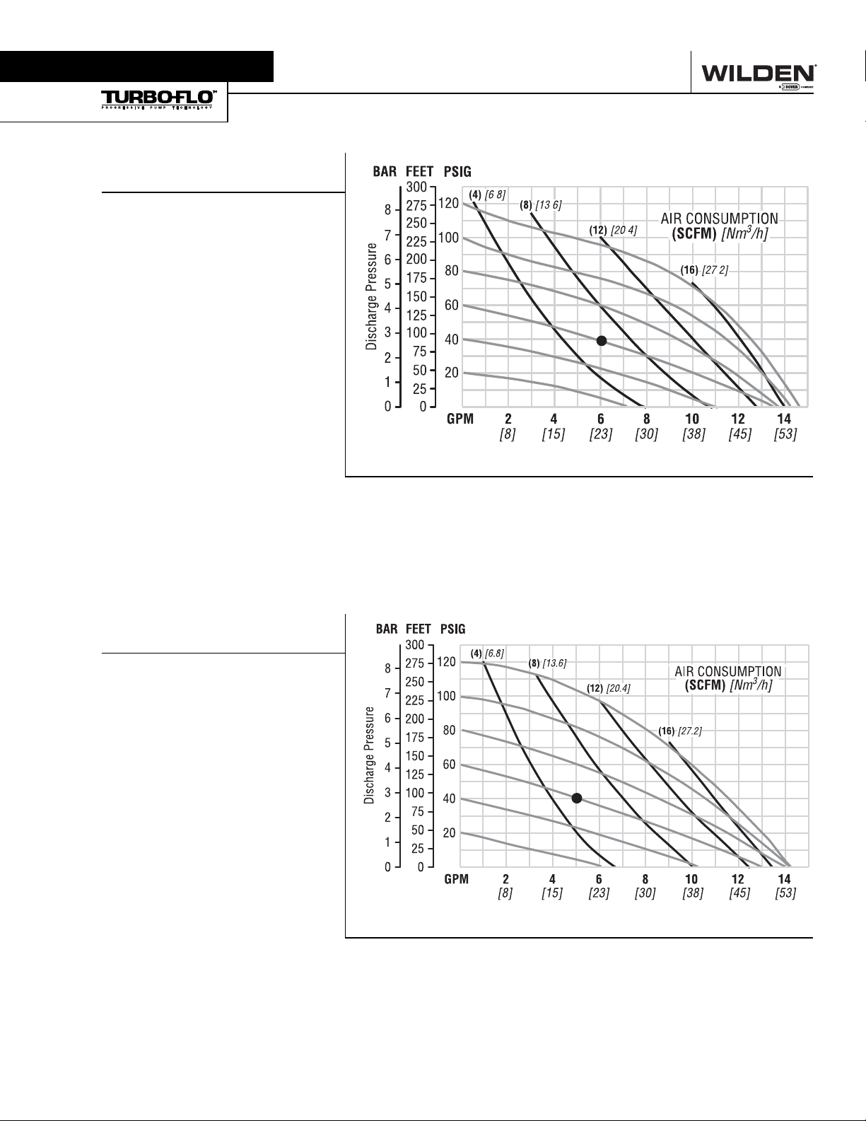
Example: To pump 22.7 lpm (6.0 gpm)
against a discharge pressure head of 2.7
bar (40 psig) requires 4 bar (60 psig) and
10.2 Nm3/h (6 scfm) air consumption. (See
dot on chart.)
Caution: Do not exceed 8.6 bar (125 psig) air
supply pressure.
Flow rates indicated on chart were determined by pumping water.
For optimum life and performance, pumps should be specified so that daily operation parameters
will fall in the center of the pump performance curve.
Height ...................................224 mm (8.8")
Width ....................................208 mm (8.2")
Depth ....................................178 mm (7.0")
Est. Ship Weight ........
Aluminum 6 kg (13 lbs)
Stainless Steel 9 kg (20 lbs)
Air Inlet .................................... 6 mm (1/4")
Inlet........................................ 13 mm (1/2")
Outlet ..................................... 13 mm (1/2")
Suction Lift ..........................1.52 m Dry (5')
9.45 m Wet (31')
Displacement per
Stroke.........................0.06 l (0.017 gal.)1
Max. Flow Rate........... 54.1 lpm (14.3 gpm)
Max. Size Solids ................. 1.6 mm (1/16")
1Displacement per stroke was calculated at 4.8
bar (70 psig) air inlet pressure against a 2 bar
(30 psig) head pressure.
Example: To pump 18.9 lpm (5.0 gpm)
against a discharge pressure head of 2.7
bar (40 psig) requires 4 bar (60 psig) and
8.5 Nm3/h (5 scfm) air consumption. (See
dot on chart.)
Caution: Do not exceed 8.6 bar (125 psig) air
supply pressure.
Flow rates indicated on chart were determined by pumping water.
For optimum life and performance, pumps should be specified so that daily operation parameters
will fall in the center of the pump performance curve.
Section 5A
PERFORMANCE
T1 METAL
RUBBER-FITTED
[LPM]
Water Discharge Flow Rates
T1 METAL
TPE -FITTED
[LPM]
Water Discharge Flow Rates

6
WILDEN PUMP & ENGINEERING, LLC WIL-10190-E-03
Height ...................................224 mm (8.8")
Width ....................................208 mm (8.2")
Depth ....................................178 mm (7.0")
Est. Ship Weight ........
Aluminum 6 kg (13 lbs)
Stainless Steel 9 kg (20 lbs)
Air Inlet .................................... 6 mm (1/4")
Inlet........................................ 13 mm (1/2")
Outlet ..................................... 13 mm (1/2")
Suction Lift ..........................2.74 m Dry (1')
9.14 m Wet (30')
Displacement per
Stroke.........................0.05 l (0.014 gal.)1
Max. Flow Rate........... 53.0 lpm (14.0 gpm)
Max. Size Solids ................. 1.6 mm (1/16")
1Displacement per stroke was calculated at 4.8
bar (70 psig) air inlet pressure against a 2 bar
(30 psig) head pressure.
Example: To pump 22.7 lpm (6 gpm) against
a discharge pressure head of 2 bar (30 psig)
requires 4 bar (60 psig) and 10.2 Nm3/h (6
scfm) air consumption. (See dot on chart.)
Caution: Do not exceed 8.6 bar (125 psig) air
supply pressure.
Flow rates indicated on chart were determined by pumping water.
For optimum life and performance, pumps should be specified so that daily operation parameters
will fall in the center of the pump performance curve.
T1 METAL
PTFE-FITTED
[LPM]
Water Discharge Flow Rates
Section 5A
PERFORMANCE
7WILDEN PUMP & ENGINEERING, LLCWIL-10190-E-03
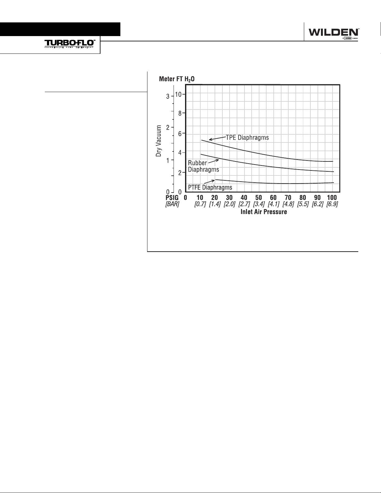
These vacuum numbers will double when a small amount
of back pressure is placed on the discharge.
T1 METAL SUCTION
LIFT CAPABILITY
Suction lift curves are calibrated for
pumps operating at 305 m (1,000’)
above sea level. This chart is meant
to be a guide only. There are many
variables which can affect your
pump’s operating characteristics.
The number of intake and discharge
elbows, viscosity of pumping fluid,
elevation (atmospheric pressure) and
pipe friction loss all affect the amount
of suction lift your pump will attain.
Section 5B
SUCTION LIFT CURVE

8
WILDEN PUMP & ENGINEERING, LLC WIL-10190-E-03
The Model T1 Metal pump has a 13 mm (1/2") inlet and
13 mm (1/2") outlet and is designed for flows to 54.9 lpm
(14.5 gpm). The T1 Metal pump is manufactured with wetted
parts of aluminum or stainless steel. The center section of the
T1 Metal pump is of nylon construction. The air distribution
system consists of a brass air valve body, aluminum air valve
piston, Buna-N o-rings and a bronze center section bushing.
A variety of diaphragms, valve balls, valve seats, and o-rings
are available to satisfy temperature, chemical compatibility,
abrasion and flex concerns.
The suction pipe size should be at least 13 mm (1/2") diam-
eter or larger if highly viscous material is being pumped. The
suction hose must be non-collapsible, reinforced type as the
T1 is capable of pulling a high vacuum. Discharge piping
should be at least 13 mm (1/2"); larger diameter can be
used to reduce friction losses. It is critical that all fittings and
connections are airtight or a reduction or loss of pump suction
capability will result.
INSTALLATION: Months of careful planning, study, and selec-
tion efforts can result in unsatisfactory pump performance if
installation details are left to chance.
Premature failure and long term dissatisfaction can be avoided
if reasonable care is exercised throughout the installation
process.
LOCATION: Noise, safety, and other logistical factors usually
dictate that “utility” equipment be situated away from the
production floor. Multiple installations with conflicting require-
ments can result in congestion of utility areas, leaving few
choices for siting of additional pumps.
Within the framework of these and other existing conditions,
every pump should be located in such a way that four key factors
are balanced against each other to maximum advantage.
1. ACCESS: First of all, the location should be accessible. If
it’s easy to reach the pump, maintenance personnel will have
an easier time carrying out routine inspections and adjust-
ments. Should major repairs become necessary, ease of
access can play a key role in speeding the repair process and
reducing total downtime.
2. AIR SUPPLY: Every pump location should have an air line
large enough to supply the volume of air necessary to achieve
the desired pumping rate (see pump performance chart). Use
air pressure up to a maximum of 8.6 bar (125 psig) depending
upon pumping requirements. The use of an air filter before the
pump will ensure that the majority of any pipeline contami-
nants will be eliminated. For best results, the pumps should
use an air filter, regulator, and lubricator system.
3. ELEVATION: Selecting a site that is well within the pump’s
suction lift capability will assure that loss-of-prime troubles will
be eliminated. In addition, pump efficiency can be adversely
affected if proper attention is not given to elevation (see pump
performance chart).
4. PIPING: Final determination of the pump site should not be
made until the piping problems of each possible location have
been evaluated. The impact of current and future installations
should be considered ahead of time to make sure that inadver-
tent restrictions are not created for any remaining sites.
The best choice possible will be a site involving the shortest
and the straightest hook-up of suction and discharge piping.
Unnecessary elbows, bends, and fittings should be avoided.
Pipe sizes should be selected so as to keep friction losses
within practical limits. All piping should be supported indepen-
dently of the pump. In addition, it should line up without plac-
ing stress on the pump fittings.
Expansion joints can be installed to aid in absorbing the forces
created by the natural reciprocating action of the pump. If the
pump is to be bolted down to a solid foundation, a mount-
ing pad placed between the pump and foundation will assist
in minimizing pump vibration. Flexible connections between
the pump and rigid piping will also assist in minimizing pump
vibration. If quick-closing valves are installed at any point in the
discharge system, or if pulsation within a system becomes a
problem, a surge suppressor should be installed to protect the
pump, piping and gauges from surges and water hammer.
When pumps are installed in applications involving flooded
suction or suction head pressures, a gate valve should be
installed in the suction line to permit closing of the line for
pump service.
The T1 can be used in submersible applications only when both
wetted and non-wetted portions are compatible with the mate-
rial being pumped. If the pump is to be used in a submersible
application, a hose should be attached to the pump’s air exhaust
and the exhaust air piped above the liquid level.
If the pump is to be used in a self-priming application, be sure
that all connections are airtight and that the suction lift is within
the pump’s ability. Note: Materials of construction and elasto-
mer material have an effect on suction lift parameters. Please
refer to pump performance data.
Pumps in service with a positive suction head are most effi-
cient when inlet pressure is limited to 0.5–0.7 bar (7–10 psig).
Premature diaphragm failure may occur if positive suction is
0.8 bar (11 psig) and higher.
THE MODEL T1 WILL PASS 1.6 mm (1/16") SOLIDS. WHEN-
EVER THE POSSIBILITY EXISTS THAT LARGER SOLID
OBJECTS MAY BE SUCKED INTO THE PUMP, A STRAINER
SHOULD BE USED ON THE SUCTION LINE.
CAUTION: DO NOT EXCEED 8.6 BAR (125 PSIG) AIR
SUPPLY PRESSURE.
BLOW OUT AIR LINE FOR 10 TO 20 SECONDS BEFORE
ATTACHING TO PUMP TO MAKE SURE ALL PIPE LINE
DEBRIS IS CLEAR. ALWAYS USE AN IN-LINE AIR
FILTER.
PUMPS SHOULD BE THOROUGHLY FLUSHED WITH
WATER BEFORE INSTALLING INTO PROCESS LINES.
FDA AND USDA PUMPS SHOULD BE CLEANED AND/OR
SANITIZED BEFORE USE ON EDIBLE PRODUCTS.
Section 6
SUGGESTED INSTALLATION

9WILDEN PUMP & ENGINEERING, LLCWIL-10190-E-03
OPERATION: Pump discharge rate can be controlled by
limiting the volume and/or pressure of the air supply to the
pump (preferred method). A regulator is used to regulate air
pressure. A needle valve is used to regulate air volume. Pump
discharge rate can also be controlled by throttling the pump
discharge by partially closing a valve in the discharge line of
the pump. This action increases friction loss which reduces
flow rate. This is useful when the need exists to control the
pump from a remote location. When the pump discharge
pressure equals or exceeds the air supply pressure, the
pump will stop; no bypass or pressure relief valve is needed,
and pump damage will not occur. The pump has reached a
“deadhead” situation and can be restarted by reducing the
fluid discharge pressure or increasing the air inlet pressure.
The Wilden T1 pump runs solely on compressed air and does
not generate heat, therefore your process fluid temperature
will not be affected.
RECORDS: When service is required, a record should be
made of all necessary repairs and replacements. Over a
period of time, such records can become a valuable tool for
predicting and preventing future maintenance problems and
unscheduled downtime. In addition, accurate records make
it possible to identify pumps that are poorly suited to their
applications.
MAINTENANCE AND INSPECTIONS: Since each applica-
tion is unique, maintenance schedules may be different for
every pump. Frequency of use, line pressure, viscosity and
abrasiveness of process fluid all affect the parts life of a
Wilden pump. Periodic inspections have been found to offer
the best means for preventing unscheduled pump downtime.
Personnel familiar with the pump’s construction and service
should be informed of any abnormalities that are detected
during operation.
NOTE: In the event of a power failure, the shutoff
valve should be closed, if the restarting of the pump
is not desirable once power is regained.
AIR OPERATED PUMPS: To stop the pump from
operating in an emergency situation, simply close the “shut-off” valve
(user supplied) installed in the air supply line. A properly functioning valve
will stop the air supply to the pump, therefore stopping output. This shut-
off valve should be located far enough away from the pumping equipment
such that it can be reached safely in an emergency situation.
®
Section 5A
SUGGESTED INSTALLATION
SUGGESTED OPERATION & MAINTENANCE

10
WILDEN PUMP & ENGINEERING, LLC WIL-10190-E-03
Pump will not run or runs slowly.
1. Check air inlet screen and air filter for debris.
2. Check for sticking air valve, flush air valve in solvent.
3. Check for worn out air valve. If piston face in air valve is
shiny instead of dull, air valve is probably worn beyond
working tolerances and must be replaced.
4. Check center block o-rings. If worn excessively, they will
not seal and air will simply flow through pump and out air
exhaust. Use only Wilden o-rings as they are of special
construction and ISO 15-5 wt oil with arctic characteris-
tics.
5. Check for rotating piston in air valve.
6. Check for over-torquing of air valve (lube-free only). Over-
torquing may cause air valve piston to stick.
Pump runs but little or no product flows.
1. Check for pump cavitation; slow pump speed down to
match thickness of material being pumped.
2. Check for sticking ball check valves. If material being
pumped is not compatible with pump elastomers, swelling
may occur. Replace ball check valves and o-ring with the
proper elastomers.
3. Check to make sure all suction connections are air tight,
especially clamp bands around intake balls.
Pump air valve freezes.
1. Check for excessive moisture in compressed air. Either
install dryer or hot air generator for compressed air.
Air bubbles in pump discharge.
1. Check for ruptured diaphragm.
2. Check tightness of clamp bands, and the integrity of the
o-rings, especially at intake manifold.
Product comes out air exhaust.
1. Check for diaphragm rupture.
2. Check tightness of piston plates to shaft.
Pump rattles.
1. See E9 Troubleshooting Guide.
2. Create false discharge head or suction lift.
Section 6
TROUBLESHOOTING

11 WILDEN PUMP & ENGINEERING, LLCWIL-10190-E-03
Figure 1
Step 2. Figure 2
Utilizing the 3/8" box wrench, start by removing the four long
carriage bolts that hold the top and bottom manifolds to the
center section.
Step 3. Figure 3
Remove the top manifold and lift the center section off the
inlet manifold.
CAUTION: Before any maintenance or repair is attempted,
the compressed air line to the pump should be discon-
nected and all air pressure allowed to bleed from the pump.
Disconnect all intake, discharge, and air lines. Drain the
pump by turning it upside down and allowing any fluid to
flow into a suitable container. Be aware of any hazardous
effects of contact with your process fluid.
The Wilden model T1 has a 13 mm (1/2") inlet and outlet
and is designed for flows up to 54.9 lpm (14.5 gpm). The
single-piece center section, consisting of center block and
air chambers, is molded of nylon. All fasteners and hardware
are stainless steel and the air valve is manufactured of brass
or high-tech engineered thermoplastic. All o-rings used in the
pump are of a special material and shore hardness which
should only be replaced with factory-supplied parts.
TOOLS REQUIRED:
5/16" Wrench
3/8" Box Wrench
7/16" Wrench
3/16" Allen Wrench
Adjustable Wrench
Vise equipped with soft jaws (such as plywood, plastic
or other suitable material)
NOTE: The model used for these instructions incorporates
rubber diaphragms, balls, and seats. Models with Teflon®
diaphragms, balls and seats are the same except where
noted.
DISASSEMBLY:
Step 1.
Before starting disassembly, mark a line from each liquid
chamber to its corresponding air chamber. This line will assist
in proper alignment during reassembly.
Section 7
PUMP DISASSEMBLY
12
WILDEN PUMP & ENGINEERING, LLC WIL-10190-E-03
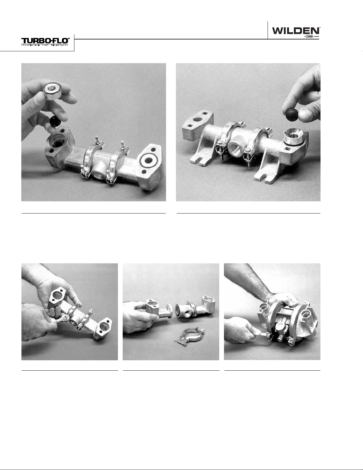
Step 4. Figure 4 Step 5. Figure 5
Step 6. Figure 6 Step 7. Figure 7 Step 8. Figure 8
Section 6
PUMP DISASSEMBLY
Remove the discharge valve balls, seats and o-rings
from the discharge manifold and inspect for nicks,
gouges, chemical attack or abrasive wear. Replace
worn parts with genuine Wilden parts for reliable
performance. PTFE o-rings should be replaced when
reassembled.
Inspect the ball retainer, retainer o-ring, and valve
ball from intake manifold. Check for nicks, gouges,
chemical attack or abrasive wear. Replace worn parts
with genuine Wilden parts for reliable performance.
PTFE o-rings should be replaced when reassembled.
Normally the inlet and discharge
manifoldshouldnotbedisassembled
during regular pump maintenance.
Should this be necessary completely
remove and disassemble manifold
clamp bands.
Inspect o-rings for wear or damage
and replace if necessary. PTFE
o-rings should be replaced when
reassembled.
Use a 7/16" wrench to remove one
set of clamp bands that secure one
liquid chamber to the one-piece
center section

13 WILDEN PUMP & ENGINEERING, LLCWIL-10190-E-03
Step 9. Figure 9 Step 10. Figure 10
Step 11A. Figure 11A Step 11B. Figure 11B Step 12. Figure 12
Section 6
PUMP DISASSEMBLY
Lift the liquid chamber away from the center section to
expose the diaphragm and outer piston.
Using an adjustable wrench, or by rotating the
diaphragm by hand, remove the diaphragm assembly
from the center section.
NOTE: Due to varying torque values,
one of the following two situations
may occur: 1) The outer piston,
diaphragm and inner piston remain
attached to the shaft and the entire
assembly can be removed from the
center section.
2)The outer piston, diaphragm, inner
piston, and disc spring separate from
the shaft which remains connected
to the opposite side diaphragm
assembly. PTFE-fitted pumps come
standard with back-up diaphragms
(not shown).
To remove the diaphragm assembly
from the shaft, secure shaft with soft
jaws (a vise fitted with plywood or
other suitable material) to ensure
shaft is not nicked, scratched, or
gouged.Using an adjustable wrench,
remove diaphragm assembly from
shaft.Inspect all parts for wear and
replace with genuine Wilden parts if
necessary.

14
WILDEN PUMP & ENGINEERING, LLC WIL-10190-E-03
The center section assembly consists of both the air valve
body and piston and the center section. The unique design
of the air valve relies only on differential pressure to cause
the air valve to shift. It is reliable and simple to maintain. The
bushing in the center block, along with the diaphragm shaft,
provides the signal to tell the air valve to shift. The following
procedure will ensure that the air valve on your Wilden pump
will provide long trouble-free service. valve piston does not move freely after the above cleaning, the
air valve should be disassembled as follows: Remove the snap
ring from the top end of the air valve cylinder and apply an air jet
to the 3.175mm (1/8”) hole on the opposite end of the air valve
face. [CAUTION: The air valve end cap (P/N 01-2330-23 may
come out with considerable force. Hand protection such as a
padded glove or a rag should be used to capture the end cap.]
Inspect the piston and cylinder bore for nicks and scoring.
Inspect the air valve side of the center section for flatness
and to insure no nicks or other damage exists that would
prevent the air valve from sealing when installed. Inspect the
two channels and their ports to make sure they are clean and
the ports are open to the bushing. The air valve will not shift if
these ports are plugged or an o-ring is in the wrong groove of
the center section closing off a port. Inspect the anti-centering
pin holes found at the ends of the air valve piston and ensure
they are free of debris. Inspect the air valve gasket and muffler
plate gasket and replace if damaged. Attach the air valve
to the center section and tighten to the required torque
specifications*.
AIR VALVE BODY AND PISTON
ASSEMBLY AND DISASSEMBLY
The air valve body and piston (P/N 01-2000-07) can be
disconnected from the pump by removing the four socket-
head cap screws which attach it to the center section. The
piston in the air valve is aluminum with a dark gray anodized
coating. The piston should move freely and the ports in the
piston should line up with the ports on the face of the air valve
body. The piston should also appear to be a dull, dark gray
color. If the piston appears to be a shiny aluminum color, the
air valve is probably worn beyond working tolerances and
should be replaced.
If the piston does not move freely in the air valve, the entire air
valve should be immersed in a cleaning solution. (NOTE: Do
not force the piston by inserting a metal object.) This soaking
should remove any accumulation of sludge and grit which is
preventing the air valve piston from moving freely. If the air
The pump’s center section consists of a molded housing with
a bronze bushing. (Bushing is not removable.) This bushing
has grooves cut into the inside diameter. o-rings are installed
in these grooves. When the o-rings become worn or flat, they
will no longer seal and must be replaced. This is most easily
accomplished by using a tool called an o-ring pick, available
through most industrial supply companies.
There are two versions of center sections: PRE-ENHANCED
(pumps manufactured before March 1, 1992) and ENHANCED
(pumps manufactured since March 1, 1992). An encircled
letter “E” stamped on the top of the center section denotes
the ENHANCED type center section (Figure C).
If the encircled “E” is not present, a pre-enhanced shaft
(01-3800-09) must be utilized. An enhanced (non-dented)
shaft will not function correctly in the pre-enhanced center
section. The center section o-rings (01-3200-52) must be
installed in the appropriate grooves as shown (1, 3, 4, 6).
If the encircled “E” is present, an enhanced (01-3800-
03-07) shaft should be utilized to maximize performance. The
center section o-rings (01-3200-52) must be installed in the
appropriate grooves as shown (1, 3, 6, 8).
Figure A
1 3 6 8
ENHANCED CONFIGURATION
ENHANCED SHAFT
1 3 4 6
PRE-ENHANCED CONFIGURATION
PRE-ENHANCED SHAFT
Figure C
*Refer to Section 8D for the required torque specifications.
Section 6
AIR VALVE / CENTER SECTION REPAIR/MAINT.
O-RING REPLACEMENT/CENTER SECTION

15 WILDEN PUMP & ENGINEERING, LLCWIL-10190-E-03
ASSEMBLY:
Upon performing applicable maintenance to the air distribution
system, the pump can now be reassembled. Please refer to
the disassembly instructions for photos and parts placement.
To reassemble the pump, follow the disassembly instructions in
reverse order. The air distribution system needs to be assem-
bled first, then the diaphragms and finally the wetted path.
Please find the applicable torque specifications on this page.
The following tips will assist in the assembly process.
• Clean the inside of the center section shaft bushing to
ensure no damage is done to new seals.
• Stainless bolts should be lubed to reduce the possibility of
seizing during tightening.
• Level the water chamber side of the intake/discharge mani-
fold to ensure a proper sealing surface. This is most easily
accomplished by placing them on a flat surface prior to
tightening their clamp bands to the desired torque (see this
page for torque specs).
• Be sure to tighten outer pistons simultaneously on PTFE-
fitted pumps to ensure proper torque values.
• Ensure proper mating of liquid chambers to manifolds prior
to tightening vertical bolts. Overhang should be equal on
both sides.
• Apply a small amount of Loctite 242 to the steel bore of the
shaft from the diaphragm assembly.
MAXIMUM TORQUE SPECIFICATIONS
Description of Part Metal Pumps
Air Valve 2.3 N•m (20 in-lbs)
Outer Piston 14.1 N•m (125 in-lbs)
Small Clamp Band 1.7 N•m (15 in-lbs)
Large Clamp Band (Rubber-Fitted) 7.4 N•m (65 in-lbs)
Large Clamp Band (Teflon®-Fitted) 9.6 N•m (85 in-lbs)
Vertical Bolts 14.1 N•m (125 in-lbs)
Section 6
REASSEMBLY HINTS & TIPS

16
WILDEN PUMP & ENGINEERING, LLC WIL-10190-E-03
Section 8
EXPLODED VIEW & PARTS LISTING
T1 METAL Rubber/TPE-Fitted EXPLODED VIEW

17 WILDEN PUMP & ENGINEERING, LLCWIL-10190-E-03
Rubber-Fitted
Item Part Description
Qty. Per
Pump
T1/AAYYB
P/N
T1/SSYYB
P/N
1 Air Valve Assembly11 01-2000-07 01-2000-07
2 Center Section 1 01-3153-23 01-3153-23
3 Center Block Glyd™ Ring 4 01-3220-55 01-3220-55
4 Shaft 1 01-3800-03-07 01-3800-03-07
5 Pistons/Outer 2 01-4570-01 01-4570-03
6 Pistons/Inner 2 01-3710-01 01-3710-01
7 Air Valve Gasket 1 01-2600-52 01-2600-52
8 Muffler Plate Gasket 1 01-3500-52 01-3500-52
9 Muffler Plate 1 01-3180-23 01-3180-23
10 End Cap w/Guide 1 01-2300-23 01-2300-23
11 End Cap w/o Guide 1 01-2330-23 01-2330-23
12 Buna-N O-Ring - 115 70 Shore 2 01-2390-52 01-2390-52
13 End Cap Snap Ring 2 01-2650-03 01-2650-03
14 Air Valve Cap Screw 1/4"-20 x 4-1/2" 4 01-6000-03 01-6000-03
15 Air Valve Cap Screw Nut 1⁄4"-20 4 04-6400-03 04-6400-03
16 Liquid Chamber 2 01-5000-01 01-5000-03
17 Discharge Manifold Elbow 2 01-5230-01 01-5230-03
18 Inlet Manifold Elbow 2 01-5220-01 01-5220-03
19 Manifold “T” Section 2 01-5160-01 01-5160-03
20 Clamp Band (Large) Assy. 2 01-7300-03 01-7300-03
21 Clamp Band (Small) Assy. 4 01-7100-03 01-7100-03
22 Vertical Bolt 1/4"-20 x 7-3/8" 4 01-6080-03 01-6080-03
23 Muffler 1 01-3510-99 01-3510-99
24 Diaphragm 2 * *
25 Valve Ball 4 * *
26 Valve Seat 4 01-1120-01 01-1120-03
27 Valve Seat O-Ring 4 * *
28 Manifold O-Ring 4 * *
29 Small Clamp Band Bolt #10-24 x 1" 8 01-6101-03 01-6101-03
30 Small Clamp Band Nut #10-24 8 01-6400-03 01-6400-03
31 Large Clamp Band Bolt 1/4"-20 x 1-3/4" 4 01-6070-03 01-6070-03
32 Large Clamp Band Nut 1/4"-20 4 04-6400-03 04-6400-03
33 Shaft Stud 2 N/A 01-6150-03
34 Vertical Bolt Nut 1/4"-20 4 04-6400-03 04-6400-03
35 Vertical Bolt Washer 4 01-6730-03 01-6730-03
36 Disc Spring 2 01-6802-08 01-6802-08
1Air Valve Assembly includes items 10, 11, 12, 13.
*Refer to corresponding elastomer chart in Section 9.
All boldface items are primary wear parts.
T1 METAL Rubber/TPE-Fitted PARTS LISTING
Section 6
EXPLODED VIEW & PARTS LISTING

18
WILDEN PUMP & ENGINEERING, LLC WIL-10190-E-03
NOTE: PTFE Diaphragm Models Assembled with
PTFE Gasket Kit At Factory (Not Shown)
Section 8
EXPLODED VIEW & PARTS LISTING
T1 METAL PTFE-Fitted EXPLODED VIEW
Table of contents
Other EOM Water Pump manuals

Popular Water Pump manuals by other brands

Ingersoll-Rand
Ingersoll-Rand ARO 650719-C Operator's manual

Maruyama
Maruyama MP2530CE Operator's manual

Mistral
Mistral MSP 12 A1 Translation of the original instructions

Pentair Jung Pumpen
Pentair Jung Pumpen Multistream 10/2 A1 instruction manual

BBC Elettropompe
BBC Elettropompe QM PT 7 instruction manual

AERMEC
AERMEC SAP 1500 manual

F.P.Z.
F.P.Z. VS6 Use instruction

Harvest Healthcare
Harvest Healthcare HARVEST 1 General User/ Safety Guide

Gardner Denver
Gardner Denver Wittig RFW 150 DV Operating and service manual

Wilo
Wilo Wilo-Drain TS 40/12 Installation and operating instructions

Biral
Biral EBZ-V manual

Masterflex
Masterflex MASTERSENSE MFLX07526-10 operating manual


