EP Solar SPP-01 User manual

Super Parameter Programmer
SPP-01
Dearuser:
Thank you very much for selectingour product!
This manual offers important information and suggestions about use and
troubleshooting,etc.Please read this manual carefullybefore using the
product.
Warranty: The product is warranted to be free fromdefects for a period of
two years fromthe dateofshipment to theoriginal enduser.

Contents
1 Important Safety Information ............................................1
2 General Information ........................................................1
2.1 Product Characteristic ...................................................1
2.2 Main Functions............................................................2
2.3 Recommendation .........................................................2
3 Features ........................................................................3
3.1 Features......................................................................3
3.2 Power Supply and Startup..............................................5
4 Software Operation .........................................................7
4.1 Software Operating Environment.....................................7
4.2 Software Installation and Uninstalling..............................7
4.3 Software Operating Instructions ......................................7
5 Specification................................................................ 22
5.1 Hardware Configuration .............................................. 22
5.2 SPP-01 Parameter....................................................... 22
6 SPP-01 Overall Dimension............................................. 23

1
1 Important Safety Information
This manual contains important safety,setting and operating instructions for
SPP-01. Save these instructions.
Please inspect the productthoroughly after it is delivered. Ifany damage
is seen, please notify the shipping company or our company
immediately.
Readofthe instructions and cautions in the manualbefore using.
Keep the product away from rain, exposure, severe dust, vibrations,
corrosive gas andintense electromagnetic interference.
Donot allow waterto enter the controller.
Donotdisassembleor attempt to repairit.
2 General Information
2.1 Product Characteristic
Super parameter programmer (SPP-01) is the simple, efficient and practical
accessory for parameter configuration with the easy one button operation.
Due to the new standard communication protocol, it applies to stand-alone
or multi-parallel products. The features ofthe SPP-01 are listed below.
One button and one indication led are designed for simplicity and
easy-to-operate.
RS232 (TTL), RS485 and USB communication are supported.
SPPPCTools PC software is used to configure and backup parameters

2
visually, rapidly and conveniently.
Dual power supply design. SPP-01 can be powered by battery or
Micro-USB cable applying for various environments.
2.2 Main Functions
Parameter configuration function
Load the parameter configuration to the SPP-01 via SPPPCTools PC
software andthenupdate thedevice’s parametersthrough SPP-01 with
easy one button.
Data transparent transmission function.
SPP-01 can be used as the communication converter to connect the
device and Solar Station Monitor, a PC software, to establish remote
monitoring.
2.3 Recommendation
DCCPxxxxDP (R), LSxxxxB (PL), VSxxxxB, TracerxxxxB (PL) and
iTracerxxB series products are supported to update the configuration by
SPP-01.Please confirmwhether to support beforepurchasing.

3
3 Features
3.1 Features
Description
Operation
Remarks
K1(Toggle
switch1)
COM
Communication converter mode
MEM
Parameter configuration mode
K2(Toggle
switch 2)
Line
Wire communication mode
IrDA
Reserved
K3(Toggle
switch 3)
On
Power on
Off
Power off
K4(Water proof
key4)
Press the button
Press the key to enter configuration
mode (theindicatorledison), click
it again to update the configuration.
Press and hold
thebutton
Test“Turn on” or “ Turn off” the
load.
Indicator led and
buzzer
Configuration
mode
The indicator led is onwithout a
beep.
Update
The indicator led flashes once
K1
K2
K3
LED
K4

4
successfully.
with one shortbeep.
Communication
error
The indicator led flashes twice
with two short beeps.
The model is not
matched orthe
irrational
configuration
The indicator led flashes triple
with threeshort beeps.
Test
The indicator light flashes for
severaltimeswith onelong beep.
Note:
1. Press and hold the button for three seconds to alternately turn onor turn
offthe load in the testing mode. After3 minutes, the device will quit the
test mode automatically.
2. In the testing mode, the SPP-01 can switch theload no matter whetherit
hasloadedthe configuration ornot.
RJ11
RJ45

5
Description
Operating
Remarks
RJ11interface
Connectthe controllerwith the
CC-TTL-TTL-150U communication
cable
Update device
configure
RJ45interface
Connectthe controllerwith the
CC-RS485- RS485-150U
communication cable
Update device
configure
USBinterface
ConnecttothePC with the
CC-USB-USB-150U communication
cable
Update SPP01
configure
RTC battery
holder
Battery for real-time time clock
Type: CR1220
Battery
compartment
3 batteries
SizeAAA
3.2 Power Supply and Startup
The SPP-01ispowered by following three methods:
1. Getpower via theUSBdata cable fromUSB interface.
RTC Battery
Battery compartment
USBinterface

6
2. Getpower via exclusive data cable fromthedevice.
3. Getpower from3 batteries (sizeAAA).
Starting SPP-01: The SPP-01 ispoweredon by toggling K3 switch to “ ON”
Operating status
Phenomena
Normal startup
The greenlight flashes oncewith one beep.
Nodata availablein
SPP-01
The greenlight flashes for several times with
severalbeeps.

7
4 Software Operation
4.1 Software Operating Environment
Hardware Environment
APentium4-compatiblePC
At least 512MbyteofRAM and 55Mbyte offree disk space
Software Operating Environment
The recommendedoperatingsystemis as follows:
Windows XP (32bit),Win7 (32bit/64bit),Win8 (32bit/64bit)
Installing component:Windows Installer3_1, DotNetFX40.
4.2 Software Installation and Uninstalling
Installing the software
Open directory “ SPPPCSoftwareV3.77”, and double click “setup.exe”,
after the computerstart carryon the software gearing.
Uninstalling thesoftware
Clickthe Start >ControlPanel >Add or delete programs> SPP>Delete.
4.3 Software Operating Instructions
Get serial port numberfor SPP-01
1. Connectthedevice: Connect SPP-01 to thePCwith the Micro-USB
cable and turn K3switch to “ ON” position. The SPP-01starts normally
with indicator led flashing once and a short beep.
8
2. Install SPP-01 serialport driver: Open directory “SPPUSBDriver” and
run “ Setup.bat” file to install thedriver.
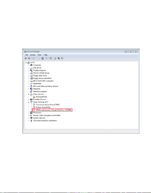
3. Right click “My computer > Property > Hardware > Device manager”
topopup adevice managerwindow, seeing the figure below:
Note: The serial port number selected in the figure above is the serial
portnumberofSPP-01 (COM8).

9
Main interface
Parameter configure:
1. Double click software icon to pop up configuration interface of
SPP-01.
2. The softwarewill automatically open the port afterselectedserial port of
SPP-01(thebutton caption will change from “open port” to “ close port”)
3. The following dialog box will be popped up automatically by clicking
“SELECT” tag:
10
Double click to select device (the configuration content will be changed
automatically).
4. Configure relevant parameters by clicking “ Control P arameters”,
“General Load”, “ LED Load” in the frame of Parameter Configuration
and “Time Sync” in the Management. After configuring parameters,
click “ OK” to quit and return to main interface (For the parameters
without configuration, uncheck the box “ ”).
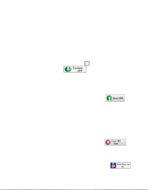
5. After configuration, click button to load configuration
into SPP-01 device (a corresponding dialog box will be popped up to
prompt whether loaded successfully or not).
Reading parameter data
Ifthe configuration has beenloaded tothe SPP-0, click
button to upload the configuration in SPP-01 to PC, and refresh the
corresponding parameter configuration in “ Parameter configuration”
frame, such as ControlParameter,General Load orLED Load, Time
Sync so astoview and modify the parameters.
Data clearing
Ifit is requiredto clear configuration in SPP-01,click
button directly.
Importing and exporting parameter configuration
If it is required to backup parameter configuration, click

11
button to save the configuration as a text file with extension of.TXT. If
it is required to import configuration backed up previously, click
button to load corresponding TXT file to upload the
configuration.
Control Parameter
Batterytype
Batterytype
Notes
Sealed (default)
Fixed controlling voltage,unable to be modified
Gel
Fixed controlling voltage,unable to be modified
Flooded
Fixed controlling voltage,unable to be modified
User
Users can modify voltage controlling points.

12
Charging Mode
Charging mode
Notes
Voltage
compensation
Voltage control charging (default)
SOC
Set the charge anddischarge SOCtargetvalues for
battery charge and discharge control
Other ControlParameter
Parameters
Default
Range
BatteryAh
200Ah
1~9999Ah
Temperature
compensation
coefficient
-3mV/ºC/2V
-9~-0mV
Rated Voltage
Auto
Auto/12V/24V/36V/48V
Battery charging
100%
100%(SOC Mode)
Batterydischarging
30%
10~80%(SOC Mode)
Note: Battery charging voltage ≥Battery discharge+10% or battery
discharge value ≤Battery charge-10% value
Battery VoltageParameters (values arein 12V systemat 25ºC, please
doublein 24V, triple in 36 V, and quadruplein 48 Vsystem)
Batterytype
Sealed
Gel
Flooded
User
High Volt Disconnect
16V
16V
16V
9~17V
Charging Limit Voltage
15V
15V
15V
9~17V
Over Voltage Reconnect
15V
15V
15V
9~17V
Equalize Charging
——
14.6V
14.8V
9~17V

13
Boost Charging Voltage
14.2V
14.4V
14.6V
9~17V
Float Charging Voltage
13.8V
13.8V
13.8V
9~17V
Boost Return Voltage
13.2V
13.2V
13.2V
9~17V
Low Voltage Reconnect
12.6V
12.6V
12.6V
9~17V
Under Voltage Recover
12.2V
12.2V
12.2V
9~17V
Under Voltage Warning
12V
12V
12V
9~17V
Low Voltage Disconnect
Voltage
11.1V
11.1V
11.1V
9~17V
Discharging Limit
Voltage
10.6V
10.6V
10.6V
9~17V
Equalize Duration
——
120
Min.
120
Min.
0~180
Min.
Boost Duration
120
Min.
120
Min.
120
Min.
10~180
Min.
Note: The following rules must be observed when modify the parameters
valueinuser batterytype (factory default value is the same assealed type):
High Volt Disconnect > Charging limit voltage ≥Equalization voltage
≥ Boost voltage ≥Float voltage > Boost return voltage
High VoltDisconnect >Over Voltage Reconnect
Low Voltage Reconnect > Low Voltage Disconnect ≥ Discharging
Limit Voltage
Under Voltage Warning Reconnect > Under Voltage Warning ≥
Discharging Limit Voltage
Boost Reconnect Charging voltage >Low VoltageDisconnect


15
Offby default
Controllerkeep the load output offbefore, during and
after initialized. The load canbe switched ononly when
doing “ Manual On bydefault” operation and the battery
is enough electricity andno abnormalsituation.
Time Control
Time1(T1)
Control on/offtime1 ofload through real-time clock
mode.
Time2(T2)
Control on/offtime2 ofload in dual time mode.
Light ON/OFF
Light ON Voltage
Wheninputvoltage ofsolar modulegoes below light
ON voltage, the solar controllerwill recognizethe
starting voltage and turn on the load after pre-set time
delaywhenthe batterypoweris enough andthe
controllerworks well.
Light OFF Voltage
Wheninputvoltage ofsolar modulegoes abovelight
OFFvoltage,thesolar controller will recognize the
starting voltage and turn offthe load after pre-set time
delay.
Delay Time
The confirmation time for Light signal. During the
period, iflight signal voltage continues matching Light
ON/OFFvoltage,it will carry out corresponding actions
(The time adjustment range:0~99mins.

16
Light ON+ Timer
Working Time 1
(T1)
Loadworking period after light control turnsON load
Working Time 2
(T2)
Loadworking period beforelight control turns OFFload
Night Time
The controller calculatedthe total lengthofthenightby
self-learning. The time should be morethan3 hours
Light Control +Time Model Diagram

17
LED Load Configuration
LEDLoad parameter
Parameter
Remark
LED Rated Current
Rated output current.
LED Rated Current
Percentage
Set uptheparameterofthe rated currentpercentageofthe
corresponding operating periodofthe controller; the
controllerwill control theLEDload output current
according to this value.

18
BatteryUnder
Voltage Control
When the battery is underthis voltage, theoutput current
will behalf;whenthevoltage ofthe batterygoes aboveit,
the controller will resume the set currentvalue
automatically.
Manual Control(load can be switched by manual button or remote
control command)
Manually On By
default
Controllerswitches on the load output once initialized
andkeep constant output on condition that the battery
is enough electricity andno abnormalsituation.
Manually Off
By default
Controllerkeep the load output offbefore, during and
after initialized. The load canbe switched ononly
whendoing “Manual On by default” operation and the
battery is enough electricity and no abnormal situation.
Time Control
Time1(T1)
Control on/off time1 of load through real-time clock
mode.
Time2(T2)
Control on/offtime2 ofload in dual time mode.
Light ON/OFF
Light ON
Voltage
Wheninputvoltage ofsolar modulegoes below light
ON voltage, the solar controllerwill recognizethe
starting voltage and turnon the load after pre-set time
delaywhenthe batterypoweris enough andthe
controllerworks well.
Table of contents


