QDI Advance 6T User manual

Declaration of Conformity
QUANTUMDESIGNS(HK)LTD.
20th Floor, Devon House, Taikoo Place, 979 King’s Road,
Quarry Bay, Hong Kong
declares that the product
Motherboard
Advance 6T
is in conformity with
(reference to the specification under which conformity is declared in
accordance with 89/336 EEC-EMC Directive
!"EN 55022 Limits and methods of measurements of radio disturbance
characteristics of information technology equipment
!"EN 50081-1 Generic emission standard art 1:
Residential, commercial and light industry
!"EN 50082-1 Generic immunity standard art 1:
Residential, commercial and light industry
European Representative:
QDI COM UTER( UK ) LTD. QDI COM UTER( SCANDINAVIA )A/S
QDI SYSTEM HANDEL GMBH QDI EURO E B.V
QDI COM UTER( FRANCE ) SARL QDI COM UTER HANDELS GMBH
LEGEND QDI S AIN S.L QDI COM UTER( SWEDEN )AB
Signature : lace / Date : HONG KONG/2001
rinted Name : Xu Wenge osition/ Title : Assistant resident

Declaration of Conformity
Trade Name: QDI Computer ( U. S . A. Inc.
Model Name: Advance 6T
Responsible Party: QDI Computer ( U. S. A. Inc.
Address: 41456 Christy Street
Fremont, CA 94538
Telephone: (510 668-4933
Facsimile: (510 668-4966
Equipment Classification: FCC Class B Subassembly
Type of Product: Motherboard
Manufacturer:Quantum Designs (HK) Inc.
Address: 20th Floor, Devon House, Taikoo Place
979 Kings Road, Quarry Bay, HONG
KONG
Supplementary Information:
This device complies with Part 15 of the FCC Rules. peration is subject to
the following two conditions : (1) this device may not cause harmful interfer-
ence, and (2) this device must accept any interference received, including
interference that may cause undesired operation.
Tested to comply with FCC standards.
Signature : Date : 2001

1. Introduction...........................................1
Overview........................................................................ 1
Key Features.................................................................. 1
1
2. Installation Instructions......................... 4
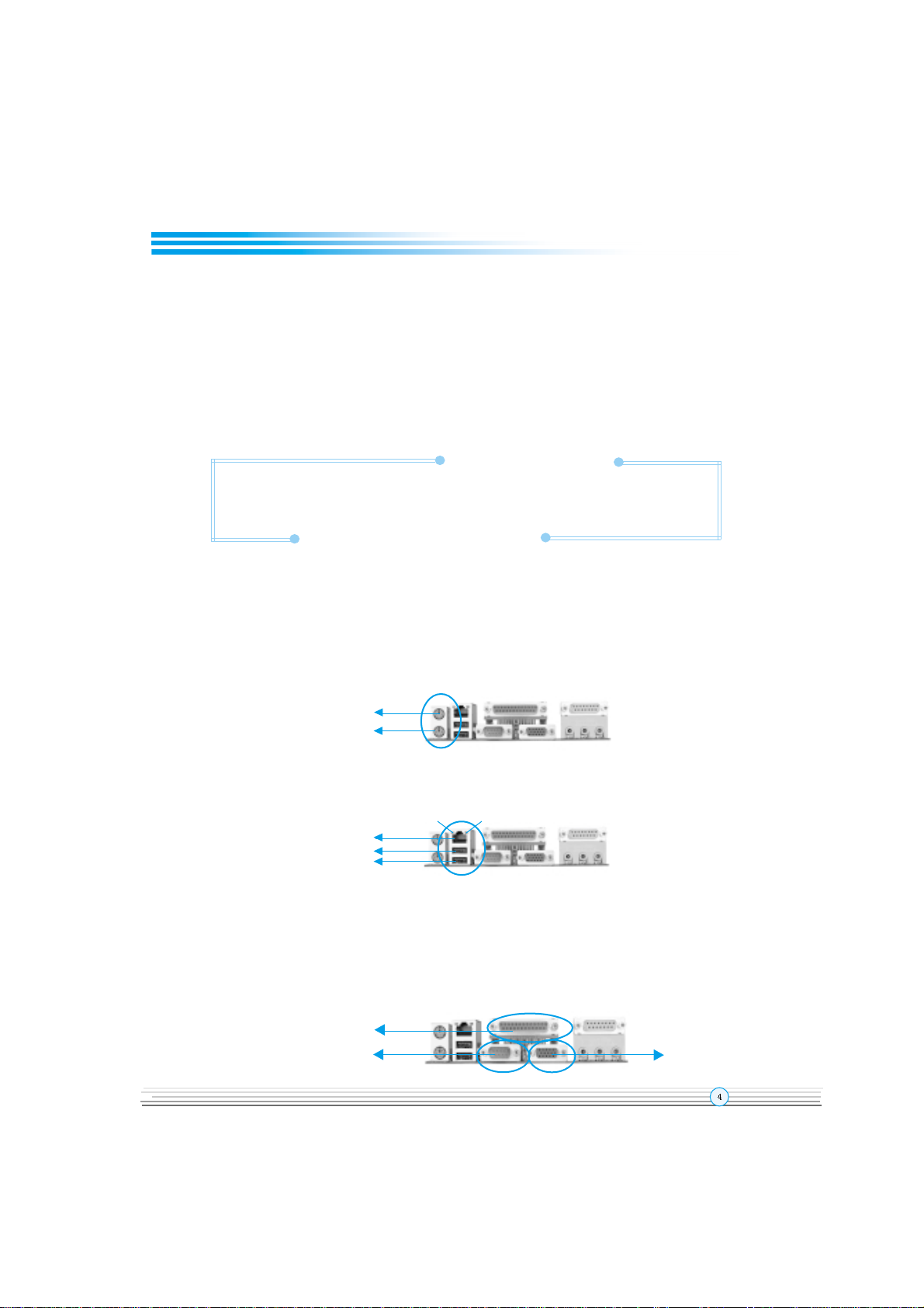
ExternalConnectors.................................................4
PS/2 Keyboard & PS/2 Mouse Connectors.....................4
USB1 USB2 and LAN Connectors( optional )................ 4
Parallel Port Connector and Serial Port Connector
( UART1 )Monitor Output Connector(VGA).................... 4
Line-in jack Microphone-in jack Speaker-out jack and
MIDI/Joystick Connector.................................................. 5
USB3 USB4 Connectors................................................ 5
Serial Port Connector( UART2 ) ......................................5
Fan Connectors(CPUFAN CHSFAN BAKFAN)............. 6
Internal Audio Connectors (CD_IN MODEM)...................6
ATX Power Supply Connector & Power Switch.............7
Hard Disk LED Connector (HD_LED) ..............................7
Reset Switch (RESET)....................................................7
Speaker Connector (SPEAKER)......................................7
Power LED Connector(PWR_LED) ................................ 7
ACPI LED Connector(ACPI LED)......................................7
Green LED Connector (GREEN LED)............................. 8
Hardware Green Connector (SLEEP).............................8
Audio/Modem Riser Slot(AMR)........................................8
Wake-Up On LAN (WOL) ............................................. 9
Wake-Up On Internal Modem (WOM).............................. 9
Audio Interface(Reserved).............................................10
JumperSettings........................................................ 11
Enable Front/Back Panel USB Device Wake-up
Function (JUSB1 JUSB2)................................................ 11
FSB Frequency Selection(JFSB1 JFSB2)......................12
Overclocking Jumper Setting(JCLK1 JCLK2)................. 13
II
CONTENTSCONTENTS
CONTENTSCONTENTS
CONTENTS

CPU Bus Ratio Selection(JX1 JX2 JX3 JX4)................ 14
Enable/Disable On-board audio(JSD)............................. 15
Clear CMOS(JCC)........................................................... 15
BIOS-ProtectEasy Jumper(JAV)......................................16
Enable/Disable On-board LAN( J3 )( optional )................16
3. BIOS Description....................................17
UtilitySupport............................................................. 17
AWDFLASH.EXE.............................................................17
AWARD BIOSDescription........................................18
Entering Setup................................................................ 18
Load Optimized Defaults.................................................18
Standard CMOS Features Setup.....................................18
Advanced BIOS Features Setup.....................................22
Advanced Chipset Features Setup.................................24
Power Management Setup ............................................26
PNP/PCI Configurations Setup.........................................29
Integrated Peripherals ..................................................30
PC Health Status..............................................................32
Supervisor/User Password............................................33
Appendix
QDI Driver CD 2000....................................................34
QDI ManageEasy............................................................ 35
BIOS-ProtectEasy........................................................... 35
Norton AntiVirus............................................................. 35
LogoEasy......................................................................36
RecoveryEasy................................................................ 37
QDI BootEasy.................................................................. 45
New Features.................................................................49
Advance 6T (French)..................................................... 50
Layout
II
CONTENTSCONTENTS
CONTENTSCONTENTS
CONTENTS

Manual for Advance 6T series
Chapter 1
Chapter 1
Introduction
Overview
The Advance 6T series are high performance cost-effective and energy efficient mainboards
from 66MHz 100MHz and 133MHz based on Socket-370 processors. The green mainboard
utilizes the VIA Apollo PLE133T chipset consisting of the VIA VT8601T( North Bridge ) and
the VIA VT82C686B( South Bridge ). The chipset integrates AGP 2D/3D graphics accelera-
tor to provide high graphics performance. It supports the UltraDMA 33/66/100 IDE PC100/
PC133 SDRAM and AC97 audio. In addition advanced features are supported such as
wake-up on LAN wake-up on internal/external modem ACPI power management and hard-
ware monitoring.ManageEasy our system management application is also supplied to
enable remote monitoring and configuration of the system. BootEasy lets the PC boot
freely and rapidly.
Key Features
Form Factor
#"mATX form factor of 244mm x210mm
Microprocessor
#"Supports 66/100/133MHz FSB speed
#"Supports all Intel® Pentium III(Coppermine) FC-PGA processors at 600EB/667/733/
800EB/866/933MHz/1GHz and future processors with 133MHz FSB speed
#"Supports all Intel® Pentium III(Coppermine) FC-PGA processors at 500/550/600/650/
700/750/800/850MHz and future processors with 100MHz FSB speed
#"Supports all Intel® Celeron FC-PGA processors at 533/566/600/633/667/700/733/
766MHz and future processors with 66MHz FSB speed
#"Supports all Intel® Celeron FC-PGA processors at 800/850/900/950MHz and future
processors with 100MHz FSB speed
#"Supports all Intel® Tualatin Pentium® III/ CeleronTM
FC-PGA2 processors at 1.13/1.20/
1.26GHz and future processors
#"Supports VIA C3(Samuel 2) 700/733/750/800MHz and future processors
Chipset
#"VIA Apollo PLE133T chipset: VT8601T VT82C686B
Memory
#" Provides two 168-pin 3.3V unbuffered 100/133MHz DIMM sockets
#"Supports PC100/PC133 SDRAM

Manual for Advance 6T series
Introduction
Onboard IDE
##
##
#" Supports two PCI PIO and Bus Master IDE ports
##
##
#""
""
"Two fast IDE interfaces supporting up to four IDE devices including IDE hard disks
and CDROM drives
##
##
#""
""
"Supports up to mode 4 timing
##
##
#""
""
"Supports Ultra DMA33/66/100
Onboard I/O
##
##
#""
""
"One floppy port supporting up to two 3.5 or 5.25 floppy drives with 360K/720K/
1.2M/1.44M/2.88M format
##
##
#""
""
"Two high speed 16550 fast compatible UARTs(COM1/COM2/COM3/COM4
selective) with 16-byte transmit/receiver FIFOs(UART2 is optional)
##
##
#""
""
"One enabled parallel port at the I/O address 378H/278H/3BCH with additional
bidirection I/O capability and multi-mode as SPP/EPP/ECP (IEEE 1284 compliant)
##
##
#""
""
"Supports PS/2 mouse and PS/2 keyboard
##
##
#""
""
"Provides four USB ports
##
##
#""
""
"Supports LS-120 floppy disk drive and Zip drive
##
##
#""
""
"All I/O ports can be enabled/disabled in the BIOS setup
OnboardAudio
##
##
#""
""
"Standard AC97 Codec interface
OnboardAGP
##
##
#""
""
"Supports AGP 4x
##
##
#""
""
"Integrated 2D/3D Graphics Controller
##
##
#""
""
"Supports 2~ 8Mbytes of Frame Buffer
Onboard LAN( optional )
##
##
#""
""
"Provides One 10/100M LAN interface
##
##
#""
""
"10/100 Mbit/sec Ethernet support
Advanced Features
##
##
#""
""
"PCI- 2.2 compliant
##
##
#""
""
"Provides Trend ChipAwayVirus® On Guard
##
##
#""
""
"Supports wake-up on LAN
##
##
#""
""
"Supports wake-up on internal/external modem
##
##
#""
""
"Supports system monitoring (monitors system temperature CPU temperature voltages
and fan speed)

Manual for Advance 6T series
Chapter 1
##
##
#Supports QDI innovations: BootEasy LogoEasy RecoveryEasy BIOS-ProtectEasy
and ManageEasy
##
##
#Protects the system BIOS from being attacked by severe virus such as CIH by
enabling Flash Write Protect in CMOS setup or closing the Jumper JAV
BIOS
##
##
#Licensed advanced AWARD( Phoenix ) BIOS
##
##
#""
""
" Supports Flash ROM with 2M-bit memory size plug and play ready
##
##
#Supports IDE CDROM or SCSI bootup
Green Function
##
##
#""
""
" Supports ACPI (Advanced Configuration and Power Interface) and ODPM (OS
Directed Power Management)
#" Supports ACPI power status: S0( Full-on ) S1( Suspend ) S4(STD suspend
to Disk)(depending on OS ) S5(Soft-off)
Main Expansion Slots and Connectors
Slot/Port (Quantity) Description
PCI( 3 ) PCI slots
ISA( 1 ) ISA slot
IDE( 2 ) IDE ports
FLOPPY( 1 ) Floppy Drive port
DIMM( 2 ) DIMM sockets
USB( 4 ) USB connectors
VGA( 1 ) VGA connector
PARALLEL( 1 ) Parallel connector
AMR( 1 ) AMR slot
MIDI/Joystick( 1 ) MIDI/Joystick connector

Manual for Advance 6T series
-- T is page is intentionally left blank--

Manual for Advance 6T series
Chapter 2
Installation Instructions
This section covers External Connectors and Jumper Settings. Refer to the motherboard
layout chart for the locations of all jumpers external connectors slots and I/O ports.
Furthermore this section lists all necessary connector pin assignments for your reference.
The particular states of the jumpers connectors and ports are illustrated in the following
figures. Before setting the jumpers or inserting these connectors please pay attention to
the directions.
Be sure to unplug the AC power supply before adding or removing expansion
cards or other system peripherals, otherwise your motherboard and expan-
sion cards might be seriously damaged.
External Connectors
PS/2 Keyboard Connector, PS/2 Mouse Connector
PS/2 keyboard connector is for the usage of PS/2 keyboard. If using a standard AT size
keyboard an adapter should be used to fit this connector. PS/2 mouse connector is for the
usage of PS/2 mouse.
USB1, USB2 and LAN Connectors( LAN Connector is optional )
Two USB ports are for connecting USB devices. The RJ-45 connector is for onboard LAN.
Parallel Port, Serial Port Connector( UART1 ), Monitor Output Connec-
tor( VGA )
The parallel port connector can be connected to a parallel device such as a printer. The
serial port UART1 connector can be connected to a serial port device such as a serial port
mouse. The VGA connector is for output to a VGA-compatible device. You can enable/
disable them and choose the IRQ or I/O address in INTEGRATED PERIPHERALS in AWARD
BIOS SETUP.
Chapter 2
PS/2 Mouse Connector
PS/2 Keyboard Connector
USB1
USB2
LAN(optional)
L NK ACT VE
Parallel Port
UART1 VGA

Manual for Advance 6T series
Line-in jack, Microphone-in jack, Speaker-out jack and
MIDI/Joystick Connector
The Line-in jack can be connected to devices such as a cassette or minidisc player for
playback or recording. The Microphone-in jack can be connected to a microphone for voice
input. The Speaker-out jack allows you to connect speakers or headphones for audio
output from the internal amplifier.
The MIDI/Joystick connector allows you to connect a game joystick or a MIDI device.
USB3, USB4Connector
Besides USB1 2 on the back panel the mainboard also have a 10-pin header on board which
may connect to a front panel USB cable to provide additional two USB ports.
Serial Port Connector( UART2 )(optional)
Besides UART1 on the back panel the mainboard also have a header on board which may
connect to a cable to provide an additional UART port.
Installation Instruction
MIDI/Joystick
Speaker out Line in Microphone in
+5v
D3-
D3+
GND
GND
GND
GND
D4+
D4-
+5v
USB3,4
UART2
1
1

Manual for Advance 6T series
FanConnectors(CPUFAN,CHSFAN, BAKFAN)
The fan speeds of CPUFAN and CHSFAN can be detected and viewed in PC HEALTH
section of the BIOS. These fans will be automatically turned off after the system enters
suspend mode.
Internal Audio Connectors (CD_IN, MODEM)
CD_IN connector allows you to receive audio input from such sound sources as a CD-ROM
TV tuner or MPEG card. The MODEM connector allows the onboard audio to interface with
a voice modem card with a similar connector. It also allows the sharing of mono_in (such as
a phone) and mono_out (such as a speaker) between the onboard audio and the voice
modem card.
Chapter 2
SENSE
GND
+12V
SENSE
CPUFAN
+12V
NC
BAKFAN
GND
+12V
CHSFAN
GND
1
1
1
CD_IN
Common
Right Channel Left Channel
Mono-Out (to Modem)
GND
MOD M
Phone- n (from Modem)
1
1

Manual for Advance 6T series
Installation Instruction
ATX Power Supply Connector & Power Switch( POWER SW )
Be sure to connect the power supply plug to this connector in its proper orientation. The
power switch ( POWER SW ) should be connected to a momentary switch (power button).
When powering up your system first turn on the mechanical switch of the power supply (if
one is provided) then push once the power button. When powering off the system you
neednt turn off the mechanical switch just
Push once
*the power button.
Note: * If you change “soft-off by PWRBTN” from default “Instant-off” to “Delay 4
Sec” in the “POWER MANAGEMENT SETUP” section of the BIOS, the power button
should be pressed for more than 4 seconds before the system powers down.
Hard Disk LED Connector (HD_ LED)
The connector connects to the cases IDE indicator LED indicating the activity status of IDE
hard disk. The connector has an orientation. If one way doesnt work try the other way.
Reset Switch (RESET)
The connector connects to the cases reset switch. Press the switch once the system
resets.
Speaker Connector (SPEAKER)
The connector can be connected to the speaker on the case.
Power LED Connector (PWR_LED)
When the system is in S0( full-on ) status the LED is on. When the system is in S1( suspend)
status the LED is blink. When the system is in S4( STD ) or S5( soft-off ) status the LED is
off. The connector has an orientation.
ACPI LED Connector (ACPI LED)
The ACPI LED is a double-color light with three pins. Pin1and Pin2 drive different color lights.
If Pin1 drives the orange light then Pin2 drives the green light the following status will
come out. When the system is in S0 status the LED is green on. When the system is in S1
status the LED is green blink. When the system is in S4 or S5 status the LED is off.
POWER SW
ATX Power Supply Connector
3.3V -12V GND PSON GND GND GND -5V 5V 5V
3.3V 3.3V GND 5V GND 5V GND PW-OK 5VSB 12V

Manual for Advance 6T series
GREENLEDConnector(GREENLED)
When the system is in S0 status ACPI S1 S4 or S5 status the LED is off. When the system
is in APM suspend status the LED is on.
Hardware Green Connector (SLEEP)
Push once the switch connected to this header the system enters suspend mode.
HD_LED
SPEAKER
ACP LED
RESET
POWER
SW
SLEEP
GREEN LED KEYLK
PWR_LED
SPEAKER RESET GREEN LED KEYLK
ACP LED SLEEP PWR_ LED
HDD LED(+) HDD LED(-)
ORANGE(-)
GREEN(-)
LED+
POWER
GND
EMPTY
EMPTY
SLEEP
GND
LED+
LED-
LED- KEYLOCK
GND
LED-
LED-
LED+
EMPTY
GND
RESET
SPKDATA
NC
GND
VCC
POWER
SW
Chapter 2
Audio/Modem Riser Slot( AMR )
The AMR Interface Connector is the interface between the mainboard and the Audio/
Modem Riser card. The connector provides all necessary signals which supports several
different configurations of audio and modem in the system such as audio and modem on
the riser audio on the mainboard and modem on the riser or no audio with modem on the
riser. Either AMR (Audio/Modem Riser) card or MR (Modem Riser) card can be used on this
system. To avoid conflict the onboard audio can be disabled by jumper JSD when using
codec on AMR card.
IrDA
1
AMR Slot

Manual for Advance 6T series
Wake-Up On LAN ( WOL )
Through the Wake-Up On LAN function a wake event occurring from the network can
wake up the system. If this function is to be used please be sure an ATX 2.01 power supply
of which 5VSB line is capable of delivering 720mA and a LAN adapter which supports this
function are used. Then connect this header to the relevant connector on the LAN adapter
set Wake up on LAN/Ring as Enabled in the POWER MANAGEMENT SETUP section of the
BIOS. Save & exit then boot the operating system once to make sure this function takes
effect.
Wake-Up On Internal Modem (WOM)
Through the Wake-Up On Internal Modem function the system which is in the suspend or
soft-off status can be powered on by a ring signal received from internal modem. If this
function is to be used be sure an internal modem card which supports the function is used.
Then connect this header to the relevant connector on the modem card set Wake up on
LAN/Ring as Enabled in the POWER MANAGEMENT SETUP section of the BIOS. Save &
exit then boot the operating system once to make sure this function takes effect.
Installation Instruction
+5V SB
GND
Signal for waking up (active high)
+5V SB
GND
Signal for waking up (active low)
WOL
1
WOM
1

Manual for Advance 6T series
Chapter 2
Audio Interface(Reserved)
The audio interface provides three kinds of audio output choices: the FrontAudio the
RearAudio and the ActiveAudio. Their priority level is as sequence. When the FrontAudio
is available the RearAudio and the ActiveAudio( in-case speakers ) will be cut off. When
the RearAudio is available the ActiveAudio will be cut off. An onboard amplifier is pro-
vided for the case of earphone plugged into. When the FrontAudio is absent Pin11 and
Pin12 Pin13 and Pin14 must be short connected.
FrontLineOutR
FrontLineOutL
LineNextR
LineNextL
GND
Speaker Out
Line in
Microphone in
Speaker
Earphone
Pin
No.
Symbol Pin
No.
Symbol
1 Active LINE Out(L) 2 ActiveLINE Out(R)
3 GND (ALO) 4 GND (ALO)
GND(+12) 6 GND(+12)
7 +12V(1A) 8 (Cut away )
9 MIC 10 GND ( MIC )
11 Front LINE Out( R ) 12 LINE Next( R )
13 Front LINE Out( L ) 14 LINE Next( L )
1 GND (FLO) 16 (Cut away )
Audio Interface
4
6
8
10
12
14
16 2
1
3
5
7
9
11
1315

Manual for Advance 6T series
Installation Instruction
3-pin
2-pin
set pin1 and pin2 closed
Symbol
Jumper
set the pins closed
set pin2 and pin3 closed
set the pins opened
Description
Jumper Settings
Jumpers are located on the mainboard they represent clear CMOS jumper JCC enable
BIOS ProtectEasy function jumper JAV etc. Pin 1 for all jumpers are located on the side with
a thick white line ( Pin1→ ) refer to the mainboards silkscreen . Jumpers with
three pins will be shown as to represent pin1 & pin2 connected and to
represent pin2 & pin3 connected.
Enable Front/Back Panel USB Device Wake-up Function (JUSB1/JUSB2)
The mainboard provides the advanced USB device wake-up function. The system can be
waked up from its power saving including ACPI S3 by activating USB device. Before using
this function set JUSB1/JUSB2 with pin1 & pin2 closed. Otherwise set JUSB1/JUSB2
with pin2 & pin3 closed for disabling. Furthermore the item Wake-Up From S3 by USBin
BIOS setup should also be set corespondingly to enable or disable this function.
JUSB2
JUSB1 Disable:
Enable:
(Default)
JUSB2
JUSB2
JUSB1
JUSB1
1
2
3
1
2
3
12 3
12 3

Manual for Advance 6T series
FSB Frequency Selection(JFSB1, JFSB2)
The jumper labeled JFSB1 and JFSB2 are located on the mainboard providing users with
FSB frequency selection. If it is set as Auto with JFSB1 and JFSB2 closed the system
detects the CPU front side bus automatically. If it is set as Jumper setting with JFSB1 and
JFSB2 opened the CPU front side bus can be set manually.
Chapter 2
JFSB1
JFSB2
1
1
22
FSB Selection
Auto
Jumper
JFSB1 JFSB2
Close Close
Open Open

Manual for Advance 6T series
Overclocking Jumper Setting (JCLK1, JCLK2)
Jumpers labeled JCLK1 JCLK2 are located on the motherboard providing users with CPU
overclocking feature. The host bus speed can be set as 66/100/133MHz. The table below for
your reference.
JCLK1
in2& in3 closed
C U FSB
66MHz
100MHz
133MHz
in1& in2 closed
JCLK2
in2& in3 closed
in2& in3 closed
in1& in2 closed in1& in2 closed
Note: Whether or not your system can be overclocked depends on your
processor’ s capability. We do not guarantee the overclocking system to be stable.
We will not be responsible for any damages caused.
1
JCLK1 JCLK2
123 23
Installation Instruction

Manual for Advance 6T series
CPU Bus Ratio Selection (JX1, JX2,JX3, JX4)
The Host Bus speed by the CPU bus ratio equals the CPUs internal frequency (CPU speed)
IfHost Bus speed = 100MHz CPU bus ratio =4
thenCPU speed= 100MHz x 4= 400MHz
please set CPU bus ratio according to the following table.
3 Open Close Close Close
3.5 Open Close Open Close
4 Close Open Close Close
4.5 Close Open Open Close
5 Open Open Close Close
5.5 Open Open Open Close
6 Close Close Close Open
6.5 Close Close Open Open
7 Open Close Close Open
7.5 Open Close Open Open
8 Close Open Close Open
8.5 Open Close Close Close
9 Open Close Open Close
9.5 Close Close Open Close
10 Close Open Open Open
10.5 Close Open Close Close
11 Open Open Close Open
11.5 Close Open Open Close
12 Open Open Close Close
Note: The most of Socket-370 processors have bus ratio locked. In this case, it’s
not necessary to set the bus ratio by jumper setting. So only unlocked Socket -
370 processors can adjust specified bus ratio through hardware jumper setting.
Warning: Do not set CPU frequency higher than its working frequency. If you do,
we will not be responsible for any damages caused.
Ratio JX1
Jumper JX2 JX3 JX4
JX4
JX3
JX2
JX1
1
2
Chapter 2

Manual for Advance 6T series
Enable/Disable on-board audio(JSD)
If you want to use the on-board audio set JSD with pin2 & pin3 closed (default). Other-
wise set JSD with pin1 & pin2 closed for disabling this function. Please set JSD as
pin1&pin2 closed when using expansion sound card.
Clear CMOS (JCC)
If you want to clear CMOS unplug the AC power supply first close JCC (pin1 & pin2) once
set JCC back to the normal status with pin2 & pin3 connected then power on the system.
Enable on-board audio:
Disable on-board audio:
JSD
JSD
1
2
3
1
2
3
Normal Status:
Clear CMOS:
(Unplug the AC power supply)
1
JCC
JCC
1
23
23
Installation Instruction
Other manuals for Advance 6T
1
Table of contents
Other QDI Motherboard manuals

QDI
QDI BrillianX 8V User manual

QDI
QDI CenturieX 1 User manual

QDI
QDI K8V800 User manual

QDI
QDI K7VM400M Pro Series User manual

QDI
QDI GeniuX 4 User manual

QDI
QDI PlatiniX 1D Series User manual

QDI
QDI PlatiniX 4N Series User manual

QDI
QDI P5I430TX Titanium IB+ User manual

QDI
QDI BA1 User manual

QDI
QDI P4I865G User manual