Epec 5050 Technical manual

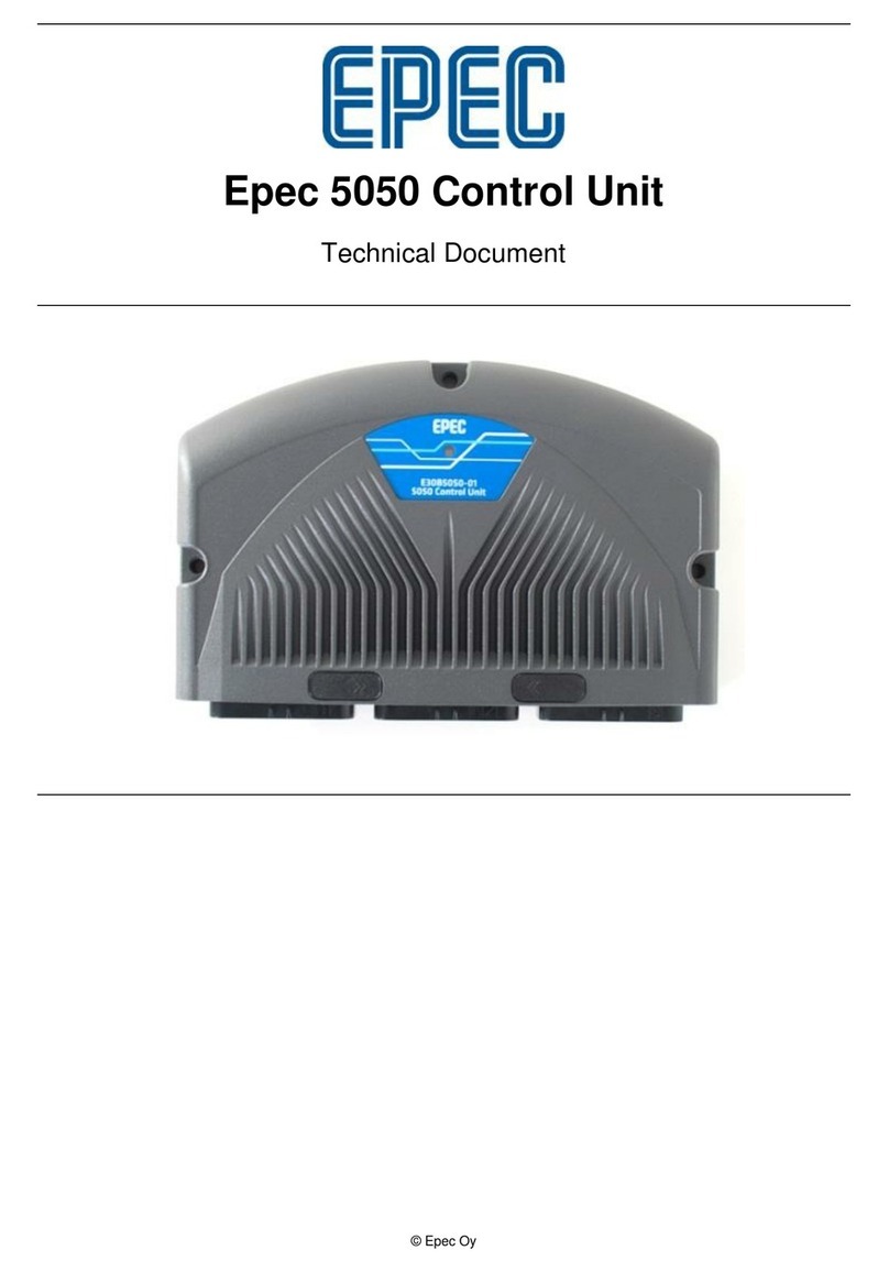
Epec 5050 Control Unit
Technical Document

Document version history
Date Notes
08.02.2013
Added Section Configurable I/Os
07.01.2013
Document updated (added 8 MByte hardware version)
04.12.2012
Document updated
19.10.2012
First release

Technical Manual 5050 / MAN000539
Epec Oy reserves all rights for improvements without prior notice
Epec Oy Postiosoite/Postal address Puhelin/Phone Fax Internet
Tiedekatu 6 PL/P.O.Box 194 +358-(0)20-7608 111 +358-(0)20-7608 110 www.epec.fi
FIN-60320 Seinäjoki FIN-60101 Seinäjoki, Finland
Table of Contents
1PREFACE.............................................................................................................................5
1.1 Use of Symbols.........................................................................................................5
1.2 Basic Skills Required ................................................................................................5
1.3 Safety Guidelines......................................................................................................6
1.4 Warranty....................................................................................................................6
1.5 Limited Liability..........................................................................................................7
1.6 Environmental Statement..........................................................................................7
1.6.1 WEEE..............................................................................................................7
1.6.2 RoHS...............................................................................................................7
2PRODUCT OVERVIEW........................................................................................................8
3TECHNICAL DATA ............................................................................................................10
4INPUT / OUTPUT SPECIFICATIONS................................................................................12
4.1 I/O List.....................................................................................................................12
4.2 Configurable I/Os ....................................................................................................15
4.3 PWM Output / Digital Output / Digital Input.............................................................16
4.3.1 PWM/DO/DI_Type005..................................................................................16
4.3.2 PWM/DO/DI_Type006..................................................................................18
4.3.3 PWM/DO/DI/CM_Type007 ...........................................................................21
4.3.4 PWM/DO/DI/CM_Type008 ...........................................................................24
4.4 Digital Input / Pulse Input........................................................................................27
4.4.1 DI/PI_Type001..............................................................................................27
4.4.2 DI/PI_Type002..............................................................................................29
4.4.3 DI/PI_Type003..............................................................................................30
4.4.4 Software Channels for Pulse Inputs .............................................................32
4.5 Analog Input / Digital Input......................................................................................33
4.5.1 AI/DI_Type011..............................................................................................33
4.6 Digital Output / GND ...............................................................................................35
4.6.1 DO_GND/DI_Type010..................................................................................35
4.7 Reference voltage supply pins................................................................................37
4.7.1 +5V REF_Type015 .......................................................................................37
4.7.2 +10 V REF_Type004 ....................................................................................38
4.8 Power supply pins and limitations...........................................................................39
4.9 Connection Examples .............................................................................................42
4.9.1 Connection Examples for DI/PI_Type001.....................................................43
4.9.2 Connection Examples for DI/PI_Type002.....................................................45
4.9.3 Connection Examples for DI/PI_Type003.....................................................46
4.9.4 Connection Examples for PWM/DO/DI_Type005.........................................48
4.9.5 Connection Examples for PWM/DO/DI_Type006.........................................50
4.9.6 Connection Examples for PWM/DO/DI/CM_Type007..................................52
4.9.7 Connection Examples for PWM/DO/DI/CM/Type008...................................54
4.9.8 Connection Examples for AI/DI_Type011.....................................................56
5BUS CONNECTIONS.........................................................................................................58
5.1 CAN bus..................................................................................................................58
5.2 Ethernet interface....................................................................................................59
6INTERNAL DIAGNOSTICS................................................................................................60
6.1 LED Indicator...........................................................................................................60
6.2 Temperature............................................................................................................61
6.3 Error Log .................................................................................................................61
7APPROVALS AND SAFETY..............................................................................................62
7.1 EMC Tests...............................................................................................................62

Technical Manual 5050 / MAN000539
Epec Oy reserves all rights for improvements without prior notice
Epec Oy Postiosoite/Postal address Puhelin/Phone Fax Internet
Tiedekatu 6 PL/P.O.Box 194 +358-(0)20-7608 111 +358-(0)20-7608 110 www.epec.fi
FIN-60320 Seinäjoki FIN-60101 Seinäjoki, Finland
7.2 Environmental Tests ...............................................................................................68
8MECHANICS AND CABLING............................................................................................70
8.1 Unit Dimensions......................................................................................................70
8.2 Mounting and Cleaning ...........................................................................................71
8.3 Plugging and unplugging the cables/connectors ....................................................73
8.4 Cabling ....................................................................................................................75
8.4.1 System Topologies .......................................................................................75
8.4.2 CAN Bus .......................................................................................................77
8.4.3 Ethernet ........................................................................................................79
8.4.4 I/O Cabling....................................................................................................80
8.4.5 Power supply ................................................................................................85
8.5 Welding ...................................................................................................................88
8.6 System Examples ...................................................................................................89
8.7 Accessories and Ordering Codes ...........................................................................91

Technical Manual 5050 / MAN000539
Epec Oy reserves all rights for improvements without prior notice
Epec Oy Postiosoite/Postal address Puhelin/Phone Fax Internet
Tiedekatu 6 PL/P.O.Box 194 +358-(0)20-7608 111 +358-(0)20-7608 110 www.epec.fi
FIN-60320 Seinäjoki FIN-60101 Seinäjoki, Finland
1 PREFACE
1.1 Use of Symbols
This manual uses the following symbols to point out important information or safety instructions:
The information icon indicates important information and issues to be noted for the
reader.
The caution icon indicates very important information or a warning. If the advices
are ignored, it can result in personal injury or damage to software or equipment.
The (electrical) warning icon indicates a hazard which could cause an electrical
danger and/or a personal injury.
CE compatibility
This symbol indicates that the product described in this manual complies with the
requirements set in the CE Standard.
WEEE symbol
This symbol indicates that the product must be sent to separate collection facilities
for recovery and recycling when the end-user wishes to discard the product.
E17 Approval
This product is certified with normal automotive (E17) EMC (electromagnetic
compatibility) standards.
1.2 Basic Skills Required
The user of this document must have basic knowledge of machine controlling, CAN
communication, PLCopen programming according to IEC61131-1 and should have skills to use
CODESYS 2.3 programming environment.
Please refer to CODESYS 2.3 manual for further information concerning the programming
environment and required installations.
Please refer to CAN and CANopen documentation from CAN in Automation (CiA) for further
information on communication issues.

Technical Manual 5050 / MAN000539 Page 6/92
Epec Oy reserves all rights for improvements without prior notice
Epec Oy Postiosoite/Postal address Puhelin/Phone Fax Internet
Tiedekatu 6 PL/P.O.Box 194 +358-(0)20-7608 111 +358-(0)20-7608 110 www.epec.fi
FIN-60320 Seinäjoki FIN-60101 Seinäjoki, Finland
1.3 Safety Guidelines
The user of this documentation should follow general machine safety guidelines, directives and
regulation appropriate to his/her country or market area.
A separate safety analysis is always recommended for the machine and its control system. The
features of this product should be well documented in machine and control system documents
so that the machine operator has the right information how to operate the machine correctly and
safely.
This product is designed to be used only for machine controlling purposes. The manufacturer
does not assume any responsibility for this product being fit for any particular application, unless
otherwise expressly stated in writing by the manufacturer.
This product complies with those certifications and standards that are listed below. The
manufacturer does not guarantee that this product complies any other certification, standard or
test than listed below.
This product is not field serviceable, so it should not be opened at any situation.
External fuses should be installed for the product or the system power supply.
The system should be designed and constructed according to the Epec general mounting and
cabling instruction document.
Epec Oy reserves a right to improve its products without a further notice.
1.4 Warranty
The manufacturer does not assume any responsibility for the products being fit for any particular
purpose, unless otherwise expressly stated in writing by the manufacturer.
The manufacturer gives the warranty of twelve (12) months to the products and thereto related
firmware from commissioning or eighteen (18) months from the date of delivery of the products
which ever occurs first.
The manufacturer is during the warranty period responsible for defects in the products and
thereto related firmware resulting from faults in material, design or workmanship. The
manufacturer’s only obligation under this warranty is to, at its sole discretion, either to replace
the products and/or thereto related firmware or to repair the defective products. The
manufacturer shall, at its sole option, repair the products at its manufactory in Seinäjoki,
Finland.
The warranty does not cover any costs related to removing or fastening of devices related to the
products. Neither does the warranty cover the expenses of sending devices to or from the
manufacturer for repairs. The warranty does not cover possible expenses relating to travelling,
accommodation, daily benefits, etc. of installers.
The warranty becomes null and void if the buyer and/or a third party alters the products or the
firmware in any way or if they are not used in accordance with the Manufacturer’s operating
instructions.
All claims with respect to defects in the products shall be made to the manufacturer without
delay and no later than on the seventh (7th) day after the defect has been or should have been
discovered by the buyer. The manufacturer strives to reply to the claim in writing within two (2)
weeks from the receipt of the claim. The buyer shall attach to the claim a possible error report or
equivalent explanation of the grounds for the claim.

Technical Manual 5050 / MAN000539 Page 7/92
Epec Oy reserves all rights for improvements without prior notice
Epec Oy Postiosoite/Postal address Puhelin/Phone Fax Internet
Tiedekatu 6 PL/P.O.Box 194 +358-(0)20-7608 111 +358-(0)20-7608 110 www.epec.fi
FIN-60320 Seinäjoki FIN-60101 Seinäjoki, Finland
The manufacturer gives no other warranties whatsoever for the products than the warranty set
out in this section and thus the warranty given in this section sets forth the warranty given by the
manufacturer in its entirety.
1.5 Limited Liability
The manufacturer shall under no circumstances be liable for loss of production, loss of profit,
loss of use or any other consequential damages and/or indirect losses, whatever their cause
may be. In case claims based on product liability are brought against the Manufacturer for which
claims the manufacturer may be liable, the manufacturer’s liability is limited to the extent
normally covered under normal product liability insurances.
The buyer shall compensate the manufacturer to the extent that the manufacturer might be
liable to pay damages as a result of claims based on product liability according to paragraph
above.
1.6 Environmental Statement
The manufacturer uses ISO14001 environmental certified processes and materials to
manufacture products. The manufacturer undertakes to arrange for the recycling and scrapping
of the products that are returned to the manufacturer by the buyer and/or the products that are
received by the Manufacturer in connection with maintenance services performed as a result of
that repairing of the products is deemed by the manufacturer to be inappropriate.
The manufacturer will charge a scrapping fee from the buyer according to the manufacturer's
price list in force from time to time. No scrapping fee will, however, be charged for products that
are received by the manufacturer during the warranty period.
1.6.1 WEEE
This product complies with the European Community Directive 2002/96/EC on waste electrical
and electronic equipment (WEEE) encouraging and setting specific criteria for the collection,
handling and recycling of electric and electronic waste.
1.6.2 RoHS
This product complies with the European Community directive 2011/65/EU (RoHS) restricting
hazardous substances such as quicksilver and lead in electrical and electronic equipment.

Technical Manual 5050 / MAN000539 Page 8/92
Epec Oy reserves all rights for improvements without prior notice
Epec Oy Postiosoite/Postal address Puhelin/Phone Fax Internet
Tiedekatu 6 PL/P.O.Box 194 +358-(0)20-7608 111 +358-(0)20-7608 110 www.epec.fi
FIN-60320 Seinäjoki FIN-60101 Seinäjoki, Finland
2 PRODUCT OVERVIEW
Epec 5050 Control Unit is a compact, powerful and robust multifunction controller with 32-bit
processor and efficient calculating power. Epec 5000 product platform is fully compatible to the
existing Epec product portfolio. Some of the advances of the Epec 5050 Control Unit are listed
below.
Multifunctional Efficiency
•A powerful multifunction controller
•32-bit processor
•increased calculating power
•floating point calculation
•Can be used used in a CAN control unit system as a multifunction controller with
different kinds of sensors and actuators, such as
•proportional valves,
•servo motors, and
•electro-hydraulic components
•Provides control system solutions for both centralized and distributed intelligence
systems
•Fully compatible with the existing Epec product portfolio
Mechanics & hardware
•Robust, light and leak proof aluminum/plastic cover has been widely tested against
different chemicals and environmental conditions
•The shape of the casing works to protect the electronics inside against mechanical
wear.
•Three point anchorage confirms firm mounting also on irregular surfaces
•Signal LED for quick status check and fault detection
•Equipped with gold plated, heavy duty AMPSEAL connectors
•Each connector is color coded and mechanically keyed to fit only to the correct,
corresponding place
•One CAN is equipped with double pins, which makes cabling easier since there is no
need for branches in the wire harness.
•Made in Finland

Technical Manual 5050 / MAN000539 Page 9/92
Epec Oy reserves all rights for improvements without prior notice
Epec Oy Postiosoite/Postal address Puhelin/Phone Fax Internet
Tiedekatu 6 PL/P.O.Box 194 +358-(0)20-7608 111 +358-(0)20-7608 110 www.epec.fi
FIN-60320 Seinäjoki FIN-60101 Seinäjoki, Finland
Versatile I/O capabilities
•Total of 65 I/O pins
•Most pins have multipurpose features
•All the I/O pins are equipped with a short-circuit protection
•Pulse inputs have a threshold voltage selection
•PWM outputs have a high side current measurement
•Some pins with an input feature have a programmable pull up / pull down selection
Application programming
•Application downloading is possible through both CAN bus and Ethernet
•Floating point calculation makes programming more efficient
•Epec products are based on PLCopen and CANopen®, which make them easily
scalable to meet the requirements for both small and large machines
•Open I/O and communication interface, thus making it possible to connect
•sensors
•actuators
•joysticks
•other devices
from other manufacturers to optimize the whole machine environment, both technically
and ergonomically.
•Internal error logging which makes it possible to
•save e.g. overvoltage and overtemperature alarms
•program customized log applications

Technical Manual 5050 / MAN000539 Page 10/92
Epec Oy reserves all rights for improvements without prior notice
Epec Oy Postiosoite/Postal address Puhelin/Phone Fax Internet
Tiedekatu 6 PL/P.O.Box 194 +358-(0)20-7608 111 +358-(0)20-7608 110 www.epec.fi
FIN-60320 Seinäjoki FIN-60101 Seinäjoki, Finland
3 TECHNICAL DATA
Processor 32-bit CPU, 128 MHz
Memory 4 MByte hardware version:
Flash 8 MByte
RAM 4 MByte (1 MByte for PLCopen application)
NVRAM 512 kbyte (for error logs, system parameters)
8 MByte hardware version:
Flash 8 MByte
RAM 8 MByte (3 MByte for PLCopen application)
NVRAM 512 kbyte (for error logs, system parameters)
Power Nominal supply voltage 12/24 VDC systems (8,3 ... 36 VDC),
Idle power consumption 2,2 W
Undervoltage reset 7,5 VControl unit shut down voltage typical 43 V
Overvoltage protection from 43 to 97,5 V
REF voltage outputs +5 V, +10 V
Diagnostics Signal LED (green/red)
Temperature monitoring
Error logging
Programming CODESYS 2.3, Application size 1 MByte (in 4MByte hardware version)
CODESYS 2.3, Application size 3 MByte (in 8MByte hardware version)
Software installation Download to flash memory via CAN1 or Ethernet
Protection class IP67
Size / Outer dimensions 224,8 x 148,5 x 50 mm
8.819 x 5.827 x 1.969 in
Weight 0,95 kg
2.09 lbs
Case material Aluminum / plastic
Operating temperature -40... +85°C
-40...+185°F
Storage temperature -40... +85°C
-40...+185°F
Connectors 3 x AMP35 (connector 1 grey, connector 2 black, connector 3 blue)

Technical Manual 5050 / MAN000539 Page 11/92
Epec Oy reserves all rights for improvements without prior notice
Epec Oy Postiosoite/Postal address Puhelin/Phone Fax Internet
Tiedekatu 6 PL/P.O.Box 194 +358-(0)20-7608 111 +358-(0)20-7608 110 www.epec.fi
FIN-60320 Seinäjoki FIN-60101 Seinäjoki, Finland
Communications/ Interfaces 4 x CAN 2.0 B,
1 x Ethernet
I/O pins total 65
Outputs 12 PWM/DO/DI with high side current measurement up to
2,5 A, PWM frequency adjustable by application
8 PWM/DO/DI with high side current measurement up to
2,5 A, voltage measurement, PWM frequency by application
4 PWM/DO/DI up to 2,5 A, PWM frequency by application,
pull-up / pull-down selection by application
4 PWM/DO/DI up to 4 A, PWM frequency by application,
pull-up / pull-down selection by application
4
DO/DI sinking up to 3 A
Inputs 11 DI/AI 0-10 V / 0-22 mA selection by application,
pull-up/ pull-down selection by application
12 bit AD converter
4 DI/PI 5/10 V, threshold selection by application,
pull-up/pull-down selection by application
14
DI/PI pull-up/pull-down selection by application
4
DI/PI pull-down to GND

Technical Manual 5050 / MAN000539 Page 12/92
Epec Oy reserves all rights for improvements without prior notice
Epec Oy Postiosoite/Postal address Puhelin/Phone Fax Internet
Tiedekatu 6 PL/P.O.Box 194 +358-(0)20-7608 111 +358-(0)20-7608 110 www.epec.fi
FIN-60320 Seinäjoki FIN-60101 Seinäjoki, Finland
4 INPUT / OUTPUT SPECIFICATIONS
4.1 I/O List
The three connectors are placed in the module according to the following figure:
The following table lists the pins according to their pin number. Other columns offer quick
information about the pin and links for more information.
The group column:
* P1/P2 indicates the power source for the pin
smaller case characters indicate the input groups (the pins in the same group have the
same configurations)
UPPER CASE CHARACTERS indicate the output groups (the pins in the same group have
the same configurations)
I/O table
Pin
number
Pin type Details Group* Current /
Voltage
Information
X1.1 LOGIC GND
X1.2 CAN4H
X1.3 CAN3H
X1.4 CAN2H
X1.5 CAN1H
X1.6 CAN1H
X1.7 CAN1H TERMINATOR
X1.8 REF +10V_Type004 +10 V 250 mA
X1.9 AI/DI_Type011
2,2 kΩ +10 V / 220 Ω GND
/ 47,5 kΩ GND
0..22 mA 0..10 V
X1.10 AI/DI_Type011
2,2 kΩ +10 V / 220 Ω GND
/ 47,5 kΩ GND
0..22 mA 0..10 V
X1.11 DI/PI_Type003
2,2 kΩ +10 V / 12,4 kΩ GND
a
Min input freq.
configurable
X1.12 PWM/DO/DI/CM_Type007 12,4 kΩ GND
P1 / N Nominal current 2,5 A
X1.13 LOADER BSL For factory use only
X1.14 CAN4L
X1.15 CAN3L
X1.16 CAN2L

Technical Manual 5050 / MAN000539 Page 13/92
Epec Oy reserves all rights for improvements without prior notice
Epec Oy Postiosoite/Postal address Puhelin/Phone Fax Internet
Tiedekatu 6 PL/P.O.Box 194 +358-(0)20-7608 111 +358-(0)20-7608 110 www.epec.fi
FIN-60320 Seinäjoki FIN-60101 Seinäjoki, Finland
X1.17 CAN1L
X1.18 CAN1L
X1.19 CAN1L TERMINATOR
X1.20 AI/DI_Type011
2,2 kΩ +10 V / 220 ΩGND
/ 47,5 kΩ GND
0..22 mA 0..10 V
X1.21 AI/DI_Type011
2,2 kΩ +10 V / 220 ΩGND
/ 47,5 kΩ GND
0..22 mA 0..10 V
X1.22 PWM/DO/DI_Type005
2,2 kΩ +10 V / 12,4 kΩ GND
P1 / B Nominal current 4 A
X1.23 PWM/DO/DI/CM_Type007
12,4 kΩ GND
P1 / N Nominal current 2,5 A
X1.24 Logic Power Supply
X1.25 ETHERNET TD+
X1.26 ETHERNET TD-
X1.27 ETHERNET RD+
X1.28 ETHERNET RD-
X1.29 PWM/DO/DI_Type006 2,2 kΩ +10 V / 12,4 kΩ GND P1 / C Nominal current 2,5 A
X1.30 PWM/DO/DI_Type006 2,2 kΩ +10 V / 12,4 kΩ GND P1 / C Nominal current 2,5 A
X1.31 PWM/DO/DI_Type006 2,2 kΩ +10 V / 12,4 kΩ GND P1 / D Nominal current 2,5 A
X1.32 PWM/DO/DI_Type006 2,2 kΩ +10 V / 12,4 kΩ GND P1 / D Nominal current 2,5 A
X1.33 PWM/DO/DI_Type005 2,2 kΩ +10 V / 12,4 kΩ GND P1 / E Nominal current 4 A
X1.34 PWM/DO/DI_Type005 2,2 kΩ +10 V / 12,4 kΩ GND P1 / E Nominal current 4 A
X1.35 PWM/DO/DI_Type005 2,2 kΩ +10 V / 12,4 kΩ GND P1 / B Nominal current 4 A
X2.1 Power1 GND
X2.2 Power1 GND
X2.3 GND
X2.4 REF +10V_Type004 +10 V 250 mA
X2.5 REF +5V_Type015 +5 V 350 mA
X2.6 DI/PI_Type001 2,2 kΩ +10 V / 12,4 kΩ GND f Thresh. 5 /10 V
X2.7 DI/PI_Type001 2,2 kΩ +10 V / 12,4 kΩ GND f Thresh. 5 /10 V
X2.8 DI/PI_Type001 2,2 kΩ +10 V / 12,4 kΩ GND g Thresh. 5 /10 V
X2.9 DI/PI_Type001 2,2 kΩ +10 V / 12,4 kΩ GND g Thresh. 5 /10 V
X2.10 GND
X2.11 GND
X2.12 GND
X2.13 PWM/DO/DI/CM_Type007 12,4 kΩ GND P1 / Q Nominal current 2,5 A
X2.14 PWM/DO/DI/CM_Type007 12,4 kΩ GND P1 / Q Nominal current 2,5 A
X2.15 DI/PI_Type002 12,4 kΩ GND
X2.16 DI/PI_Type003 2,2 kΩ +10 V / 12,4 kΩ GND h
X2.17 DI/PI_Type003 2,2 kΩ +10 V / 12,4 kΩ GND h
X2.18 DI/PI_Type002 12,4 kΩ GND
X2.19 DI/PI_Type003 2,2 kΩ +10 V / 12,4 kΩ GND i
X2.20 DI/PI_Type003 2,2 kΩ +10 V / 12,4 kΩ GND i
X2.21 Reserved For factory use only 0/4..20 mA
X2.22 Reserved For factory use only 0/4..20 mA

Technical Manual 5050 / MAN000539 Page 14/92
Epec Oy reserves all rights for improvements without prior notice
Epec Oy Postiosoite/Postal address Puhelin/Phone Fax Internet
Tiedekatu 6 PL/P.O.Box 194 +358-(0)20-7608 111 +358-(0)20-7608 110 www.epec.fi
FIN-60320 Seinäjoki FIN-60101 Seinäjoki, Finland
X2.23 AI/DI_Type011
2,2 kΩ +10 V / 220 ΩGND
/ 47,5 kΩ GND
0/4..20 mA 0..10 V
X2.24 Power1 Supply
X2.25 Power1 Supply
X2.26 DO_GNDType010 12,4 kΩ GND P1 Nominal current 3 A
X2.27 DO_GNDType010 12,4 kΩ GND P1 Nominal current 3 A
X2.28 PWM/DO/DI/CM_Type007 12,4 kΩ GND P2 / O Nominal current 2,5 A
X2.29 PWM/DO/DI/CM_Type007 12,4 kΩ GND P2 / O Nominal current 2,5 A
X2.30 PWM/DO/DI/CM_Type007 12,4 kΩ GND P2 / R Nominal current 2,5 A
X2.31 PWM/DO/DI/CM_Type007 12,4 kΩ GND P2 / R Nominal current 2,5 A
X2.32 PWM/DO/DI/CM_Type007 12,4 kΩ GND P2 / T Nominal current 2,5 A
X2.33 PWM/DO/DI/CM_Type007 12,4 kΩ GND P2 / T Nominal current 2,5 A
X2.34 DO_GNDType010 12,4 kΩ GND P1 Nominal current 3 A
X2.35 DO_GNDType010 12,4 kΩ GND P1 Nominal current 3 A
X3.1 Power2 GND
X3.2 Power2 GND
X3.3 GND
X3.4 GND
X3.5 DI/PI_Type003 2,2 kΩ +10 V / 12,4 kΩ GND j Min input freq.
configurable
X3.6 DI/PI_Type003 2,2 kΩ +10 V / 12,4 kΩ GND j Min input freq.
configurable
X3.7 DI/PI_Type002 12,4 kΩ GND
X3.8 DI/PI_Type003 2,2 kΩ +10 V / 12,4 kΩ GND k Min input freq.
configurable
X3.9 DI/PI_Type003 2,2 kΩ +10 V / 12,4 kΩ GND k Min input freq.
configurable
X3.10 DI/PI_Type002 12,4 kΩ GND
X3.11 DI/PI_Type003 2,2 kΩ +10 V / 12,4 kΩ GND l Min input freq.
configurable
X3.12 DI/PI_Type003 2,2 kΩ +10 V / 12,4 kΩ GND l Min input freq.
configurable
X3.13 REF +10V_Type004 +10 V 250 mA
X3.14 AI/DI_Type011
2,2 kΩ +10 V / 220 ΩGND
/ 47,5 kΩ GND
0..22 mA 0..10 V
X3.15 AI/DI_Type011
2,2 kΩ +10 V / 220 ΩGND
/ 47,5 kΩ GND
0..22 mA 0..10 V
X3.16 AI/DI_Type011
2,2 kΩ +10 V / 220 ΩGND
/ 47,5 kΩ GND
0..22 mA 0..10 V
X3.17 AI/DI_Type011
2,2 kΩ +10 V / 220 ΩGND
/ 47,5 kΩ GND
0..22 mA 0..10 V
X3.18 AI/DI_Type011
2,2 kΩ +10 V / 220 ΩGND
/ 47,5 kΩ GND
0..22 mA 0..10 V
X3.19 AI/DI_Type011
2,2 kΩ +10 V / 220 ΩGND
/ 47,5 kΩ GND 0..22 mA 0..10 V
X3.20 REF +5V_Type015 +5 V 350 mA
X3.21 DI/PI_Type003 2,2 kΩ +10 V / 12,4 kΩ GND m Min input freq.
configurable
X3.22 DI/PI_Type003 2,2 kΩ +10 V / 12,4 kΩ GND m Min input freq.
configurable

Technical Manual 5050 / MAN000539 Page 15/92
Epec Oy reserves all rights for improvements without prior notice
Epec Oy Postiosoite/Postal address Puhelin/Phone Fax Internet
Tiedekatu 6 PL/P.O.Box 194 +358-(0)20-7608 111 +358-(0)20-7608 110 www.epec.fi
FIN-60320 Seinäjoki FIN-60101 Seinäjoki, Finland
X3.23 DI/PI_Type003 2,2 kΩ +10 V / 12,4 kΩ GND a Min input freq.
configurable
X3.24 Power2 Supply
X3.25 Power2 Supply
X3.26 PWM/DO/DI/CM_Type007 12,4 kΩ GND P2 / S Nominal current 2,5 A
X3.27 PWM/DO/DI/CM_Type007 12,4 kΩ GND P2 / S Nominal current 2,5 A
X3.28 PWM/DO/DI/CM_Type008 12,4 kΩ GND P2 / U Nominal current 2,5 A
X3.29 PWM/DO/DI/CM_Type008 12,4 kΩ GND P2 / U Nominal current 2,5 A
X3.30 PWM/DO/DI/CM_Type008 12,4 kΩ GND P2 / X Nominal current 2,5 A
X3.31 PWM/DO/DI/CM_Type008 12,4 kΩ GND P2 / X Nominal current 2,5 A
X3.32 PWM/DO/DI/CM_Type008 12,4 kΩ GND P2 / V Nominal current 2,5 A
X3.33 PWM/DO/DI/CM_Type008 12,4 kΩ GND P2 / V Nominal current 2,5 A
X3.34 PWM/DO/DI/CM_Type008 12,4 kΩ GND P2 / Y Nominal current 2,5 A
X3.35 PWM/DO/DI/CM_Type008 12,4 kΩ GND P2 / Y Nominal current 2,5 A
4.2 Configurable I/Os
Control unit contains inputs and outputs or, in other words, I/O pins of many different types.
There are, for example, outputs which source current and outputs which sink current.
Furthermore, there are I/O pins which can be used as inputs or as outputs at the control of the
application programmer.
The following table contains a summary of configurable I/O pins in Epec 5050 control unit:
Max
Amount
Pin Type Info DI AI Current
Measurement
Voltage
Measurement
PI DO PWM
PNP
NPN
12
PWM/DO/DI/CM_Type007
2,5A
x
x
x
x
8
PWM/DO/DI/CM_Type008
2,5A
x
x
x
x
x
4
PWM/DO/DI_Type006
2,5A
x
x
x
4
PWM/DO/DI_Type005
4A
x
x
x
4
DO_GND_Type010
3A
x
x
11 AI/DI_Type011 0-10 V /
0-22 mA
x x
4 DI/PI_Type001 5/10 V
pull-up/
pull-down
x x
14 DI/PI_Type003 pull-up/
pull-down
x x
4
DI/PI_Type002
pull-down
x
x

Technical Manual 5050 / MAN000539 Page 16/92
Epec Oy reserves all rights for improvements without prior notice
Epec Oy Postiosoite/Postal address Puhelin/Phone Fax Internet
Tiedekatu 6 PL/P.O.Box 194 +358-(0)20-7608 111 +358-(0)20-7608 110 www.epec.fi
FIN-60320 Seinäjoki FIN-60101 Seinäjoki, Finland
4.3 PWM Output / Digital Output / Digital Input
This product has four different types of PWM/DO/DI pins. The following table shows their
differences:
Pin type Pull-up
selection 2,5
A 4 A Current
Measurement Voltage
Measurement
PWM/DO/DI_Type005
X
X
PWM/DO/DI_Type006
X
X
PWM/DO/DI/CM_Type007
X
X
PWM/DO/DI/CM_Type008
X
X
X
4.3.1 PWM/DO/DI_Type005
Output (PWM/DO)
•This kind of pin is a current sourcing output with a pull-up selection
•In other words, the pin connects the load to a positive supply voltage
•When the pull-up is selected, it will affect two output pins (the pairs are indicated with upper
case characters in the pin table's Group column in section Pinout Map).
•This pull-up feature is for open load detection when the pin is used as an output.
•These outputs have a switching element called a smart FET. It has integrated features to
protect itself and also the external pin, wiring and actuator.
•These outputs are capable of generating pulse width modulated (PWM) output signals.
•When used as an output, the input feature indicates the output FET's state
Before the supply voltage can be connected to an output pin, the related power
switch must be switched on as well.
Input (DI)
•This pin can be used as a digital input (DI)
•A pin of this type can also be used as an input by using the output state monitoring feature.
•In this case, the output functionality of the pin must be kept in the off state.
•It must be taken care in system design that the output unintentionally switching to on state
causes no harm to the system.
•This pin can be used also with NPN-type sensors – sensors with open collector/open drain.
Electrical characteristics
Symbol Parameter Conditions Min Max Units
VLevel Output voltage Output Off, Pull-up selected,
Unconnected pin typ. 8,3 V
IoNominal Output Current
Output On
(Note 7)
0 4 A

Technical Manual 5050 / MAN000539 Page 17/92
Epec Oy reserves all rights for improvements without prior notice
Epec Oy Postiosoite/Postal address Puhelin/Phone Fax Internet
Tiedekatu 6 PL/P.O.Box 194 +358-(0)20-7608 111 +358-(0)20-7608 110 www.epec.fi
FIN-60320 Seinäjoki FIN-60101 Seinäjoki, Finland
Io-lim Internal current limitation Output On (Note 5, 9) typ. 8 A
fPWM PWM Frequency (Note 1) 10 3000 Hz
DutyPWM PWM
Duty cycle (Note 2, 10) 0 to 100 %
ResPWM PWM Resolution (Note 3) 0,1 %
Digital status input
RIInput Resistance Output Off, Pull-up resistor
not selected
typ. 12 kΩ
VIH Digital status input
High Voltage level Output Off (Note6) 3,2 V
VIL Digital status input
Input Low Voltage Output Off 1,9 V
VI-range Input voltage range (Note 11) -0,5 Uin +
0,2V
V
tIDigital Status Input
Pulse Width
(Note 2, 4, 8) > tC ms
CIInput pin capacitance typ. 1 nF
Note 1: The frequency of a (PWM) Pulse Width Modulation is = 1 / Period
Note 2: The duty cycle is defined as the percentage of digital ‘high’ to digital ‘low’ signals
present during a PWM period.
Note 3: The PWM resolution is defined as the maximum number of pulses that you can pack
into a PWM period.
Note 4: tC denotes the software cycle time.
Note 5: Current limit for short circuit protection to protect cabling and to limit internal power
dissipation.
Note 6: Exceeding the max value might cause damage to input.
Note 7: The maximum output current depends on the load, PWM frequency and temperature.
Note 8: The pulse width must be greater that the software cycle time. For example with 50/50
pulse ratio, the pulse frequency is 1 / (2*pulse width)
Note 9: When the limit is exceeded, the output voltage circuit starts to limit the current by
switching the output voltage. The switching does not effect the application software
Note 10: When the frequency increases, the actual duty cycle may be bigger than the value that
has been set.
Note 11: Overload conditions

Technical Manual 5050 / MAN000539 Page 18/92
Epec Oy reserves all rights for improvements without prior notice
Epec Oy Postiosoite/Postal address Puhelin/Phone Fax Internet
Tiedekatu 6 PL/P.O.Box 194 +358-(0)20-7608 111 +358-(0)20-7608 110 www.epec.fi
FIN-60320 Seinäjoki FIN-60101 Seinäjoki, Finland
Functional block diagram
Refer to section Connection Examples to see examples of how to connect external
actuators or sensors when using this type of pin.
4.3.2 PWM/DO/DI_Type006
Output (PWM/DO)
•This kind of pin is a current sourcing output with a pull-up selection
•In other words, the pin connects the load to a positive supply voltage.
•When the pull-up is selected, it will affect two output pins (the pairs are indicated with upper
case characters in the pin table's Group column in section Pinout Map).
•This pull-up feature is for open load detection when the pin is used as an output.
•These outputs have a switching element called a smart FET. It has integrated features to
protect itself and also the external pin, wiring and actuator.
•These outputs are capable of generating pulse width modulated (PWM) output signals.
•When used as an output, the input feature indicates the output FET's state
Before the supply voltage can be connected to an output pin, the related power
switch must be switched on as well.

Technical Manual 5050 / MAN000539 Page 19/92
Epec Oy reserves all rights for improvements without prior notice
Epec Oy Postiosoite/Postal address Puhelin/Phone Fax Internet
Tiedekatu 6 PL/P.O.Box 194 +358-(0)20-7608 111 +358-(0)20-7608 110 www.epec.fi
FIN-60320 Seinäjoki FIN-60101 Seinäjoki, Finland
The FET outputs are grouped into pairs:
•The maximum continuous current for a single output in the pair is 2,5 A.
•The maximum continuous current for the pair is 4 A.
The pairs are indicated with upper case characters in the pin table's Group column
in section Pinout Map
Input (DI)
•This pin can be used as a digital input (DI)
•A pin of this type can also be used as an input by using the output state monitoring feature.
•In this case, the output functionality of the pin must be kept in the off state.
•It must be taken care in system design that the output unintentionally switching to on state
causes no harm to the system.
•This pin can be used also with NPN-type sensors – sensors with open collector/open drain.
Electrical characteristics
Symbol Parameter Conditions Min Max Units
VLevel Output voltage Output Off, Pull-up selected,
Unconnected pin
typ. 8,3 V
IoNominal Output Current Output On
(Note 7)
0 2,5 A
Io-lim
Internal current limitation
Output On (Note 5, 9)
typ. 8
A
fPWM
PWM Frequency
(Note 1)
10
3000
Hz
DutyPWM PWM
Duty cycle
(Note 2, 10) 0 to 100 %
ResPWM
PWM Resolution
(Note 3)
0,1
%
Digital status input
RIInput Resistance Output Off, Pull-up resistor
not selected
typ. 13 kΩ
VIH Digital status input
High Voltage level
Output Off (Note 6) 3,2 V
VIL Digital status input
Input Low Voltage
Output Off 1,9 V
VI-range Input voltage range (Note 11) -0,5 Uin +
0,2V
V
tIDigital Status Input
Pulse Width (Note 2, 4, 8)
> tC ms
CI
Input pin capacitance
typ. 1
nF
Note 1: Frequency of a (PWM) Pulse Width Modulation is = 1 / Period
Note 2: The duty cycle is defined as the percentage of digital ‘high’ to digital ‘low’ signals
present during a PWM period.
Note 3: The PWM resolution is defined as the maximum number of pulses that you can pack
into a PWM period.
Note 4: tC denotes software cycle time.
Note 5: Current limit for short circuit protection to protect cabling and to limit internal power
dissipation.
Note 6: Exceeding the max value might cause damage to input.
Note 7: The maximum output current depends on the load, PWM frequency and temperature.
Note 8: Pulse width must be greater that the software cycle time. For example with 50/50 pulse
ratio, the pulse frequency is 1 / (2*pulse width)

Technical Manual 5050 / MAN000539 Page 20/92
Epec Oy reserves all rights for improvements without prior notice
Epec Oy Postiosoite/Postal address Puhelin/Phone Fax Internet
Tiedekatu 6 PL/P.O.Box 194 +358-(0)20-7608 111 +358-(0)20-7608 110 www.epec.fi
FIN-60320 Seinäjoki FIN-60101 Seinäjoki, Finland
Note 9: When the limit is exceeded, the output voltage circuit starts to limit the current by
switching the output voltage. The switching does not affect the application software.
Note 10: When the frequency increases, the actual duty cycle may be bigger than the value that
has been set.
Note 11: Overload conditions
Functional block diagram
Refer to section Connection Examples to see examples of how to connect external
actuators or sensors when using this type of pin.
Other manuals for 5050
2
Table of contents
Other Epec Control Unit manuals
