HEIDENHAIN TNC 151 Q User manual
Other HEIDENHAIN Control Unit manuals
HEIDENHAIN
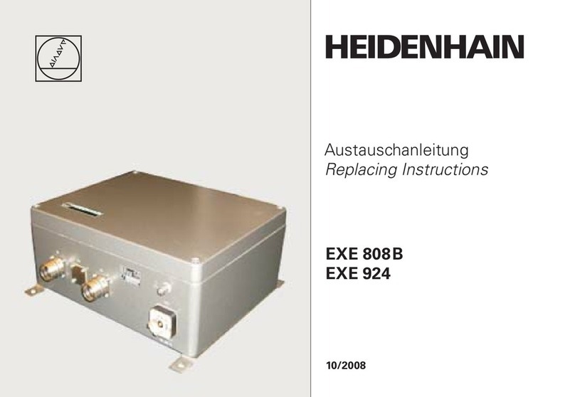
HEIDENHAIN EXE 808B User manual

HEIDENHAIN
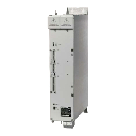
HEIDENHAIN TNC 620 Programming Station User manual
HEIDENHAIN
HEIDENHAIN UM 112D User manual

HEIDENHAIN
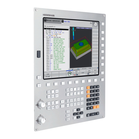
HEIDENHAIN TNC 620 Programming Station User manual
HEIDENHAIN
HEIDENHAIN TNC 320 Programming Station User manual

HEIDENHAIN
HEIDENHAIN ND 1200 QUADRA-CHEK User manual
HEIDENHAIN
HEIDENHAIN TNC 426 PB/M User manual

HEIDENHAIN
HEIDENHAIN TNC 620 User manual

HEIDENHAIN
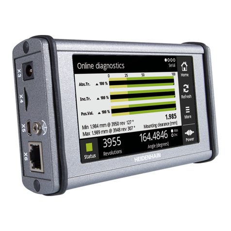
HEIDENHAIN TNC 320 Programming Station User manual
HEIDENHAIN
HEIDENHAIN PWT 101 User manual

HEIDENHAIN
HEIDENHAIN TNC 320 Programming Station User manual

HEIDENHAIN
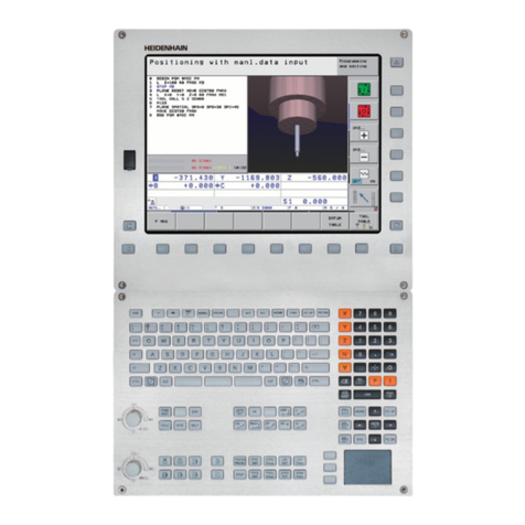
HEIDENHAIN ITNC 530 - CONVERSATIONAL PROGRAMMING User manual
HEIDENHAIN
HEIDENHAIN ITNC 530 - CONVERSATIONAL PROGRAMMING User manual
HEIDENHAIN
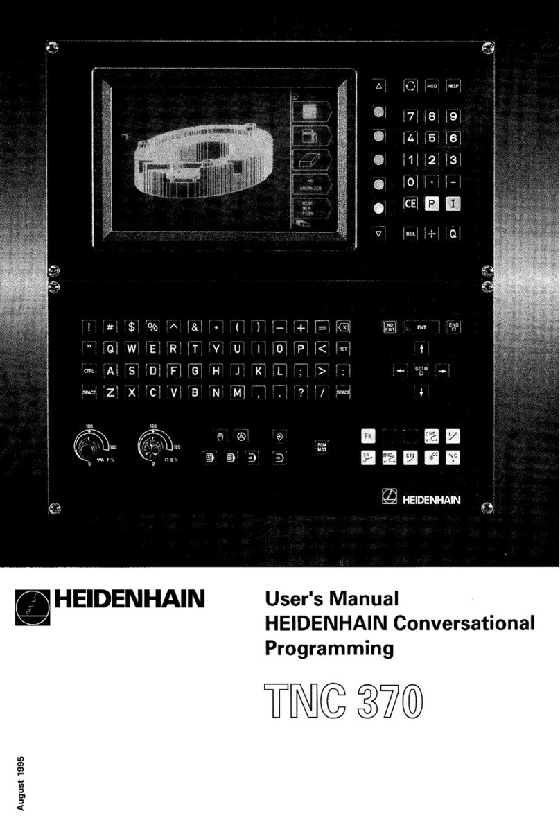
HEIDENHAIN TNC 370 User manual

HEIDENHAIN
HEIDENHAIN TNC 620 Programming Station User manual

HEIDENHAIN
HEIDENHAIN TNC 620 Programming Station User manual

HEIDENHAIN
HEIDENHAIN TNC 640 User manual

HEIDENHAIN
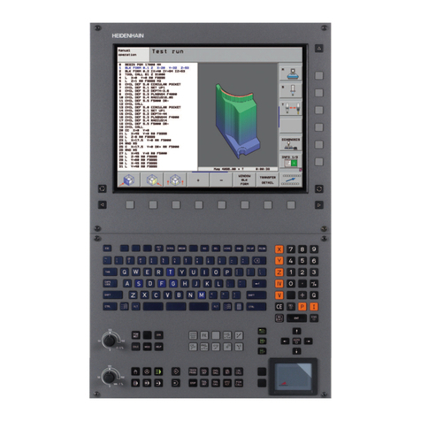
HEIDENHAIN TNC 320 User manual
HEIDENHAIN
HEIDENHAIN ITNC 530 - CONVERSATIONAL PROGRAMMING User manual
Popular Control Unit manuals by other brands

Festo
Festo Compact Performance CP-FB6-E Brief description

Elo TouchSystems
Elo TouchSystems DMS-SA19P-EXTME Quick installation guide

JS Automation
JS Automation MPC3034A user manual

JAUDT
JAUDT SW GII 6406 Series Translation of the original operating instructions

Spektrum
Spektrum Air Module System manual

BOC Edwards
BOC Edwards Q Series instruction manual

KHADAS
KHADAS BT Magic quick start

Etherma
Etherma eNEXHO-IL Assembly and operating instructions

PMFoundations
PMFoundations Attenuverter Assembly guide

GEA
GEA VARIVENT Operating instruction

Walther Systemtechnik
Walther Systemtechnik VMS-05 Assembly instructions

Altronix
Altronix LINQ8PD Installation and programming manual


