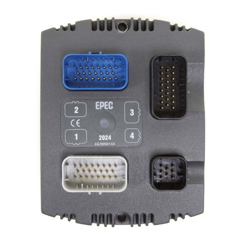
Epec 6200 User manual

© Epec Oy
Epec 6200 Control Unit
Technical Document
MAN000719
PUBLIC
Functional Versions
6200-222
6200-223
6200-268
6200-269
Document version history
Date
Notes
31.03.2022
Added: Functional Version 6200-222
23.11.2021
Preliminary Release
Added: Industry Canada Compliance Statement
30.03.2020
First released version

6200 Technical Manual
MAN000719
Page 2
PUBLIC
Epec Oy reserves all rights for improvements without prior notice
Epec Oy
Tiedekatu 6
FIN-60320 Seinäjoki
Postal address
PL/P.O.Box 194
FIN-60101 Seinäjoki, Finland
Phone
+358-(0)20-7608 111
Internet
www.epec.fi
Table of Contents
1PREFACE .............................................................................................................................4
1.1 Use of Symbols............................................................................................ 4
1.2 Basic Skills Required ................................................................................... 5
1.3 Safety Guidelines ........................................................................................ 5
1.4 Warranty .................................................................................................... 5
1.5 Limited Liability .......................................................................................... 6
1.6 Environmental Statement............................................................................ 6
2PRODUCT OVERVIEW ........................................................................................................7
3FUNCTIONAL VERSIONS ...................................................................................................8
4TECHNICAL DATA.............................................................................................................10
5CONNECTORS AND PIN ASSIGNMENTS .......................................................................12
6DO/DI...................................................................................................................................15
6.1 DO (digital output) mode........................................................................... 15
6.2 DI (digital input) mode .............................................................................. 15
6.3 Functional block diagram ......................................................................... 17
7AI/DI ....................................................................................................................................18
7.1 AI (Analog Input) mode ............................................................................. 18
7.2 DI (Digital Input) mode.............................................................................. 18
7.3 Functional block diagram ......................................................................... 20
8DI.........................................................................................................................................21
8.1 Functional block diagram ......................................................................... 22
9ACCELEROMETER (OPTION) ..........................................................................................23
10 +5 V REF.............................................................................................................................24
10.1 Protection features ................................................................................... 24
10.2 Voltage monitoring ................................................................................... 24
10.3 Functional block diagram ......................................................................... 25
11 POWER SUPPLY................................................................................................................26
11.1 Overvoltage Protection.............................................................................. 26
11.2 Power Consumption .................................................................................. 26
12 INTERFACES......................................................................................................................28
12.1 CAN Bus.................................................................................................... 28
12.1.1CAN bus connection pins ................................................................. 28
12.2 RS-232 ...................................................................................................... 30
12.3 USB ........................................................................................................... 31
12.4 Ethernet .................................................................................................... 32
12.5 Cellular GSM/UMTS/LTE ............................................................................ 33
12.6 WLAN ........................................................................................................ 35
12.7 GPS/GLONASS ........................................................................................... 36
12.8 LTE Diversity............................................................................................. 37
13 INTERNAL DIAGNOSTICS ................................................................................................38
13.1 Temperature and Voltage Monitoring ....................................................... 38
13.1.1Temperature Monitoring.................................................................. 38
13.1.2Supply Voltage Monitoring ............................................................... 38
13.2 LED Indicator ............................................................................................ 39
13.3 + 5 V REF Diagnostics ............................................................................... 41
13.3.1OVERLOAD....................................................................................... 41

6200 Technical Manual
MAN000719
Page 3
PUBLIC
Epec Oy reserves all rights for improvements without prior notice
Epec Oy
Tiedekatu 6
FIN-60320 Seinäjoki
Postal address
PL/P.O.Box 194
FIN-60101 Seinäjoki, Finland
Phone
+358-(0)20-7608 111
Internet
www.epec.fi
13.3.2OVERVOLTAGE................................................................................. 41
14 APPROVALS AND SAFETY..............................................................................................42
14.1 EMC Tests ................................................................................................. 42
14.2 RF Tests .................................................................................................... 43
14.3 Environmental Tests ................................................................................. 51
14.4 Simplified EU Declaration of Conformity ................................................... 52
14.4.1Frequency, mode and maximum transmitted power ........................ 52
14.4.2Country Limitations ......................................................................... 52
14.5 Industry Canada Compliance Statement ................................................... 53
Avis de conformité à la réglementation d'Industrie Canada ...................... 53
14.5.1Notice for Canada............................................................................ 53
14.5.2Canada Radiation Exposure Statement ............................................ 53
14.6 Supplier's Declaration of Conformity 47 CFR § 2.1077 Compliance
Information........................................................................................................ 54
14.6.1FCC Compliance Statement .............................................................. 54
15 MECHANICS AND CABLING ............................................................................................55
15.1 Unit Dimensions........................................................................................ 55
15.2 Mounting and Cleaning ............................................................................. 55
15.3 Plugging and unplugging the cables/connectors ....................................... 57
15.4 Cabling ..................................................................................................... 59
15.4.1System Topologies ........................................................................... 59
15.4.2CAN Bus Cabling.............................................................................. 61
15.4.3I/O Cabling ...................................................................................... 64
15.4.4Ethernet Cabling .............................................................................. 65
15.4.5RS-232 Cabling ................................................................................ 68
15.4.6USB Cabling ..................................................................................... 68
15.4.7Power Supply Cabling ...................................................................... 69
15.4.8Antenna Installation ........................................................................ 70
15.5 Welding..................................................................................................... 71
15.6 Accessories and Ordering Codes ............................................................... 72
15.6.1Related products.............................................................................. 72
15.6.2AMPSEAL Connectors ....................................................................... 74
15.6.3AMPSEAL cable dimensions .............................................................. 74
16 GLOSSARY ........................................................................................................................75

6200 Technical Manual
MAN000719
Page 4
PUBLIC
Epec Oy reserves all rights for improvements without prior notice
Epec Oy
Tiedekatu 6
FIN-60320 Seinäjoki
Postal address
PL/P.O.Box 194
FIN-60101 Seinäjoki, Finland
Phone
+358-(0)20-7608 111
Internet
www.epec.fi
1 PREFACE
1.1 Use of Symbols
This manual uses the following symbols to point out important information or safety
instructions:
The information icon indicates important information and issues to be
noted for the reader.
The caution icon indicates very important information or a warning. If the
advices are ignored, it can result in personal injury or damage to software
or equipment.
The (electrical) warning icon indicates a hazard which could cause an
electrical danger and/or a personal injury.
The following symbols may be used on Epec's product labels:
Caution, surface may be hot.
CE compatibility
This symbol indicates that the product complies with the
requirements set in the CE Standard.
WEEE symbol
This symbol indicates that the product must be sent to separate
collection facilities for recovery and recycling when the end-user
wishes to discard the product.
E17 Approval
This symbol indicates that the product is certified with normal
automotive (E17) EMC (electromagnetic compatibility) standards.
FCC Logo
FCC Logo Devices authorized under the SDoC procedure have the
option to use the FCC logo to indicate compliance with the FCC rules,
12 and the logo may be included in the instruction materials or as
part of an e-label.
RCM (Regulatory Compliance Mark)
This symbol indicates that the product complies with the ACMA
(Australian Communications and Media Authority) regulatory
arrangements concerning electromagnetic compatibility and radio
equipment.

6200 Technical Manual
MAN000719
Page 5
PUBLIC
Epec Oy reserves all rights for improvements without prior notice
Epec Oy
Tiedekatu 6
FIN-60320 Seinäjoki
Postal address
PL/P.O.Box 194
FIN-60101 Seinäjoki, Finland
Phone
+358-(0)20-7608 111
Internet
www.epec.fi
1.2 Basic Skills Required
The user of this document must have basic knowledge of machine controlling, CAN
communication, PLCopen programming according to IEC61131-3 and should have
skills to use CODESYS 3.5 programming environment.
Refer to CODESYS manual for further information concerning the programming
environment and required installations.
Refer to CAN and CANopen documentation from CAN in Automation (CiA) for further
information on communication issues.
1.3 Safety Guidelines
The user of this documentation should follow general machine safety guidelines,
directives and regulation appropriate to their country or market area.
A separate safety analysis is always recommended for the machine and its control
system. The features of this product should be well documented in machine and
control system documents so that the machine operator has the right information how
to operate the machine correctly and safely.
The manufacturer does not assume any responsibility for this product being fit for any
particular application, unless otherwise expressly stated in writing by the
manufacturer.
This product complies with those certifications and standards that are mentioned in
this manual. The manufacturer does not guarantee that this product complies with any
other certification, standard or test other than mentioned in this manual.
This product is not field serviceable, so it should not be opened in any situation.
External fuses should be installed for the product or the system power supply.
The system should be designed and constructed according to the Epec general
mounting and cabling instruction document.
Epec Oy reserves a right to improve its products without a further notice.
1.4 Warranty
Information concerning the warranty of this product can be found from Epec General
Sales and Warranty Terms.

6200 Technical Manual
MAN000719
Page 6
PUBLIC
Epec Oy reserves all rights for improvements without prior notice
Epec Oy
Tiedekatu 6
FIN-60320 Seinäjoki
Postal address
PL/P.O.Box 194
FIN-60101 Seinäjoki, Finland
Phone
+358-(0)20-7608 111
Internet
www.epec.fi
1.5 Limited Liability
The manufacturer shall under no circumstances be liable for loss of production, loss of
profit, loss of use or any other consequential damages and/or indirect losses, whatever
their cause may be. In case claims based on product liability are brought against the
Manufacturer for which claims the manufacturer may be liable, the manufacturer’s
liability is limited to the extent normally covered under normal product liability
insurances.
The buyer shall compensate the manufacturer to the extent that the manufacturer
might be liable to pay damages as a result of claims based on product liability
according to paragraph above.
1.6 Environmental Statement
The manufacturer has a certified ISO 14001: 2015 environmental management system
and certified processes to manufacture products. The manufacturer acts in an
environmentally responsible manner and always complies with valid environmental
legislation and directives .
The manufacturer is committed to comply with all relevant product regulations and
directives concerning product safety, and responsible sourcing of raw materials and
components. The position paper on REACH and RoHS compliance and Conflict Minerals
can be found from Epec Oy's website.
The manufacturer undertakes to arrange for the recycling and scrapping of products
that are returned to the manufacturer by the buyer and/or products that are received
by the manufacturer in connection with maintenance services and deemed unusable by
the manufacturer.
This product complies with the European Community Directive 2012/19/EU on waste
electrical and electronic equipment (WEEE) encouraging and setting specific criteria for
the collection, handling and recycling of electric and electronic waste. Outside of the
European Union, local guidelines for recycling shall be followed.
This product includes a lithium battery soldered on the PCB's bottom side
(placed on the upper right part of the PCB). When recycling the product,
make sure that the battery is removed from the PCB and recycled
separately.

6200 Technical Manual
MAN000719
Page 7
PUBLIC
Epec Oy reserves all rights for improvements without prior notice
Epec Oy
Tiedekatu 6
FIN-60320 Seinäjoki
Postal address
PL/P.O.Box 194
FIN-60101 Seinäjoki, Finland
Phone
+358-(0)20-7608 111
Internet
www.epec.fi
2 PRODUCT OVERVIEW
Epec 6200 Remote Access Unit (RAU) is a high-performance, programmable,
control and communication unit for mobile machines. Epec 6200 RAU has
multiple use cases such as data collection, communication gateway, remote
access or edge computing. Epec 6200 RAU is fully compatible with the existing
Epec control units and supports Epec GlobE remote management platform, Epec
GatE secure access solution, CODESYS 3.5 WebVisu functionality, Epec
MultiTool, Epec CANmoon and Epec PLCopen libraries.
Epec 6200 Remote Access Unit has some unique features listed below:
Processing power and connectivity
•Powerful Dual/Quad Core Cortex-A9 ARM processor
•Internal Graphics Processing Unit (GPU)
•High internal memory capacity
•Linux embedded
•Supports wired interfaces: CAN, Ethernet USB and Serial port
•Wireless interface options: GSM, UMTS, LTE, GNSS, WLAN
•Supports Epec GlobE and GatE for remote access
Mechanics & connectors
•Full aluminum housing, robust and heavy duty
•Light weight, small form factor
•Three point anchorage confirms firm mounting also on irregular surfaces
•Industrial connectors
•SIM card slot
•Programmable status LEDs
Application programming
•CODESYS 3.5
•Epec MultiTool and CANmoon
•Supports PLCopen and CANopen®, easily scalable to meet the
requirements of both small and large machines
•Open I/O and communication interface, possible to connect sensors,
actuators, joysticks and other devices from other manufacturers to
optimize the whole machine environment.
•For more information about programming, see Epec Programming and
Libraries Manual, MAN000538 (provided in Epec Extranet)

6200 Technical Manual
MAN000719
Page 8
PUBLIC
Epec Oy reserves all rights for improvements without prior notice
Epec Oy
Tiedekatu 6
FIN-60320 Seinäjoki
Postal address
PL/P.O.Box 194
FIN-60101 Seinäjoki, Finland
Phone
+358-(0)20-7608 111
Internet
www.epec.fi
3 FUNCTIONAL VERSIONS
This section describes the different product variants, also known as functional
versions. The functional version and hardware revision can be found on your product's
label.
Functional Version
(HW revision)
6200-222
(6200C05)
6200-223
(6200C02)
6200-268
(6200C01)
6200-269
(6200C03)
Technical Manual ID
MAN000719
Antenna for
GSM/UMTS/LTE
x
x
x
x
Antenna for WLAN
x
x
x
Antenna for
GPS/GLONASS
x
x
x
x
Antenna for LTE
Diversity
x
x
x
x
CAN
2
2
6
6
RS-232
1
1
1
1
USB
1
1
1
1
Ethernet
2
2
2
2
SIM slot
x
x
x
x
5 V REF
1
1
1
1
Accelerometer
x
DO/DI
2
2
2
2
AI/DI
1
1
1
1
DI
2
2
2
2
Connectors
1xAMP23
1xmini-B
USB (M12)
1xM12
2xSMA
1xAMP23
1xmini-B
USB (M12)
1xM12
4xSMA
1xAMP23
1xmini-B
USB (M12)
3xM12
4xSMA
1xAMP23
1xmini-B
USB (M12)
3xM12
4xSMA

6200 Technical Manual
MAN000719
Page 9
PUBLIC
Epec Oy reserves all rights for improvements without prior notice
Epec Oy
Tiedekatu 6
FIN-60320 Seinäjoki
Postal address
PL/P.O.Box 194
FIN-60101 Seinäjoki, Finland
Phone
+358-(0)20-7608 111
Internet
www.epec.fi
Flash
4 GByte
32 GByte
RAM
1024 MByte
NVRAM
512 kByte
NVRAM Type
MRAM
Processor
32 bit CPU 792 MHz,
Includes GPU
32 bit QuadCore CPU 792
MHz, Includes GPU
IP Class
IP67
OVP
70 VDC
Temperature range
-30... +60 °C
-22...+140 °F
CODESYS version
3.5
Supported CAN
higher layer
protocols
CANopen
SAE J1939

6200 Technical Manual
MAN000719
Page 10
PUBLIC
Epec Oy reserves all rights for improvements without prior notice
Epec Oy
Tiedekatu 6
FIN-60320 Seinäjoki
Postal address
PL/P.O.Box 194
FIN-60101 Seinäjoki, Finland
Phone
+358-(0)20-7608 111
Internet
www.epec.fi
4 TECHNICAL DATA
General
Processor
32 bit Dual/Quad Core CPU 792 MHz
Processor is hardware specific
Memory
Flash memory: 4 GByte - 32 GByte
RAM memory (DDR3): 1024 MByte
Non-volatile memory: 512 kByte
Memory sizes are hardware
specific,6000SystemParameters.library can be used for
checking the memory sizes (for more information, refer to
Epec Programming and Libraries manual).
Operating system
Linux
Programming
CODESYS 3.5
Power
Nominal supply voltage 12/24 VDC systems (8,4 ... 36
VDC)
Power consumption 85 W (+24 VDC, full load), 3,6 W (+24
VDC, idle)
REF voltage outputs
+5 V
Diagnostics
Supply voltage
Unit temperature
Software cycle time
REF voltage monitoring
3 x Signal LED (green/red/blue)
Mechanics
Size / Outer dimensions
182 mm x 153 mm x 55 mm
7.16 in x 6.02 in x 2.16in
Weight
1,2 kg
2.6 lbs
Protection class
IP 67
Case material
Aluminum

6200 Technical Manual
MAN000719
Page 11
PUBLIC
Epec Oy reserves all rights for improvements without prior notice
Epec Oy
Tiedekatu 6
FIN-60320 Seinäjoki
Postal address
PL/P.O.Box 194
FIN-60101 Seinäjoki, Finland
Phone
+358-(0)20-7608 111
Internet
www.epec.fi
Operating temperature
-30... +60 °C
-22...+140 °F
Storage temperature
-40... +80 °C
-40...+176 °F
Connectors and communication
Connectors
1 x AMP23
1 x mini-B USB (M12)
1 x M12
1-4 x SMA antenna connector (Hardware specific)
Communications/ Interfaces
Interface
Amount
Connector
CAN 2.0 B
2-6
(Hardware
Specific)
AMP23
RS-232
1
AMP23
USB
1
M12 miniB-USB:
high speed
(480 Mbps)
Ethernet
2
M12 (8 pin)
GSM/UMTS/
LTE/
WLAN/
GPS/GLONASS
1-4
(Hardware
Specific)
SMA antenna
SIM card slot
Other features
RTC (Real-time Clock) with battery
Accelerometer (option)
I/O pins total
5
Outputs
2x
DO/DI
(sourcing, up to 1 A)
Inputs
2x
DI
(pull-down to GND)
1x
AI/DI
(0-5 V / 0-22 mA and pull-up selection by
application)

6200 Technical Manual
MAN000719
Page 12
PUBLIC
Epec Oy reserves all rights for improvements without prior notice
Epec Oy
Tiedekatu 6
FIN-60320 Seinäjoki
Postal address
PL/P.O.Box 194
FIN-60101 Seinäjoki, Finland
Phone
+358-(0)20-7608 111
Internet
www.epec.fi
5 CONNECTORS AND PIN ASSIGNMENTS
This manual describes the full hardware version. Some of the features are
optional and not implemented in all hardware versions.
The connectors are placed in the unit according to the following figures:
Connector
Option
Connector type
X7
GSM/UMTS/LTE
RP-SMA FEM
X8
WLAN
SMA FEM
X9
GPS/GLONASS
SMA FEM
X10
LTE Diversity
RP-SMA FEM

6200 Technical Manual
MAN000719
Page 13
PUBLIC
Epec Oy reserves all rights for improvements without prior notice
Epec Oy
Tiedekatu 6
FIN-60320 Seinäjoki
Postal address
PL/P.O.Box 194
FIN-60101 Seinäjoki, Finland
Phone
+358-(0)20-7608 111
Internet
www.epec.fi
X1, AMP23 male connector (USB, RS-232, CAN1, CAN2, DI, AI/DI, DO/DI, + 5V REF,
power supply)
Picture
Pin
Signal
I/O Type
1
CAN3_L*
2
CAN3_H*
3
RS-232_TXD
4
RS-232_RXD
5
CAN4_L*
6
CAN4_H*
7
CAN1_L
8
CAN1_H
9
DATA_GND
10
DATA_GND
11
DIGITAL_INPUT_1
DI
12
DIGITAL_INPUT_2
DI
13
CAN2_L
14
CAN2_H
15
CAN_SHIELD
16
+5 V REF
17
ANALOG_INPUT
AI/DI
18
AI GND
19
I/O_GND
20
DIGITAL_OUTPUT_1
DO/DI
21
DIGITAL_OUTPUT_2
DO/DI
22
PWR_GND
23
PWR_IN
*Hardware specific
X2, mini-B-USB connector
Picture
Pin
Signal
1
+5 V (max 500 mA)
2
D-
3
D+
4
ID
5
GND

6200 Technical Manual
MAN000719
Page 14
PUBLIC
Epec Oy reserves all rights for improvements without prior notice
Epec Oy
Tiedekatu 6
FIN-60320 Seinäjoki
Postal address
PL/P.O.Box 194
FIN-60101 Seinäjoki, Finland
Phone
+358-(0)20-7608 111
Internet
www.epec.fi
X3, M12 connector (8 pin FEM, ethernet)
Picture
Pin
Signal
1
RD2+
2
TD2+
3
TD2-
4
RD1-
5
TD1+
6
RD1+
7
RD2-
8
TD1-
X5, M12 connector (5 pin MALE)
Picture
Pin
Signal
1
CAN shield
2
NC
3
GND
4
CAN5 H
5
CAN5 L
X6, M12 connector (5 pin MALE)
Picture
Pin
Signal
1
CAN shield
2
NC
3
GND
4
CAN6 H
5
CAN6 L

6200 Technical Manual
MAN000719
Page 15
PUBLIC
Epec Oy reserves all rights for improvements without prior notice
Epec Oy
Tiedekatu 6
FIN-60320 Seinäjoki
Postal address
PL/P.O.Box 194
FIN-60101 Seinäjoki, Finland
Phone
+358-(0)20-7608 111
Internet
www.epec.fi
6 DO/DI
Possible pin modes:
•Sourcing DO mode (pull-up)
•Sourcing DO mode (pull-down)
•DI mode (pull-up)
•DI mode (pull-down)
6.1 DO (digital output) mode
•This pin type is a current sourcing output with a pull-up selection
•The pin connects the load to a positive supply voltage
•This pull-up feature is for open load detection when the pin is used as an
output
•These outputs have a switching element called a smart FET. It has integrated
features to protect itself and also the external pin, wiring and actuator.
•When used as an output, the input feature indicates the output FET's state
It is recommended to use the function blocks in DigitalOutputDiagnostics
library to protect and diagnose outputs when used as digital outputs. For
more information, refer to Epec Programming and Libraries Manual.
6.2 DI (digital input) mode
•This pin can be used as a digital input (DI) by using the output state monitoring
feature
•In this case, the output (DO) functionality of the pin type must be kept OFF
•This pin can be used also with NPN-type sensors –sensors with open
collector/open drain
•It’s highly recommended to use closed loop connections when the output pin is
used as an input. By keeping this simple principle in your mind you will avoid
many unknown problems later on

6200 Technical Manual
MAN000719
Page 16
PUBLIC
Epec Oy reserves all rights for improvements without prior notice
Epec Oy
Tiedekatu 6
FIN-60320 Seinäjoki
Postal address
PL/P.O.Box 194
FIN-60101 Seinäjoki, Finland
Phone
+358-(0)20-7608 111
Internet
www.epec.fi
Electrical characteristics
Symbol
Parameter
Conditions
Min
Max
Units
VLevel
Output voltage
Output Off, Pull-up
selected, Unconnected
pin,
Uin = 24 V
VLevel = Uin/1,3
typ. 18,5
V
Io
Nominal Output Current
Output On
(Note 3, 4)
0
1
A
Io-lim
Internal current
limitation
Output On (Note 2, 6)
typ. 12
A
Digital status input
RI
Input Resistance
Output Off, Pull-up
resistor not selected,
VI< Uin (referenced to GND)
typ. 44
kΩ
Output Off, Pull-up
resistor selected,
(referenced to Uin /1,3)
typ. 8,1
kΩ
VIH
High Voltage level
Output Off (Note 3, 8)
4,2
Uin
V
VIL
Low Voltage level
Output Off (Note 8)
3,2
V
VI-range
Input voltage range
(Note 7)
-0,5
Uin
V
tI
Digital Status Input
Pulse Width
(Note 1, 5)
> tC
ms
CI
Input pin capacitance
typ. 1
nF
Note 1: tC denotes software cycle time.
Note 2: Current limit for short circuit protection to protect cabling and to limit internal
power dissipation.
Note 3: Exceeding the max value might cause damage to input.
Note 4: The maximum output current depends on the load and temperature.
Note 5: Pulse width must be greater that the software cycle time. For example with
50/50 pulse ratio, the pulse frequency is 1 / (2*pulse width)
Note 6: When the limit is exceeded, the output voltage circuit starts to limit the current
by switching the output voltage. The switching does not affect the application
software.
Note 7: Overload conditions
Note 8: Includes hysteresis. The input state is maintained until the second voltage limit
is exceeded.

6200 Technical Manual
MAN000719
Page 17
PUBLIC
Epec Oy reserves all rights for improvements without prior notice
Epec Oy
Tiedekatu 6
FIN-60320 Seinäjoki
Postal address
PL/P.O.Box 194
FIN-60101 Seinäjoki, Finland
Phone
+358-(0)20-7608 111
Internet
www.epec.fi
6.3 Functional block diagram

6200 Technical Manual
MAN000719
Page 18
PUBLIC
Epec Oy reserves all rights for improvements without prior notice
Epec Oy
Tiedekatu 6
FIN-60320 Seinäjoki
Postal address
PL/P.O.Box 194
FIN-60101 Seinäjoki, Finland
Phone
+358-(0)20-7608 111
Internet
www.epec.fi
7 AI/DI
Possible pin modes:
•+5 V AI voltage mode (pull-down)
•+5 V AI voltage mode (pull-up)
•+20 mA AI current mode
•DI mode
This pin has a dedicated AI GND pin (X1.18) that is internally connected to
the I/O ground and data ground pins.
7.1 AI (Analog Input) mode
•The configurable features are controlled by two control signals:
•One control signal is for selecting:
•Voltage mode: High impedance input for signal from 0 to 5 V with or
without pull-up
•Current mode: Low impedance input for signal from 0 to 22 mA
•One control signal is for selecting (when in voltage mode):
•Pull-up mode to +5 V by a resistor
•Pull-down mode to GND by a resistor
7.2 DI (Digital Input) mode
•This pin can also be used as a digital input by using an application library
•The pin must be configured to voltage mode when used as a digital input
Configure the pin to current mode before applying the current signal.
A switch will disconnect the measurement circuit if an overvoltage event is
detected.
Overvoltage protection mode is indicated with a dedicated signal
(DEV_DSC_OVP_STATE_X1_17). The protection mode is active as long as
the overvoltage persists.
The protection circuit can be bypassed (the switch will reconnect the
measurement circuit) momentarily with a reset signal
(DEV_DSC_OVP_RESET_X1_17). The signal is edge activated and the
bypass time is fixed.

6200 Technical Manual
MAN000719
Page 19
PUBLIC
Epec Oy reserves all rights for improvements without prior notice
Epec Oy
Tiedekatu 6
FIN-60320 Seinäjoki
Postal address
PL/P.O.Box 194
FIN-60101 Seinäjoki, Finland
Phone
+358-(0)20-7608 111
Internet
www.epec.fi
Electrical characteristics
Symbol
Parameter
Conditions
Min
Max
Units
VI
Input Voltage
measuring range
Voltage mode
0
5,5
V
Overvoltage Detection
Threshold
Protection mode not
active (Note 5)
typ. 7,2
V
Protection mode active
(Note 5)
typ. 5,6
V
Scaling factor
Voltage mode (Note 4)
10/11
Current mode (Note 4)
10/11
VPU
Pull-up voltage
(Note 1)
typ. 5
V
II
Input Current
measuring range
Current mode
0
22
mA
RI
Input Resistance
Voltage mode, pull-up
resistor not selected
(referenced to GND)
typ. 70
kΩ
Voltage mode, pull-up
resistor selected
(referenced to + 5 V)
typ. 2200
Ω
Current mode
(referenced to GND)
typ. 220
Ω
Overvoltage protection
mode,
VI> Overvoltage
detection threshold
(referenced to GND)
typ. 9,6
kΩ
BW
Input Low Pass Filter
Bandwidth
Voltage mode (Note 3)
typ. 1
kHz
Current mode (Note 3)
typ. 1
kHz
IE
Input Error
Voltage mode
0,25
V
Current mode
1,1
mA
CI
Input pin capacitance
typ. 4,4
nF
VI-range
Input Voltage Range
Voltage mode (Note 2)
-0,5
43
V
Current mode (Note 2)
-0,5
43
V
Note 1: Temperature-dependent.
Note 2: Exceeding the max value might cause damage to input.
Note 3: 2nd order low pass filter
Note 4: HW multiplies the measurement by 10/11. The effect is compensated in
6107Int.library (the measurement is multiplied by 11/10), so the measurement is
automatically accurate when using Epec programming libraries. For more information
about conversions, refer to Epec Programming and Libraries manual.
Note 5: When protection mode is active the measurement circuit is disconnected from
the input.

6200 Technical Manual
MAN000719
Page 20
PUBLIC
Epec Oy reserves all rights for improvements without prior notice
Epec Oy
Tiedekatu 6
FIN-60320 Seinäjoki
Postal address
PL/P.O.Box 194
FIN-60101 Seinäjoki, Finland
Phone
+358-(0)20-7608 111
Internet
www.epec.fi
7.3 Functional block diagram
This manual suits for next models
8
Table of contents
Other Epec Control Unit manuals