Epiq Solutions Flying Fox ES012-518-A User manual

Epiq™ Flying Fox™ Deployable Kit
RF Sensing • Mobile Device Detection
GETTING STARTED GUIDE
V1.4.1 - JUNE 25, 2021

Epiq™ Flying Fox™ Deployable Kit | Getting Started Guide
CHANGELOG
Revision Date Description Author
1.4.0 2021-06-25 Initial version GS

Epiq™ Flying Fox™ Deployable Kit | Getting Started Guide
4
. . . . . . . . . . . . . . . . . . . . . . . . . . . . . . . . . . . . . . . . . . . . . . . . . . . . . . . . . . . . . . . . . . . . . . . . . . . . . . . . . . . . .4
. . . . . . . . . . . . . . . . . . . . . . . . . . . . . . . . . . . . . . . . . . . . . . . . . . . . . . . . . . . . . . . . . . . . . . . . . . . . . . . . . . . . .4
. . . . . . . . . . . . . . . . . . . . . . . . . . . . . . . . . . . . . . . . . . . . . . . . . . . . . . . . . . . . . . . . . . . . . . . . . . . . . . . . . . . 5
. . . . . . . . . . . . . . . . . . . . . . . . . . . . . . . . . . . . . . . . . . . . . . . . . . . . . . . . . . . . . . . . . . . . . . . . . . . . . . . . . . . 5
. . . . . . . . . . . . . . . . . . . . . . . . . . . . . . . . . . . . . . . . . . . . . . . . . . . . . . . . . . . . . . . . . . . . . . . . . . . . . . . . . . . 5
. . . . . . . . . . . . . . . . . . . . . . . . . . . . . . . . . . . . . . . . . . . . . . . . . . . . . . . . . . . . . . . . . . . . . . . . . . . . . . . . . . . . .5
. . . . . . . . . . . . . . . . . . . . . . . . . . . . . . . . . . . . . . . . . . . . . . . . . . . . . . . . . . . . . . . . . . . . . . . . . . . . . . . . . . . . .6
. . . . . . . . . . . . . . . . . . . . . . . . . . . . . . . . . . . . . . . . . . . . . . . . . . . . . . . . . . . . . . . . . . . . . . . . . . . . . . . . . . . . .6
. . . . . . . . . . . . . . . . . . . . . . . . . . . . . . . . . . . . . . . . . . . . . . . . . . . . . . . . . . . . . . . . . . . . . . . . . . . . . . . . . . . . .6
7
. . . . . . . . . . . . . . . . . . . . . . . . . . . . . . . . . . . . . . . . . . . . . . . . . . . . . . . . . . . . . . . . . . . . . . . . . . . . . . . . . . . . .7
. . . . . . . . . . . . . . . . . . . . . . . . . . . . . . . . . . . . . . . . . . . . . . . . . . . . . . . . . . . . . . . . . . . . . . . . . . . . . . . . . . . . .7
. . . . . . . . . . . . . . . . . . . . . . . . . . . . . . . . . . . . . . . . . . . . . . . . . . . . . . . . . . . . . . . . . . . . . . . . . . . . . . . . . . . . .10
12
. . . . . . . . . . . . . . . . . . . . . . . . . . . . . . . . . . . . . . . . . . . . . . . . . . . . . . . . . . . . . . . . . . . . . . . . . . . . . . . . . . . . .12
. . . . . . . . . . . . . . . . . . . . . . . . . . . . . . . . . . . . . . . . . . . . . . . . . . . . . . . . . . . . . . . . . . . . . . . . . . . . . . . . . . . . .13
. . . . . . . . . . . . . . . . . . . . . . . . . . . . . . . . . . . . . . . . . . . . . . . . . . . . . . . . . . . . . . . . . . . . . . . . . . . . . . . . . . . 14
. . . . . . . . . . . . . . . . . . . . . . . . . . . . . . . . . . . . . . . . . . . . . . . . . . . . . . . . . . . . . . . . . . . . . . . . . . . . . . . . . . . . .15
. . . . . . . . . . . . . . . . . . . . . . . . . . . . . . . . . . . . . . . . . . . . . . . . . . . . . . . . . . . . . . . . . . . . . . . . . . . . . . . . . . . . .16
18
. . . . . . . . . . . . . . . . . . . . . . . . . . . . . . . . . . . . . . . . . . . . . . . . . . . . . . . . . . . . . . . . . . . . . . . . . . . . . . . . . 18
. . . . . . . . . . . . . . . . . . . . . . . . . . . . . . . . . . . . . . . . . . . . . . . . . . . . . . . . . . . . . . . . . . . . . . . . . . . . . . . . . 18
. . . . . . . . . . . . . . . . . . . . . . . . . . . . . . . . . . . . . . . . . . . . . . . . . . . . . . . . . . . . . . . . . . . . . . . . . . . . . . . . . 18
. . . . . . . . . . . . . . . . . . . . . . . . . . . . . . . . . . . . . . . . . . . . . . . . . . . . . . . . . . . . . . . . . . . . . . . . . . . . . . . . . . . . . . . .19
TABLE OF CONTENTS
System Setup
Sensor Placement
Unpacking the Hardware
Flying Fox Deployable Controller
PoE+ Switch
Flying Fox Sensors
Connecting The Sensors
Connecting the Switch
Configure the Network Settings of the User Laptop
Power Up
Configuring Flying Fox Enterprise
Logging in for the First Time
Using the Setup Wizard
Placing Sensors
Monitoring Detections
Grouping By Device or Event
Cellular Detections
Unknown Cellular Detections
Bluetooth Detections
Wi-Fi Detections
Troubleshooting
Can't Connect to Flying Fox Enterprise Web Page
Sensors are Not Populating in Sensor List
Devices From Outside the Zone are Showing Up Inside the Zone on the Floor Plan
More Information

Epiq™ Flying Fox™ Deployable Kit | Getting Started Guide System Setup
Epiq Solutions Proprietary Page 4
The Flying Fox Enterprise Deployable kit is designed to detect, identify and locate emissions within
the perimeter of a monitored area. For optimal location accuracy, Flying Fox sensors should be
placed near the the perimeter of the area to be monitored. A four sensor kit can be used to cover
areas up to 6000 sq. ft. depending on the shape of the area to be monitored, building construction,
and obstacles.
Sensor placement will vary based on the geometry of the space. When placing sensors take care
that no more than two sensors are placed in a line.
The Flying Fox Enterprise Deployable Kit is designed for maximum versatility and has all the
components needed for an operational system to be connected to a user's laptop or desktop for
control and monitoring. Note that the laptop or desktop used to configure and control the system is
not included in the kit, but most laptops can be stored in the case for convenience. The kit contains:
SYSTEM SETUP
SENSOR PLACEMENT
UNPACKING THE HARDWARE

Epiq™ Flying Fox™ Deployable Kit | Getting Started Guide System Setup
Epiq Solutions Proprietary Page 5
Based on the discreet and low-power Intel NUC, this device provides the controller function for the
Flying Fox Enterprise Deployable system. The kit includes a power cable and network cable for the
controller.
The Flying Fox sensors are powered over ethernet (PoE+). In addition to powering the sensors, the
switch provides connectivity to the controller and the user's laptop. A power cord for the switch is
included in the kit.
The sophisticated Flying Fox sensors are designed to detect and decode Bluetooth, Wi-Fi, and
cellular signals and together with the controller provide accurate location estimations of the emitter.
The sensors include two antennas each and a long ethernet cable for connection to the switch.
Attach the cellular antenna (the "flat" antenna) to the Flying Fox unit by twisting its chrome, grooved
casing onto the terminal port labeled "CELLULAR." Do NOT use the antenna paddle itself to rotate
the antenna onto the sensor unit. Next, attach the Wi-Fi antenna (the "round" antenna) to the Flying
Fox unit by twisting its metal fastener onto the terminal port labeled "BLUETOOTH / WIFI." Use
grooved screw covering at joint to secure antenna.
Connect one end of the included long Cat6 ethernet cables to each of the sensors.
Flying Fox Deployable Controller
PoE+ Switch
Flying Fox Sensors
CONNECTING THE SENSORS

Epiq™ Flying Fox™ Deployable Kit | Getting Started Guide System Setup
Epiq Solutions Proprietary Page 6
Connect the ethernet cables from each of the sensors to a PoE+ port on the switch. Connect one
port of the switch to the Controller, and one port to the user laptop.
Whether using a laptop or desktop as the user device, configure the network settings as noted
below:
IP Address: 192.168.0.1
Netmask: 255.255.255.0
Gateway: 192.168.0.10
Power up the controller and the switch. In a few minutes activity LEDs should be blinking on the
switch, the controller, and the sensors.
CONNECTING THE SWITCH
CONFIGURE THE NETWORK SETTINGS OF THE USER LAPTOP
POWER UP

Epiq™ Flying Fox™ Deployable Kit | Getting Started Guide Configuring Flying Fox Enterprise
Epiq Solutions Proprietary Page 7
On the user laptop, using a web browser, type in the following URL to connect to the Flying Fox
Enterprise controller.
https://192.168.0.10
Note, the browser will warn you about an insecure connection. Choose to accept the warning and
proceed.
The default username and password is:
admin:admin
You will be prompted to change the admin password.
Figure 1: Login Page
When configuring the application for the first time, or when adding buildings or floors, a setup wizard
will guide the user.
Monitored areas are organized hierarchically by site, building, and floor.
CONFIGURING FLYING FOX ENTERPRISE
LOGGING IN FOR THE FIRST TIME
USING THE SETUP WIZARD

Epiq™ Flying Fox™ Deployable Kit | Getting Started Guide Configuring Flying Fox Enterprise
Epiq Solutions Proprietary Page 8
To begin, from the Admin Menu select Setup to create a new site.
Figure 2: Creating a Site
Then create a building.
Figure 3: Creating a Building
Finally create a floor.

Epiq™ Flying Fox™ Deployable Kit | Getting Started Guide Configuring Flying Fox Enterprise
Epiq Solutions Proprietary Page 9
Figure 4: Creating a Floor
The floor will be used to map detections. The system will ask to upload a floor plan image. If an
image is not available, the system will generate a rectangular grid.
Figure 5: Choosing a Floor Type
If a floorplan is available, after uploading the image, configure the application with the GPS
coordinates of the top left, bottom left, and bottom right corners. These coordinates will ensure that
all detections will be tagged with their accurate geo-location.

Epiq™ Flying Fox™ Deployable Kit | Getting Started Guide Configuring Flying Fox Enterprise
Epiq Solutions Proprietary Page 10
Figure 6: Configuring Floor Properties
If a floorplan is not available or not desired, use the grid view and configure the length and width of
the space in meters. No GPS coordinates are necessary in the grid view.
Once the floor is configured, sensors need to be placed.
Click on the Sensor Placement header in the Setup window.
The system will present the user with a list of the sensors.
Click on the "Add to Floor" link and the sensor will be placed on the floor plan. Drag the sensor to its
actual location on the floor plan or grid.
When complete be sure to click "Save and Exit Setup." Note that the server will restart after this
operation, so allow about a minute for the restart before attempting to login again.
PLACING SENSORS

Epiq™ Flying Fox™ Deployable Kit | Getting Started Guide Configuring Flying Fox Enterprise
Epiq Solutions Proprietary Page 11
Figure 7: Placing Sensors

Epiq™ Flying Fox™ Deployable Kit | Getting Started Guide Monitoring Detections
Epiq Solutions Proprietary Page 12
Figure 8: Group or List View
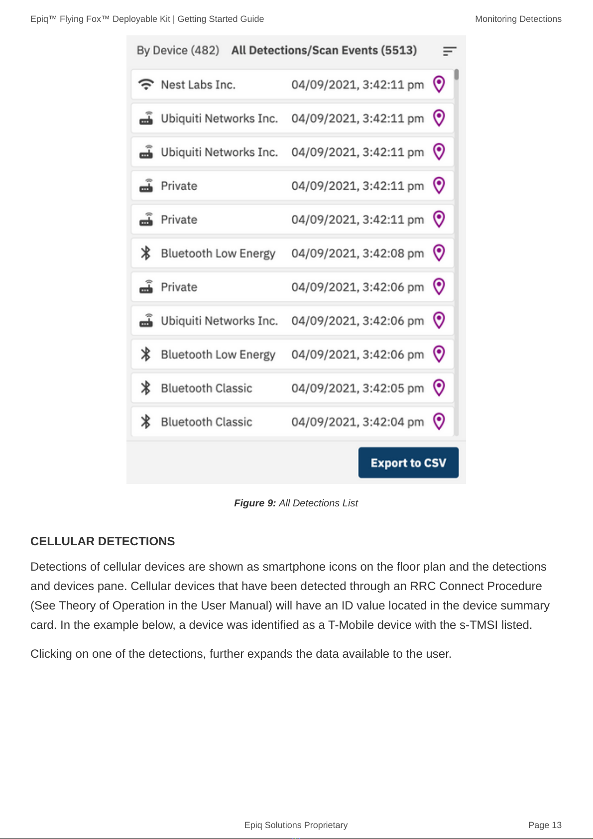
The list of detections can be viewed in two modes: By Device or All Detections. When viewing By
Device, the list will show cards for each detected device and will list the number of recent detections
for that device. This view is shown above. When viewing All Detections, the list will show individual
detection events which is shown below.
MONITORING DETECTIONS
GROUPING BY DEVICE OR EVENT
Epiq™ Flying Fox™ Deployable Kit | Getting Started Guide Monitoring Detections
Epiq Solutions Proprietary Page 13
Figure 9: All Detections List
Detections of cellular devices are shown as smartphone icons on the floor plan and the detections
and devices pane. Cellular devices that have been detected through an RRC Connect Procedure
(See Theory of Operation in the User Manual) will have an ID value located in the device summary
card. In the example below, a device was identified as a T-Mobile device with the s-TMSI listed.
Clicking on one of the detections, further expands the data available to the user.
CELLULAR DETECTIONS

Epiq™ Flying Fox™ Deployable Kit | Getting Started Guide Monitoring Detections
Epiq Solutions Proprietary Page 14
Figure 10: Cellular Detection Example
For each detection event associated with this device, band and channel information as well as
sensors involved and power levels are presented.
Sensors that are involved in the estimate of detections can be highlighted by clicking the "Highlight
Active Sensors" option.
Figure 11: Cellular Detection Example
Cellular detections with "ID TYPE" listed as "UNKNOWN" are groups of detections where the
complete RRC Connect Procedure was not fully decoded, and therefore the device's temporary
Unknown Cellular Detections

Epiq™ Flying Fox™ Deployable Kit | Getting Started Guide Monitoring Detections
Epiq Solutions Proprietary Page 15
identifier was not captured. Without the identifier, the system is unable to uniquely identify each
transmission. In these cases, different devices may be transmitting at the same time and therefore
location data may be unreliable.
Figure 12: Bluetooth Detection Example
Detections of Bluetooth Classic and Bluetooth Low Energy (LE) devices will be shown on the
floorpan as well as the detection and devices pane. Detected Bluetooth devices will have their MAC
address in the device card, and additional information about each detection is available by clicking
the detections list.
Sensors that are involved in the estimate of detections can be highlighted by clicking the "Highlight
Active Sensors" option.
BLUETOOTH DETECTIONS

Epiq™ Flying Fox™ Deployable Kit | Getting Started Guide Monitoring Detections
Epiq Solutions Proprietary Page 16
Figure 13: Bluetooth Detection Example
The device can be given an alias / friendly name by clicking the pencil icon beside the device name
in the device card. Additionally, a user can search for devices by entering the friendly name, MAC
address, carrier, technology, or manufacturer in the search bar.
Figure 14: technology selector
Detections of Wi-Fi devices will be shown on the floor plan as well as the detection and devices
pane. Detected devices will have their MAC address in the device card, and additional information
about each detection is available by clicking the detections list.
WI-FI DETECTIONS

Epiq™ Flying Fox™ Deployable Kit | Getting Started Guide Monitoring Detections
Epiq Solutions Proprietary Page 17
Sensors that are involved in the estimate of detections can be highlighted by clicking the "Highlight
Active Sensors" option.
The device can be given an alias / friendly name by clicking the pencil icon beside the device name
in the device card.

Epiq™ Flying Fox™ Deployable Kit | Getting Started Guide Troubleshooting
Epiq Solutions Proprietary Page 18
Verify the client has connectivity to the Flying Fox Enterprise Appliance.
Verify the Flying Fox Enterprise controller is running.
Verify connectivity to the sensors.
This is usually caused by an inaccurate location estimate. To hide these estimates see the Excluding
Possible Unreliable Location Estimates section in the user manual.
TROUBLESHOOTING
Can't Connect to Flying Fox Enterprise Web Page
Sensors are Not Populating in Sensor List
Devices From Outside the Zone are Showing Up Inside the Zone on the Floor Plan

Table of contents


