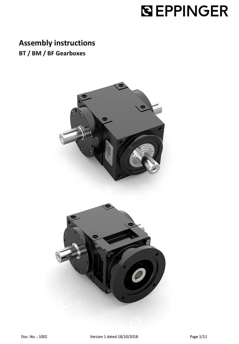
EPPINGER HT Series User manual

Doc. No.: 1001 Version 2 dated 21/01/2019 Page 1/15
Assembly instructions
HT / SHT Gearboxes

Assembly instructions
(translation)
HT / SHT Gearbo es
Doc. No.: 1001 Version 2 dated 21/01/2019 Page 2/15
Table of contents
1
Safety instructions ............................................................ 3
2
General ............................................................................... 3
2.1
Information on the documentation ........................................... 3
2.2
Target group ................................................................................ 4
2.3
Scope ............................................................................................ 4
2.4
Intended use ................................................................................ 4
2.5
Contact ......................................................................................... 5
3
Handling and Transport .................................................... 5
4
Storage ............................................................................... 5
5
Assembly ............................................................................ 5
5.1
Mounting of the gearbo ........................................................... 6
5.2
Assembly of the output shaft ..................................................... 6
5.2.1
Assembly of gearbo es with solid output shaft ......................... 7
5.2.2
Assembly of gearbo es with hollow output shaft ..................... 7
5.3
Motor assembly............................................................................ 9
6
ommissioning ................................................................ 10
7
Operation ......................................................................... 11
8
Maintenance .................................................................... 12
9
Decommissioning ............................................................ 13
9.1
Dismantling ................................................................................ 13
9.1.1
Disassembly of gearbo es with solid output shaft .................. 13
9.1.2
Disassembly of gearbo es with hollow output shaft ............... 13
9.1.3
Motor disassembly ..................................................................... 14
9.2
Disposal ...................................................................................... 14

Assembly instructions
(translation)
HT / SHT Gearbo es
Doc. No.: 1001 Version 2 dated 21/01/2019 Page 3/15
1 Safety instructions
A distinction is made between different levels of safety instructions. Ta-
ble 1 below shows the definitions of symbols and signal words.
Symbol Signal
word
Definition
DANGER! Immediately imminent danger.
Death or e tremely serious injury, crippling.
WARNING!
Possibly dangerous situation.
Death or e tremely serious injuries may re-
sult.
AUTION! Less dangerous situation.
Minor or moderate injuries may result.
NOTI E Potentially damaging situation.
Possible damage to product and/or machine.
INFO
Tips and other useful or important infor-
mation and advice.
No dangerous or harmful consequences for
persons or property.
Table 1: Classification of notices
Symbol Signal word Definition
Environmental
hazard
Pollution risk for the environment
Table 2: Other symbols
2 General
2.1 Information on the documentation
These assembly instructions have to be read carefully before assembling,
commissioning and maintaining the product. The document must be

Assembly instructions
(translation)
HT / SHT Gearbo es
Doc. No.: 1001 Version 2 dated 21/01/2019 Page 4/15
kept in a suitable place for future reference and must be available for
any assembly, maintenance or dismantling work.
2.2 Target group
This documentation is intended for qualified trained personnel who are
familiar with mechanical assembly work. Assembly, commissioning and
maintenance may only be carried out by accordingly qualified personnel.
Technical training or safety instruction is required.
2. Scope
The scope of these instructions covers the following products of the
company EGT Eppinger Getriebe Technologie GmbH:
HT Hypoid gearbo es
SHT Hypoid helical gearbo es
All mounting parts necessary for the assembly, installation, operation
and maintenance, which are included in the scope of supply of these
gearbo es, are also within the scope of this document.
2.4 Intended use
Eppinger gearbo es are machine elements for converting or diverting
torques and rotational speeds within the respectively specified perfor-
mance range. Any operation outside the specified performance charac-
teristics or other than the specified use is not permitted. The permissible
torques and rotational speeds of the gearbo es must not be e ceeded.
The forces affecting on the gearbo shafts have to be limited to the ma -
imum permissible values.
Unauthorised modifications or alterations to the product are not permit-
ted.
According to the EC Machinery Directive 2006/42/EC, gearbo es are re-
ferred to as machine components and are therefore assemblies that do
not fall within the scope of the Machinery Directive 2006/42/EC. There-
fore, gearbo es are components to be installed in machines. The commis-
sioning is forbidden until by or after the integration into the end prod-
uct, the requirements of the machine directives are met.

Assembly instructions
(translation)
HT / SHT Gearbo es
Doc. No.: 1001 Version 2 dated 21/01/2019 Page 5/15
2.5 Contact
EGT EPPINGER Getriebe Technologie GmbH
Breitwiesenweg 2-8
73770 Denkendorf/Germany
+49 (0) 711 / 934 934-626
http://www.eppinger-gears.com
Handling and Transport
DANGER!
Death or e tremely serious injury / crippling caused by falling loads.
During transport, never stay under suspended loads.
The weights indicated in Table 3 apply to gearbo es without motor
flange and with solid output shafts on both sides.
Gearbox SHT100
HT90
SHT120
HT115
SHT150
HT140
HT170
HT215
Weight
about
4 kg 6 kg 10 kg 16 kg 35 kg
Table 3: Weights
4 Storage
The gearbo es have to be stored protected from dust, dirt and moisture.
The temperature has to be between -5°C and +40°C.
5 Assembly
AUTION!
Assembly work may only be carried out by accordingly qualified trained
personnel.First of all, check the gearbo for e ternal damage.

Assembly instructions
(translation)
HT / SHT Gearbo es
Doc. No.: 1001 Version 2 dated 21/01/2019 Page 6/15
AUTION!
A damaged gearbo must not be operated.
Before installing the gearbo , always switch off the machine and secure
it against a restart. In addition is has to be ensured that the machine
cannot move.
DANGER!
Death or e tremely serious injury / crippling caused by moving machine
elements when accidentally switched on or by accidentally releasing
stressed components during assembly.
Before installation, check the direction of rotation of the gearbo . The
direction of rotation of the gearbo can be gathered from the data
sheet.
5.1 Mounting of the gearbox
The gearbo has to be securely screwed to the application. Special atten-
tion has to be paid to a flat support.
The centring collar on the output end of the gearbo housing can be
used for the e act centring of the gearbo . The dimensions as well as the
tolerances can be gathered from the data sheet.
All e isting mounting holes must always be used on the selected screw-
on side. At this, the screw tightening torque depends on the strength
class of the screw as well as the material of the bearing face respectively
the internal thread. The thread reach has to be chosen according to the
strength class of the screw as well as the material of the internal thread.
5.2 Assembly of the output shaft
When mounting the output shaft, appropriate torque transmission must
be ensured. In the gearbo es of the HT and SHT series, a basic distinction
is made between solid shaft gearbo es (Figure 1) and hollow shaft gear-
bo es (Figure 2).
The assembly of these two variants is described respectively in the fol-
lowing chapters 5.2.1 for gearbo es with solid output shaft and 5.2.2 for
gearbo es with hollow output shaft.

Assembly instructions
(translation)
HT / SHT Gearbo es
Doc. No.: 1001 Version 2 dated 21/01/2019 Page 7/15
DANGER!
Risk of injuries due to a slipping of the shaft. The torque cannot be reli-
ably transmitted, if the shaft is not assembled according to the indicat-
ed requirements.
5.2.1 Assembly of gearboxes with solid output shaft
This chapter describes the assembly of the output shaft for gearbo es
with a solid shaft (Figure 1). The solid output shaft is designed plain and
without a keyway or spline profile. Torque transmission can, for e am-
ple, take place backlash-free by means of clamping couplings, clamping
bushings or heat shrinking of components onto the shaft. For the chosen
transmission principle, the e isting specification of the manufacturer of
the coupling respectively the clamping sleeve must be observed.
When heat-shrinking components onto the gear shaft, a clean and
grease or oil-free gear shaft must be ensured.
The gear shaft must not be heated too much by the hot component be-
cause the adjacent radial shaft seals on the gear shaft could be damaged.
NOTI E
Damage to the radial shaft seals due to heat shrinking of components
that are too hot onto the gear shafts.
5.2.2 Assembly of gearboxes with hollow output shaft
This chapter describes the assembly of the output shaft for gearbo es
with a hollow shaft (figure 2). The hollow output shaft is designed plain
Figure 1: Gearbox with solid shaft
Figure 2: Gearbox with hollow shaft

Assembly instructions
(translation)
HT / SHT Gearbo es
Doc. No.: 1001 Version 2 dated 21/01/2019 Page 8/15
and without a keyway or spline profile. The torque transmission as well
as a ial securing takes place backlash-free by clamping the customer
shaft in the hollow shaft by means of a shrink disc. This shrink disc cre-
ates a frictional connection between the hollow gear shaft and the cus-
tomer's solid shaft by means of taper bushings.
The customer's shaft has to meet the following characteristics:
Yield strength Re ≥ 340 N/mm²
E-Module about 206 kN/mm²
Average surface roughness Ra ≤ 3.2 µm
Shaft tolerance h6 in the area of the shrink disc
DANGER!
Risk of injuries due to a slipping of the shaft. The torque cannot be reli-
ably transmitted, if the shaft is not manufactured according to the re-
quirements indicated above or if the shrink disk is not properly assem-
bled.
Prior to the assembly clean and de-
grease the machine shaft as well as
the hollow gear shaft.
After the shaft has been inserted in-
to the hollow shaft of the gearbo ,
the clamping screws of the shrink
disc must be tightened evenly in turn
by ¼ turns until the front face of the
stepped tapered ring is flush with
the front face of the stepped ta-
pered bushing. (Figure 3)
INFO
The assembly of the shrink disc is carried out in a path-controlled man-
ner. It is not necessary to use a torque wrench.
Figure 3: ssembly of the shrink disc

Assembly instructions
(translation)
HT / SHT Gearbo es
Doc. No.: 1001 Version 2 dated 21/01/2019 Page 9/15
NOTI E
The shrink disc must only be tightened, if the machine shaft is inserted.
A tightening of the locking screws could otherwise deform the hollow
gear shaft.
5. Motor assembly
For gearbo es with an attached motor flange and a drive coupling, prior
to the assembly of the motor, the coupling has to be aligned in such a
manner that the clamping screw of the coupling can be tightened via the
through hole of the locking screw in the motor flange (Figure 4).
INFO
For gearbo es with an integrated dismantling system, the clamping hub
can be widened by means of the clamping screw for an easier assembly.
For this, the clamping screw has to be unscrewed until it is widening the
clamping hub beyond the dead stop by means of a further unscrewing.
For motors with a key, this has to be re-
moved prior to the assembling. The key-
way must be aligned in such a manner
that it matches the notch of the coupling
hub (Figure 4).
Carefully introduce the motor shaft into
the coupling bore. The motor shaft has to
be introduced steadily at a right angle
and concentrically to the bore. An angu-
lar or lateral misalignment during move-
ment of the motor shaft can damage the
coupling bellows. An a ial deformation of the coupling bellows, e.g. by a
canting of the motor shaft during the introduction into the coupling is
not permissible.
NOTI E
Damaging of the coupling by a lateral, a ial or angular displacement of
the coupling bellows by the motor shaft during the assembling.
After the motor has been inserted until the motor
plate is in contact with the gearbo flange, screw
the motor to the gearbo flange. Take care of the
Figure 5
: Length of the
screw
Figure 4
: lignment of coupling
and motor shaft

Assembly instructions
(translation)
HT / SHT Gearbo es
Doc. No.: 1001 Version 2 dated 21/01/2019 Page 10/15
thread reach of the bolts. The thread reach of the motor flange shall be
twice the length of the nominal diameter of the screw. (Figure 5)
After that, clamp the motor shaft in the coupling. The clamping screw of
the coupling can be reached through the through hole of the locking
screw in the motor flange. (Figure 4). The torque to be used as well as
the wrench size can be gathered from Table 4.
Gearbox SHT100
SHT120
HT90
SHT150
HT115
HT140
HT170
HT215
Tightening
torque
4 Nm 4.5 Nm 8 Nm 15 Nm 40 Nm 85 Nm
Width across
flats
AF3 AF3 AF4 AF5 AF6 AF8
Table 4: Tightening torques / wrench sizes coupling clamping screw
NOTI E
Damaging of the coupling
The coupling has to be screwed together with a bellows free from a ial
loads.
6 Commissioning
AUTION!
The commissioning may only be carried out by accordingly qualified
trained personnel.
Before commissioning, all mechanical mounting parts and their fastening
must be checked. Check the screw tightening torques. Commissioning
may only take place if the machine complies with the provisions of the
EC Machinery Directive. The monitoring and protective devices of the
machine must not be put out of operation. In addition to EMERGENCY
STOP buttons, EMERGENCY STOP command devices, covers and hoods,
this also includes other protective devices such as sensors, light barriers
and acoustic or optical emergency signals. The security of the gearbo

Assembly instructions
(translation)
HT / SHT Gearbo es
Doc. No.: 1001 Version 2 dated 21/01/2019 Page 11/15
can only be assured by the end product. Therefore, any commissioning
with overridden protection equipment of the machine is not permitted.
DANGER!
Death or e tremely serious injury / crippling caused by equipment in
operation without suitable safety or protective devices by the surround-
ing end product.
7 Operation
AUTION!
The gearbo may only be operated by accordingly qualified trained per-
sonnel.
The gearbo may only be operated with active protective and monitor-
ing equipment of the machine.
DANGER!
Death or e tremely serious injury / crippling caused by equipment in
operation without suitable safety or protective devices by the surround-
ing end product.
WARNING!
Burns at hot surfaces.
During operation, the surface of the gearbo can reach high tempera-
tures. It must be ensured that there is no unintentional contact with the
surface of the gearbo .
During the operation, the gearbo should be observed.
Leakage, unusual temperature rises or an increase in the noise respec-
tively vibration indicate a fault which has to be repaired. If one of these
criteria should occur, the plant has to be shut down immediately. If the
fault cannot be eliminated, contact EGT Eppinger
(chapter 2.5).

Assembly instructions
(translation)
HT / SHT Gearbo es
Doc. No.: 1001 Version 2 dated 21/01/2019 Page 12/15
8 Maintenance
AUTION!
Maintenance may only be carried out by accordingly qualified trained
personnel.
As a matter of principle, the HT and SHT gearbo es of the company EGT
Eppinger are maintenance free and lubricated for life.
For special gearbo es and gearbo es with operating conditions outside
the specification, any separately communicated maintenance intervals
and specifications apply.
INFO
Synthetic oil according to DIN 51517-3:2018-09 with viscosity class ISO
VG 150 is used as standard lubricant.
NOTI E
Damages to the gearbo by a reduced lubricity.
Different lubricants must not be mi ed. This may result in a reduced lu-
brication effect and a damaging of the gearbo .
DANGER!
Risk of burns during the oil change by hot gearbo oil.
AUTION!
Skin irritation by intensive contact with synthetic oil.

Assembly instructions
(translation)
HT / SHT Gearbo es
Doc. No.: 1001 Version 2 dated 21/01/2019 Page 13/15
9 Decommissioning
AUTION!
Dismantling and disposal may only be carried out by accordingly quali-
fied trained personnel.
9.1 Dismantling
Before dismantling the gearbo , always switch off the machine and se-
cure it against a restart. In addition is has to ensured that the machine
cannot move.
DANGER!
Death or e tremely serious injury / crippling caused by moving machine
elements when accidentally switched on or by accidentally releasing
stressed components during dismantling.
9.1.1 Disassembly of gearboxes with solid output shaft
In the case of gearbo es with solid shaft (Figure 1), loosen the mounted
coupling or clamping hub if necessary according to the manufacturer's
instructions.
9.1.2 Disassembly of gearboxes with hollow output shaft
In the case of hollow shaft gearbo es with a shrink disc (Figure 2), all
clamping screws of the shrink disc must be loosened in turn by ¼ turns.
WARNING!
Never unscrew all clamping screws of the shrink disc completely from
the threaded holes during dismantling, otherwise there is a risk of acci-
dent!
If the two rings do not come loose on their own, unscrew as many clamp-
ing screws as there are pull-off threads in the stepped conical bushing
and screw them steadily into the press-off threads until the stepped ta-
pered ring is pulled off the stepped tapered bushing.

Assembly instructions
(translation)
HT / SHT Gearbo es
Doc. No.: 1001 Version 2 dated 21/01/2019 Page 14/15
9.1. Motor disassembly
To loosen the clamping hub of the coupling, rotate it so that the clamp-
ing screw of the coupling can be reached via the bore in the motor
flange. (Figure 4, Page 9)
This can be carried out, for e ample, by manual rotating the output shaft
of the gearbo .
Loosen the clamping screw of the coupling. The wrench size can be
gathered from Table 4 (page 10).
INFO
For couplings with an integrated dismantling system, the clamping hub
can be widened by means of the clamping screw for an easier disman-
tling. For this, unscrew the clamping screw until it is widening the
clamping hub beyond the dead stop by means of a further unscrewing.
After the loosening of the clamping coupling, the motor screw joint can
be unscrewed.
WARNING!
Risk of injury.
The motor is only attached with the motor screw joint. After the loosen-
ing of the motor screw joint, the motor can suddenly draw loose.
Pull out the motor steadily and as concentrically as possible from the
coupling.
NOTI E
Damaging of the coupling by a lateral, a ial or angular displacement of
the coupling bellows by the motor shaft during the dismantling.
9.2 Disposal
ENVIRONMENTAL HAZARD!
Environmental compatibility, health risks, disposal regulations and the
local possibilities of proper disposal must be observed.
Any and all operating materials, in particular oils, fats and lubricants are
to be disposed of according to the national and regional applicable
regulations.

Assembly instructions
(translation)
HT / SHT Gearbo es
Doc. No.: 1001 Version 2 dated 21/01/2019 Page 15/15
AUTION!
Skin irritation by intensive contact with synthetic oil.
This manual suits for next models
9
Table of contents
Other EPPINGER Industrial Equipment manuals
Popular Industrial Equipment manuals by other brands

Kobelt
Kobelt 5020-M Series Owner's Operation, Installation & Maintenance Manual
Matweld
Matweld 01200 Service manual

Dr.X Works
Dr.X Works BHW-L product manual
MSD
MSD Mallory E-Spark Conversion 61001M installation instructions

Danfoss
Danfoss H1F 080 Service manual

Walinga
Walinga Central Vac Operator and parts manual
