ti.systems CTISr User manual
tire inflation systems
made in Germany
Operation manual
CTISr
Central Tire Inflation System removable
Welserstraße 1 |41468 Neuss |Germany
tel +4 2131. 1 53 18–0 mail info@ti.systems
fax +4 2131. 1 53 18–2 web www.ti.systems
ti.systems GmbH

Certified to DIN EN ISO 001:2015
DIN EN ISO 14001:2015
CTISr

33
Table of Contents
4 General Safety Information
4 Introduction
4 Safety Instructions and Warnings
6 Product Description
6 Product safety Instructions and Warnings
Operation | use
7
8 Adjusting the tire pressure
Storing the hose packets
10 Disconnecting the hoses from the rear axles
Connecting the hose packets to the coupling units and rotary unions
10 Dierent pressure settings by axle
10 Conventional tire pressure check
CTISr
11 Potential Faults and Troubleshooting
11 Disposal
11 Technical Data

4
General Safety Information
1. Introduction
Dear Customer,
You have purchased a product that conforms to the latest
state of the art. Please make sure to install, use and
maintain it as detailed in these operating instructions to
provide you with years of reliable use.
The product as supplied meets all functional and quality
requirements. In order to maintain its state and ensure
risk-free operation, you as the fitter and / or user will need
to read and understand these instructions.
If you have any queries please contact:
ti.systems GmbH
Welserstraße 1 |41468 Neuss |Germany
tel: 02131. 1 53 18–0
mail: info@ti.systems
1.1. Copyright
These operating instructions are a publication of
ti.systems GmbH. All rights, including translation, are
reserved. No part of these instructions may
be replicated in any form or stored in data processing
systems without the written consent of the publisher.
Reproduction in full or in part is not permitted. These
operating instructions reflect the current technical
specifications at the time of printing. We reserve the right
to changes in technology and equipment.
© Copyright 2016 by ti.systems GmbH
1.2.Intended use
The CTISr is intended to be used for inflation and deflation
of the tires of commercial vehicles or private expedition
vehicles with compressed air supply from the vehicle
compressor or a stationary compressor while the vehicle is
stationary and, if necessary, with the engine running.
Pneumatic tools may be operated additionally using the
separate coupling connector on the control box. Any other
use is not permitted and may cause damage to the
product. Do not inflate any other items.
Components of the system may not be transported in an
unsecured state in or on the vehicle. Do not modify the
product. Always follow the safety instructions!
1.3. Disclaimer
Defects caused by failure to comply with these operating
instructions will invalidate the warranty. ti.systems GmbH
takes no responsibility for consequential damage incurred
as a result.
2. Safety Instructions and Warnings
2.1. Basic safety instructions
• When carrying out work on the product, always secure
the vehicle against rolling away or tipping over. Switch
the engine o.
• When carrying out work on the product, always secure
the product against unintentional restarting. If neces-
sary, switch o the product and/ or disconnect it from
the power supply.
• Always ensure secure positioning of the product when
carrying out work which cannot be performed from
the ground. Use steps and grips or handles where
available. If necessary, use suitable aids.
• The product, or its parts, are permanently or tempora-
rily under pressure.
• Hoses or pipes which come uncoupled under pressure
may whip and cause serious injury. When carrying out
work on the product, always ensure that the product
and its parts are not under pressure. If work without
pressure is not possible, take the recommended safety
precautions and wear the recommended personal pro-
tective equipment (PPE). Keep other people away
from the danger zone.
CTISr
5
2.2. Types and meaning of safety information
Some processes need to be carried out in several steps.
Where any of these steps involves a risk, the safety advice
is included directly in its instructions.
The safety advice always precedes the risky step and is
printed in normal type using a signal word in bold and
capitals.
Example:
1. NOTE: Please note this information. It warns of a risk
involved in the next step.
2. Risky step.
• The operating controls of the product should be easy
to access and allow operation without risk of contact
with hot, sharpedged or moving parts.
• Always fit the product and / or components in such a
way that the controls/indicators and safety information
of the vehicle and /or other devices are not obstructed.
• The visibility range of the driver must not be obstructed
by fitted system components.
• Before using the product, familiarise yourself with its
features and operation. Always follow these operating
instructions.
• Do not use this product to inflate or deflate tires that
are not in good condition.
• When inflating tires always keep away from the
danger zone. Always follow the safety instructions of
the tire manufacturer.
• Always ensure that the tire pressure is within the
minimum and maximum range permitted by the tire
manufacturer taking account of the current wheel/axle
loads and the expected driving speed of your vehicle.
• In case of additional stresses due to dynamic wheel /
axle load shifts (e.g. when driving on inclines or slopes,
heavy pulling, heavy accessory equipment), adjust the
tire pressure in accordance with the manufacturer’s
instructions.
• Damaged parts may aect the operational safety of
the product and / or cause serious injury and therefore
must be immediately replaced with original parts.
• Never operate defect products and / or components.
DANGER indicates a risk that WILL result in serious
injury or death if not observed.
DANGER
WARNING indicates a risk that MAY result in serious
injury or death if not observed.
WARNING
CAUTION indicates a risk that MAY cause minor
injury.
CAUTION
NOTE indicates a risk that MAY cause material da-
mage or malfunctioning of the product, the vehicle
or other equipment.
NOTE
CTISr

6
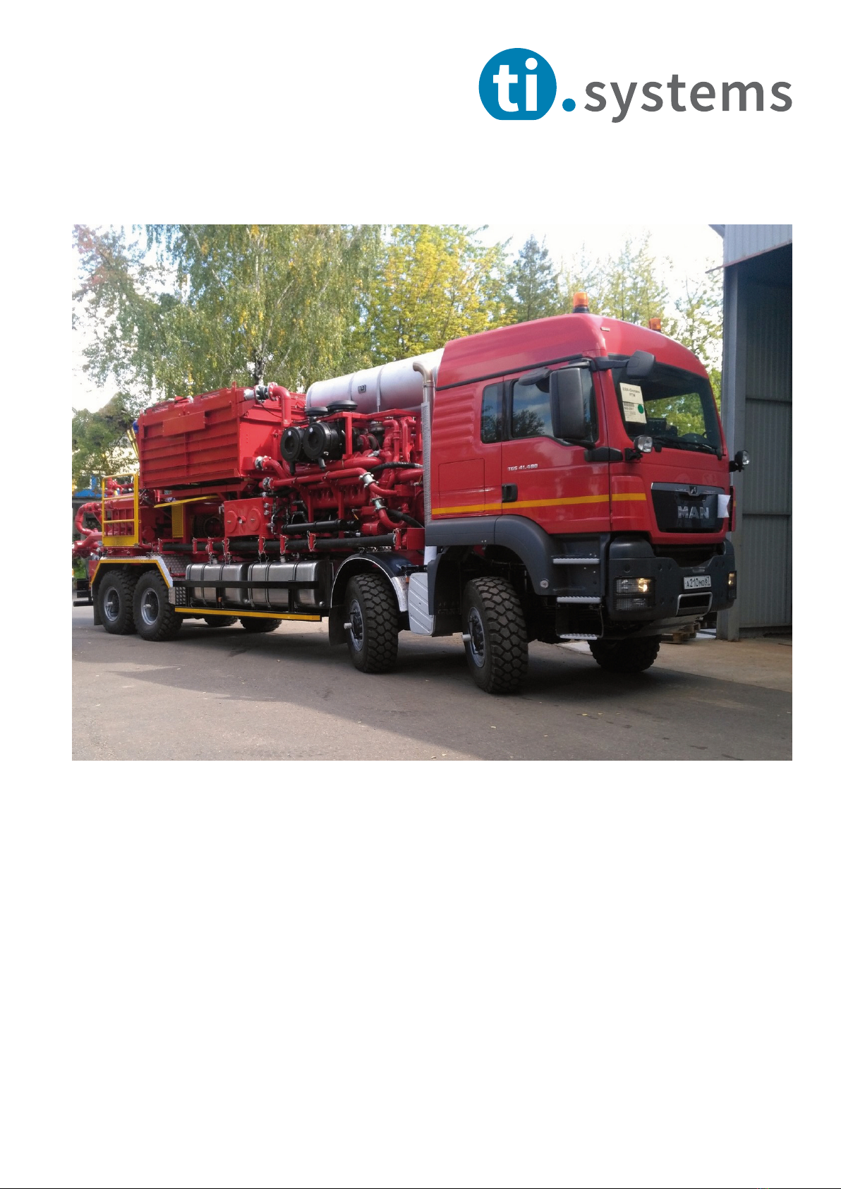
Product description
The CTIS comprises the control unit, dual chamber
rotary unions for each wheel and tire valve connectors
on the tire valves as well as connecting tubes from the
control unit to the dual chamber rotary unions and the
air brake circuit.
The contol unit must be supplied with compressed air
for tire inflation from the vehicle (brake system priority
circuit).
Product safety Instructions and Warnings
The control unit must be easy to access and operate
without risk of contact with hot, sharp-edged or moving
parts.
Do not operate defect components. Hoses or pipes
which come uncoupled under pressure may whip
and cause serious injury. Exercise caution when
using pressure lines.
DANGER
NOTE
Always replace damaged parts immediately.
NOTE
CTISr
Operation | use
1. Connecting the hose packets to the coupling units and rotary
unions
Front axle:
Unclasp the snap hook to open the hose depot, remove the lid and
take out the required hose packets.
The hose packets are fitted with plug fittings on one end and with
lock couplings on the other. This means they cannot be connected in
the wrong way. The hose packets are braced at the plug fitting end to
prevent contact between the hose packet and tire/rim. Occasional
contact, especially in extreme situations, is not likely to cause a
problem.
Remove the protection caps from the plug fittings of the rotary
unions and from the couplings of the coupling unit.
Connect the hose packets successively, snapping the plug couplings
and plug fittings into place.
Rear axles:
The hoses are already connected to the tires from the initial
installation.
CTISr
7
Image 1

. Adjusting the tire pressure
The CTISr only works with the hoses connected and the ignition
switched on.
Once the compressed air system provides enough pressure, the 1l air
tank is filled and supplies the operating pressure for the control
panel.
The rotary switch is used to select between four dierent preset tire
pressures:
Highway (HWY)
O-road (OFR)
Sand | Mud (S/M)
Emergency (EMC)
Turn the ON|OFF switch to “ON”. This opens the tire valves to
regulate the selected pressure via the main control unit.
The pressure indicated on the actual pressure gauge moves towards
the preselected pressure. Due to the flow process, particularly when
deflating the tire, the indicated (dynamic) pressure is not the exact
same as the (static) pressure in the tires. The correct pressure will
only be indicated towards the end of adjustment.
When the required target pressure is reached, turn the ON|OFF
switch back to “OFF” to close the tire valves and depressurise the
rotary unions.
If the vehicle has previously been used to navigate mud flats, it is
advisable to set the control pressure initially below the current tire
pressure to activate the proportional valve so it lets pressure o via
the potentially soiled silencer and cleans the filter element.
CTISr
8
Image 2
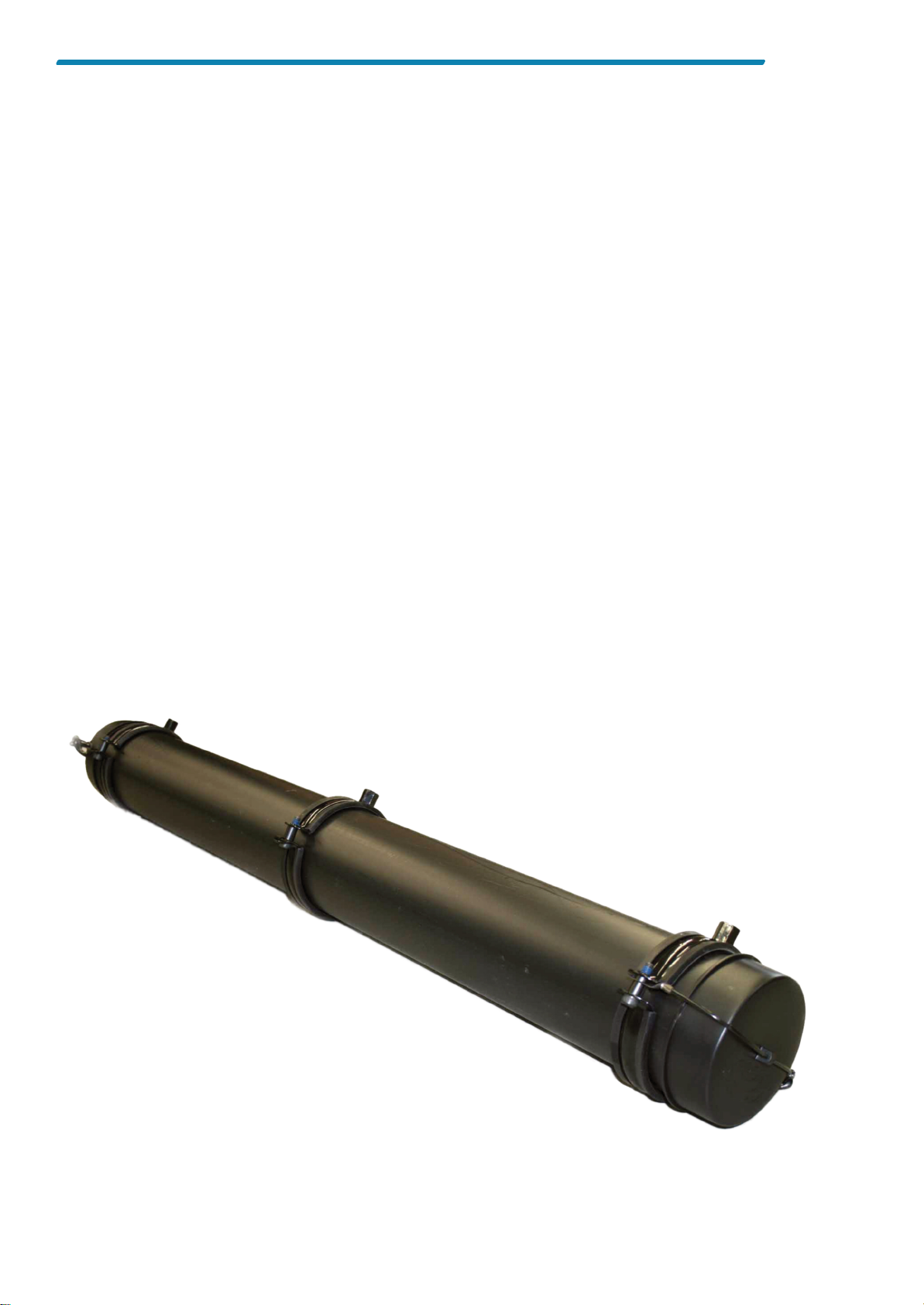
3. Storing the hose packets
When driving on public roads, local regulations may require
that the hose packets be removed from the rotary unions
and coupling units and be stored in a hose depot.
Switch o the system and disconnect the hose packets from
the rotary unions and the coupling units.
Unclasp the snap hook to open the hose depot, remove the
lid and store the hose packets inside. Close the lid and snap
the hook back into the D-ring on the hose depot.
CTISr
9
Image 3

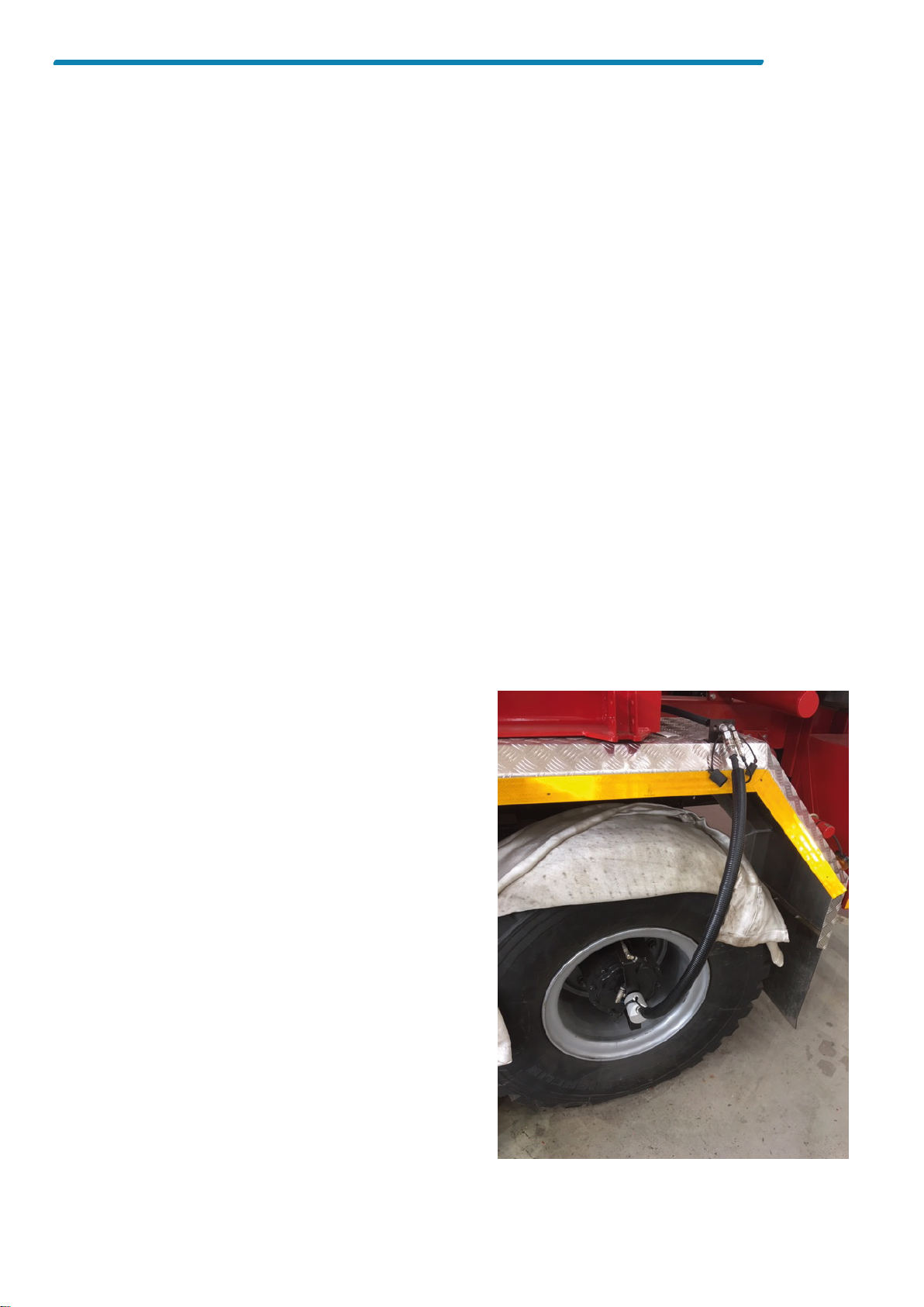
4. Disconnecting the hoses from the rear axles
In case the hoses from the rear axles have to be
disconnected from the rotary unions (e.g. for tire changing,
replacing the rotary union etc.), disconnect the couplings of
the working line (PA 12x1.5 bk) and the control line (PA 4x1
bl) from the rotary union. Then connect the two lines to the
blind connectors S26 and S21, which are installed on the
mud guard between the two rear wheels.
5. Dierent pressure settings by axle
To set dierent pressures by axle, follow these two steps:
First, connect all vehicle tires and inflate them to the lower
pressure required. Disconnect the lines that have reached
the target pressure and disconnect the hoses. Now select
the higher inflation pressure of the remaining tires and
proceed as described under 2.
When deflating, deflate all tires to the higher pressure,
disconnect the “finished” tires. Now select the lower
pressure on the control unit for the remaining tires.
6. Conventional tire pressure check
The tire pressure can always be checked or adjusted in the
conventional way by connecting the supplied gas station
adapter TIS-X-010-00 to the ti.systems tire valve.
CTISr
10
Image 4

Potential Faults and Troubleshooting
Tires do not inflate
• Pressure in the supply system is lower than the
current tire pressure or too low to overflow the
priority circuit of the brake system
fill brake air reservoir
• System has no power
replace fuse
• Hoses not properly connected to tire valves
connect properly
• Main control valve defect
replace valve in the workshop
• Pressure controller defect
replace controller in the workshop
Tires do not deflate
• Filter element of silencer excessively soiled
clean up silencer
• Hoses not properly connected to tire valves
connect properly
• Main control valve defect
replace valve in the workshop
• Pressure controller defect
replace controller in the workshop
• Valve inserts still in tire valves
remove the inserts from the tire valves and mount
ti.systems connectors properly
Disposal
If the system fails to work properly and can no longer be
repaired, please dispose of the product in compliance
with the applicable legal requirements.
Technical data
Maximum operating pressure: 12.5 bar
Adjustment range: 0.5 bar p 6.5 bar (single tires)
Thermal application range: -40°C – +70°C
Fording ability: yes
8.5 bar (twintires)
Certified to DIN EN ISO 001:2015
DIN EN ISO 14001:2015
11
Table of contents
Popular Industrial Equipment manuals by other brands


Ulvac
Ulvac OMT-050A instruction manual

Logan
Logan F400-1 instruction manual

Metra Electronics
Metra Electronics ADS-200 operating manual

SUHNER ABRASIVE
SUHNER ABRASIVE LTB 6 - 1030 Technical document

PCB Piezotronics
PCB Piezotronics ICP J353B31 Installation and operating manual

RS
RS V3681 Instruction leaflet