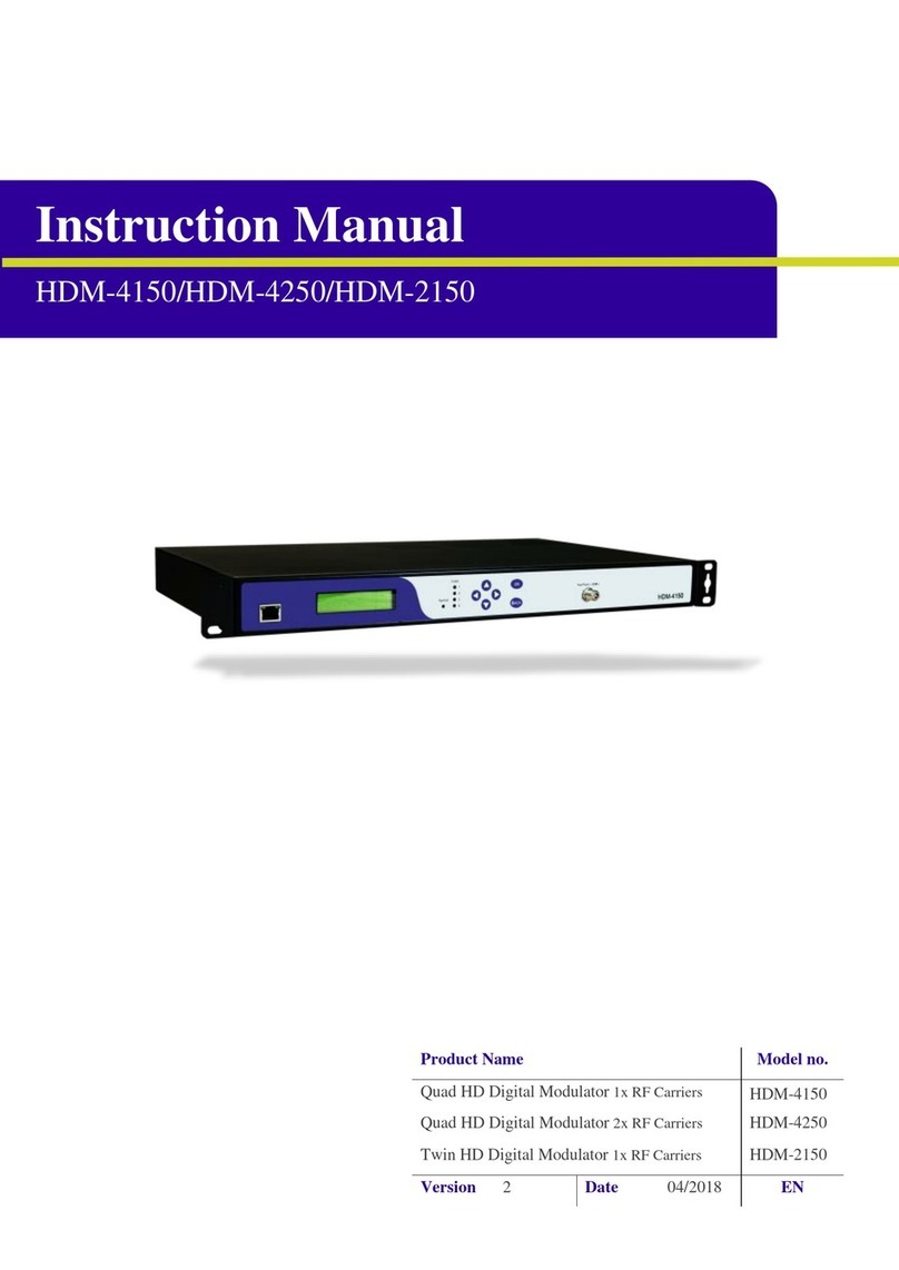
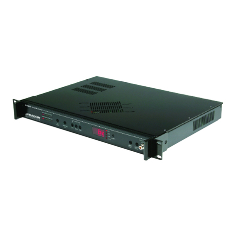
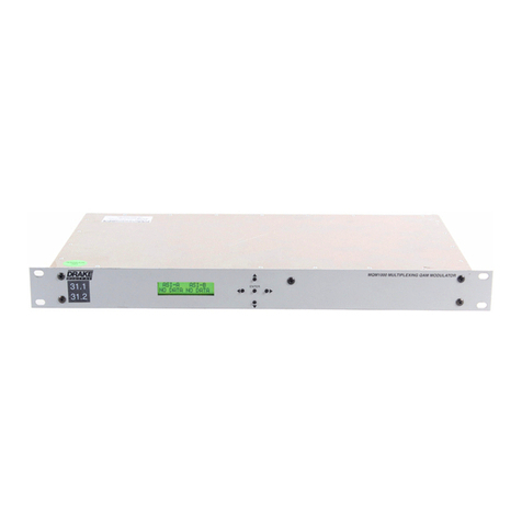
EPS Ecraft Pro Series User manual

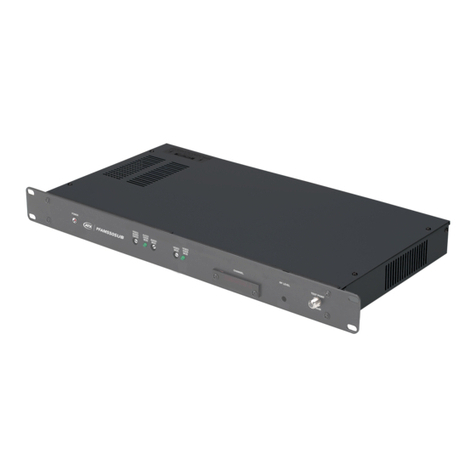
EPS-HDM1004ECO
4 HDMI input Encoder Modulator
ELECTROCRAFT AUSTRALIA 36 Binney Road, Marayong NSW 2148 T: (02) 8811 5155 F: (02) 9831 2139
www.electrocraft.com.au

Chapter 1 Introduction
1.1 Product Overview
EPS-HDM1004ECO encoder modulator is all-in-one device integrating MPEG2
encoding and modulating to convert audio/video signals into D B-T RF out. It
support 4 HDMI inputs. The signal source could be from STB, satellite receiver,
closed-circuit television cameras and antenna etc. Its output signal is to be
received by T s or STBs etc.
1.2 Ke Features
Support 4 HDMI channels input
Support MPEG2 video encoding
Support 1080p/i,720p, 576i , 480i video resolution
Support low latency(50~1000ms)
Support MPEG-1 layer 2, MPEG-2 AAC, and AC3 audio encoding
Support CC (Closed Caption), EIA 608
Support LCN(Logical Cluster Number)
D B-C/T/ATSC/ISDB-T/DTMB RF out in one device, modulation dynamic switching
Each channel support 1 D B-C/T/ATSC/ISDB-T/DTMB output option
Control via web-based NMS, and easy updates via web

1.3 Specifications
HDMI Encoding Section
Input Interface HDMI*4
Video
Encoding MPEG2
Input Output
576@50i 576@25
720@50/59.94/60 720@25/30
1080@50i 1080@25
1080@50 1080@25
Bit-rate 2.000~20.000 Mb s
GOP 1~60
Rate Control VBR
As ect Ratio 16 :9
Audio Encoding MPEGI layer 2,MPEG-2AAC, AC3
Sam le rate 48KHz
Bit rate
MPEGI layer 2 (128kb s)
MPEG-2 AAC (VBR)
AC3 (128kb s)
DVB-C Modulator Section
Standard J.83A (DVB-C), J.83B
MER ≥35dB
RF frequency 100-1000MHz, 1KHz ste
RF out ut level -48~ -10dBm, 1dB ste
Symbol rate 3.000~7.000Ms s adjustable
J.83A J.83B
Constellation 16/32/64/128/256QAM 64/ 256QAM
Bandwidth 8M 6M
DVB-T Modulator Section
Standard DVB-T COFDM
Bandwidth 2M, 3M, 4M, 5M, 6M, 7M, 8M
Constellation QPSK, 16QAM, 64QAM
Code rate 1/2, 2/3, 3/4, 5/6, 7/8
Guard Interval 1/32, 1/16, 1/8, 1/4
Transmission Mode: 2K, 8K
MER ≥35dB
RF frequency 100-1000MHz, 1KHz ste
RF out ut level -48~ -10dBm, 1dB ste
ISDB Modulator Section
Standard ARIB STD-B31
Constellation QPSK, 16QAM, 64QAM
Guard Interval 1/32, 1/16, 1/8, 1/4
Transmission
Mode 2K, 4K, 8K
Code rate 1/2, 2/3, 3/4, 5/6, 7/8
RF frequency 100~1000MHz, 1KHz ste
RF out ut level -48~ -10dBm, 1dB ste
ATSC Modulator Section
Standard ATSC A/53
Constellation 8 VSB
MER ≥35dB
RF frequency 100~1000MHz, 1KHz ste
RF out ut level -48~ -10dBm, 1dB ste
DTMB Modulator Section
RF frequency 100-1000MHz, 1KHz ste
RF out ut level -48~ -10dBm, 1dB ste
Transmission
Mode
S-0.8-4QAM-595, S-0.8-16QAM-595,
M-0.4-16QAM-945V,M-0.6-16QAM-945V,
M-0.6-64QAM-420V, M-0.6-64QAM-945V,
M-0.8-16QAM-420V, M-0.8-16QAM-945V,
M-0.8-64QAM-420V,
Syste
Management Web
Language English
U grade Web u date
General
Power su ly AC 100V±10%, 50/60Hz or AC
220V±10%, 50/60Hz
Dimensions 482*328*44.5mm
Tem erature 0~45℃(o eration),
-20~80℃(storage)

1.4 Inner Principle Chart
HDMI 1#
Encoding Modulating
HDMI 2#
HDMI 3#
HDMI 4#
DVB-C/T/ATSC/ISDBT/DTMB
M EG2 HD/SD
Encoding
M EG2 HD/SD
M EG2 HD/SD
M EG2 HD/SD
Combiner
Carrier 1#
Carrier 2#
Carrier 3#
Carrier 4#
RF
HDMI 5#
HDMI 6#
HDMI 7#
HDMI 8#
M EG2 HD/SD
M EG2 HD/SD
M EG2 HD/SD
M EG2 HD/SD
Carrier 5#
Carrier 6#
Carrier7#
Carrier 8#
DVB-C/T/ATSC/ISDBT/DTMB
DVB-C/T/ATSC/ISDBT/DTMB
DVB-C/T/ATSC/ISDBT/DTMB
DVB-C/T/ATSC/ISDBT/DTMB
DVB-C/T/ATSC/ISDBT/DTMB
DVB-C/T/ATSC/ISDBT/DTMB
DVB-C/T/ATSC/ISDBT/DTMB
1.5 Appearance and Description
Front Panel Illustration
1 LCD screen
2 Indicators
Power Indicator
Status Indicator
CH1-CH4/8 indicates the 4/8 channels input
3 UP/ DOWN, LEFT/RIGHT keys
4 Enter key
5 Menu key
6 Lock key
7 NMS (Network management port)

Rear Panel Illustration
1 RF output
2 4 HDMI input and 4 CC input ports
3 Power Switch/Fuse/Power socket
4 Grounding Pole

Chapter 2 Installation Guide
This section is to explain the cautions the users must know in some case that possibly
injure may bring to users when it’s used or installed. For this reason, please read all details
here and make in mind before installing or using the product.
2.1 General Precautions
Must be operated and maintained free of dust or dirty.
The cover should be securely fastened, do not open the cover of the products when the
power is on.
After use, securely stow away all loose cables, external antenna, and others.
2.2 Power precautions
When you connect the power source, make sure if it may cause overload.
Avoid operating on a wet floor in the open. Make sure the extension cable is in good
condition
Make sure the power switch is off before you start to install the device
2.3 Device’s Installation Flow Chart Illustrated as following

2.4 Environment Requirement
Item Requirement
Machine Hall
Space
When user installs machine frame array in one machine hall,
the distance between 2 rows of machine frames should be
1.2~1.5m and the distance against wall should be no less than
0.8m.
Machine Hall Floor
Electric Isolation, Dust Free
olume resistivity of ground anti-static material:
1X10
7
~1X10
10
,Grounding current limiting resistance: 1M
(Floor bearing should be greater than 450Kg/㎡)
Environment
Temperature
5~40℃(sustainable ),0~45℃(short time),
installing air-conditioning is recommended
Relative Humidity 20%~80% sustainable 10%~90% short time
Pressure 86~105KPa
Door & Window Installing rubber strip for sealing door-gaps and dual level
glasses for window
Wall It can be covered with wallpaper, or brightness less paint.
Fire Protection Fire alarm system and extinguisher
Power
Requiring device power, air-conditioning power and lighting
power are independent to each other. Device power requires
AC 110 ±10%, 50/60Hz or AC 220 ±10%, 50/60Hz. Please
carefully check before running.
2.5 Grounding Requirement
All function modules’ good grounding is the basis of reliability and stability of devices. Also,
they are the most important guarantee of lightning arresting and interference rejection.
Therefore, the system must follow this rule.
Grounding conductor must adopt copper conductor in order to reduce high frequency

impedance, and the grounding wire must be as thick and short as possible.
Users should make sure the 2 ends of grounding wire well electric conducted and be antirust.
It is prohibited to use any other device as part of grounding electric circuit
The area of the conduction between grounding wire and device’s frame should be no less
than 25 mm
2
.
Chapter 3 Operation
EPS-HDM1004ECO encoder modulator’s front panel is user operating interface. Before
operating, user can decide whether directly use the default setting or customize the input and
output parameters setting. The detail operations go as follows:
Ke board Function Description:
ENTER: Activating the parameters which need modifications, or confirming the change after
modification.
MENU: To cancel presently entered value, resume previous setting and return to previous
menu.
LEFT/RIGHT: To move the “►” to choose or set the parameters.
UP/DOWN: To modify activated parameter or page up/down when parameter is inactivated.
LOCK: To Lock the screen / cancel the lock state. After pressing lock key, the system will
question the users to save present setting or not. If not, the LCD will display the current
configuration state.
At the “Factory Configuration” page, user can press “ENTER” key to restore the factory
default configuration.

3.1 LCD Menus
An overview of the LCD menus:


3.2 General Settings
By pressing LOCK key, users can enter in the main menu and set the parameters in the
following editing interfaces, the LCD will display the following pages:
The option with “►” is the current selection, users can press the ENTER key to enter the
specified submenu to modify the parameters.
3.2.1 Status
Under this menu, users can check input source status of each channel. The contents are the
same for Channel 1-8, so here just takes one channel as the example.
Channel 1/2/3/4
3.2.2 TS Config
This device is equipped with maximum 8 modulator carriers. Under this menu, users can enter
►1 Status
2 TS Config
3 Encode
4
Modulate
5 Network
6 System
Setting
7 Soft ersion
►
1.1 Channel 1
1.2 Channel 2
1.7 Channel 7
1.8 Channel 8
► ideo Format
Encoding Status
Dis lay in ut video resolution
Dis lay encoding status: Error/Normal

the corresponding channels to set the relevant parameters. The setting principle is the same for
Channel 1-8, so here this manual just takes one channel as the example to explain. After
pressing the enter key, the LCD will display the following pages:
Channel 1/2/3/4
EPS-HDM1004ECO supports 4 Channels output with D B-T modulating. Users select
different modulating modes for each channel under the menu of “3.2.4 Modulate”, the TS
parameters will be different, LCD will display the following pages:
Selecting modulation mode as D B-C:
3.2.3 Encode
This device is equipped with maximum 4 HDMI channels input. Under this menu, users can
enter the corresponding channels to set the relevant encoding input parameters.
►
2.1 Channel 1
2.2 Channel 2
2.7 Channel 7
2.8 C
hannel 8
►
2.1 Channel 1
2.2 Channel 2
2.7 Channel 7
2.8 Channel 8

Channel 1/2/3/4
The setting principle is the same for Channel 1-8, so here this manual just takes one channel as
the example to explain. After pressing the enter key, the LCD will display the following pages:
3.2.4 Modulate
EPS-HDM1004ECO supports 4 RF out carriers, users can enter the corresponding channels to
select modulation mode and set the relevant RF output parameters.
Channel 1/2/3/4
Users can set these parameters by pressing ENTER to enter these submenus. The LCD will
display the following pages
DVB-T:
► ideo Bitrate
Audio format
GOP
Latency
CC Switch
Program Number
Program Provider
Program Name
PMT PID
ideo PID
►
4.1 Channel 1
4.2 Channel 2
4.7 Channel 7
4.8 Channel 8
► Modulate Mode
RF Enable
Freq
Level
Symbol Rate
Bandwidth
Constellation
FFT
Guard Interval
Code Rate
Audio format: MPEG-1 Layer2;
AC3; MPEG-2 AAC
Users can’t set these arameters
under ATSC and DVB-C (J.83B)
modulation modes.

3.2.5 Network Setting
After enter Network Setting, there are four submenus shows as the following LCD displays.
3.2.6 S stem setting
Save
Users can enter Saving Configuration submenu for saving settings. Choose yes and press
ENTER to confirm.
Restore
At this menu, user can choose yes to restore the device into the last saved configuration.
Factor Set
Choose yes to restore the device into factory’s default configuration.
3.2.7 Soft Version
User can check the CPU, Board and Web version of this equipment under this submenu.
IP Address
192.168.000.136
Subnet Mask
255.255.255.000
Gateway
192.168.000.001
MAC Address
xx:xx:xx:xx:xx:xx
CPU/Board/Web ersion
XX:XX:XX
Load Saved CFG?
►YES NO
Saving Config
►YES NO
Reset all sets?
►YES NO

Chapter 4 WEB NMS Operation
User not only can use front buttons to set configuration, but also can control and set the
configuration in computer by connecting the device to web NMS Port. User should ensure that
the computer’s IP address is different from the EPS-HDM1004ECO IP address; otherwise, it
would cause IP conflict.
4.1 login
The default IP address of this device is 192.168.0.136. (We can modify the IP through the front
panel.)
Connect the PC (Personal Computer) and the device with net cable, and use ping command to
confirm they are on the same network segment.
I.G. the PC IP address is 192.168.99.252, we then change the device IP to 192.168.99.xxx (xxx
can be 0 to 255 except 252 to avoid IP conflict).
Use web browser to connect the device with PC by inputting the Encoder Modulator’s IP
address in the browser’s address bar and press Enter.
Make sure that you use Firefox as your web browser.
It will display the Login interface as Figure-1. Input the Username and Password (Both the
default Username and Password are “admin”.) and then click “LOGIN” to start the device
setting.
Figure-1

4.2 Operation
When we confirm the login, it displays the WELCOME interface as Figure-2.
Figure-2
Parameters →
→→
→ TS Config:
Clicking “TS Config”, users can configure 8 channels of the output TS, users select different
modulating types under “Modulate”, the TS config parameters will be different (Figure-3).
Each channel support 1 D B-T output option, here we select
D B-C/D B-T/ATSC/DTMB/ISDB-T modulation types for Channel 1-5 as an example.
User can click any item here to
enter the corres onding
interface to check information
or set the arameters.
Under the modulation
ty e of DVB-C
Click here to check the
encode and modulate
version information
Click here to check the
version information

Under the modulation
ty e of DVB-T
Under the modulation
ty e of ATSC

Figure-3
Parameters →
→→
→ Encode:
Clicking “Encode”, it displays the information of the program from the 8 HDMI encoding
channels as Figure-4.
Under the modulation
ty e of DTMB
Under the modulation
ty e of ISDB-T

Figure-4
Parameters →
→→
→ Modulate:
Clicking “Modulate”, it displays the interface where users can configure the modulating
parameters. Clicking “Setting Type→PART SET” to select modulation type and set frequency
for each channel (Figure-5); Clicking “ALL SET” and select the “Modulation Type” and set
frequency for all channels (Figure-6).
Figure-5
8 encoding channels
Audio encoding format:
MPEG1 Layer2,
MPEG2-AAC, AC3
Select modulation ty e, each
channel su orts five
modulate ty es: DVB-T

Figure-6
Clicking “Channel1/2/3/4”, it displays the interface where users can configure the modulation
parameters (Figure-7). Each channel supports 1 D B-T output option. Here we select D B-T
modulation types for Channel 1-5 as an example.
D B-T modulating
Select modulation ty e: DVB-C DVB-T,
ATSC
-
T, DTMB, ISDB
-
T.
This manual suits for next models
1
Table of contents
Popular Modulator manuals by other brands
ELTA music
ELTA music STRING RINGER manual

Cable-Tronix
Cable-Tronix CTARM-2LTIR installation manual

Promax
Promax DIGITAL TO TV DT-202 Instructions for assembly and connection
Channel Plus
Channel Plus 5415 series installation manual
Cable-Tronix
Cable-Tronix CTARM IR Series quick start guide
RF
RF AV-200T user manual
