MODULADOR TV MULTIESTANDAR VHF/UHF
MULTISTANDARD VHF/UHF TV MODULATOR
MODULATEUR TV MULTISTANDARD VHF/UHF
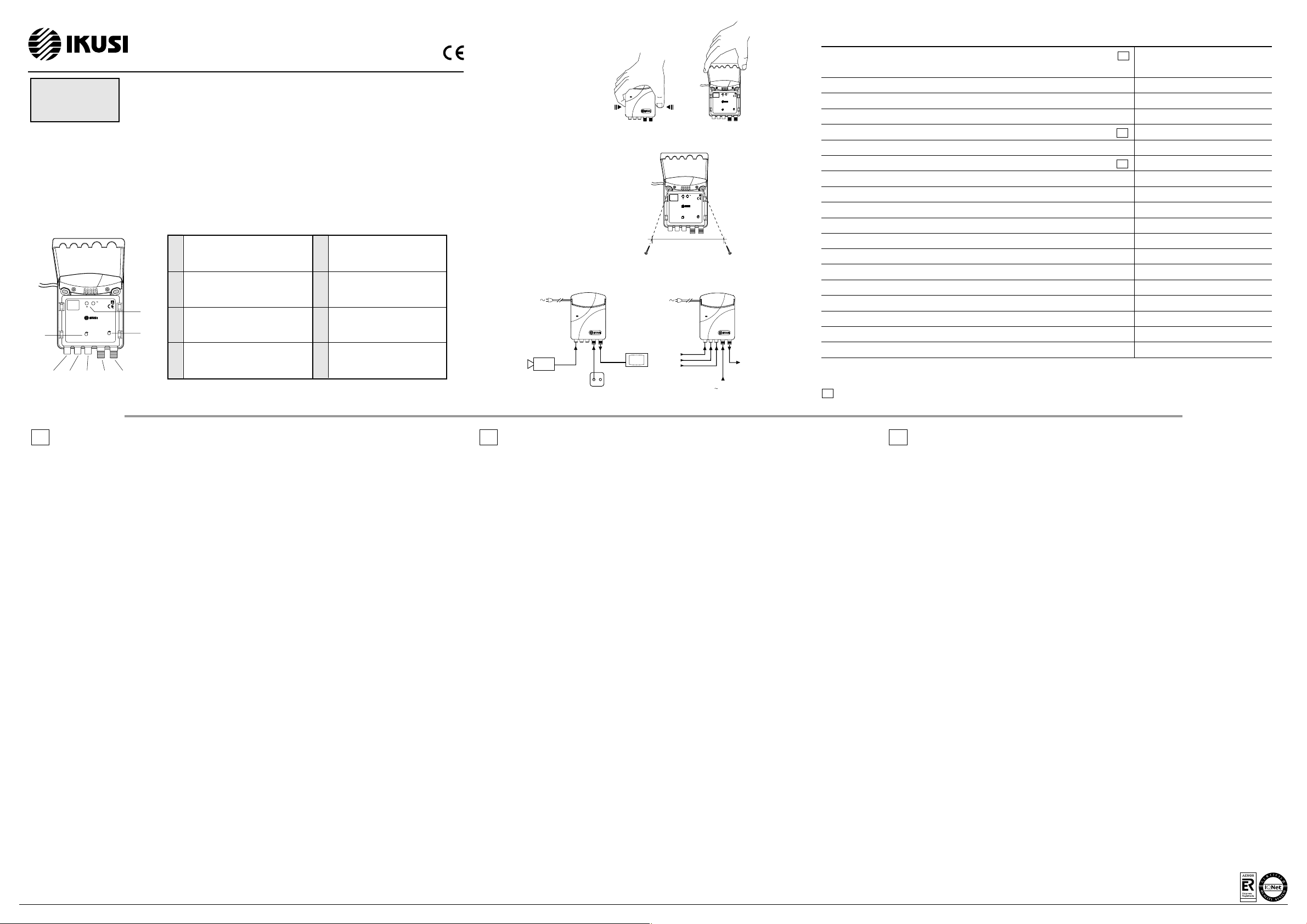
Entrada Vídeo
Video input
Entrée Vidéo
Salida RF al televisor
RF output to TV set
Sortie HF vers le téléviseur
Ajuste modulación audio
Audio modulation setting
Réglage modulation audio
Ajuste nivel salida RF
RF output level setting
Réglage niveau sortie HF
Botones de programación
Programming buttons
Boutons de programmation
1
2
3
6
7
8
Entrada Audio Mono o Audio L
Mono Audio or Audio L input
Entrée Audio Mono ou Audio L
MAW-200
(Ref. 3029)
Entrada Audio R
Audio R input
Entrée Audio R
Acoplamiento señal antena
Antenna signal coupling
Couplage signal antenne
5
4
RCA
type
RCA
type
RCA
type
F
type
F
type
INSTALACION
- Antes de nada leer las instrucciones de seguridad que se indican al dorso de esta hoja.
- Fijar la caja a la pared utilizando dos tirafondos DIN 7971 ∅2,9x19 a través de los orificios interiores señalados en la Fig. 3.
- Pueden instalarse varios moduladores en cascada interconectando las puertas TV OUT y ANT IN con latiguillos coaxiales.
OPERACION
Para cambiar los ajustes del modulador levantar la tapa de plástico tal como se indica en la Fig. 2.
El modulador tiene dos modos de operación :
1. Modo Normal : es el que queda dispuesto tras la conexión del modulador a la red alterna.
2. Modo Ajustes : se cambia a este modo pulsando simultáneamente los botones "+" y "-" ; para retornar al modo Normal
volver a pulsar simultáneamente "+" y "-".
Estando el modulador en modo Normal, el canal de salida se selecciona pulsando el botón "+" ó el "-" (ver atrás tablas
1 a 10). El canal no debe ser adyacente a ninguno de los acoplados a través de la puerta ANT IN.
VALORES DE PARAMETROS POR DEFECTO
1. Canal de salida : E2. (Display : 00
00
0
22
22
2).
2. Desviación de la portadora audio : ±50 kHz (para una señal de entrada de 1 kHz y nivel 775 mV).
3. Sistema B/G ; interportadora audio : 5,5 MHz. (Display: bb
bb
b
55
55
5).
4. Generación de imagen test : OFF. (Display : nn
nn
n
oo
oo
o).
5. Desplazamiento de frecuencia : ninguno. (Display : 00
00
0).
6. Relación de portadoras V/A : 16 dB. (Display : 11
11
1
66
66
6).
7. Señal de salida : ON. (Display : oo
oo
o
nn
nn
n).
Cambio de Parámetros en modo Ajustes :
1. Sistema TV :
a) al pasar al modo Ajustes, el display muestra el sistema TV actual (ver tablas 1-10) ;
b) para cambiar de sistema, pulsar el botón "+" (ver tablas 1-10) ;
c) el modulador queda ajustado al primer canal del sistema seleccionado (ver tablas 1-10); el resto de ajustes
permaneceninvariables.
2. Generación de imagen test :
a) pulsar el botón "-" ;
b) conmutar entre OFF y ON pulsando el botón "+" ; "nn
nn
n
oo
oo
o" significa imagen test OFF y "tt
tt
t
55
55
5" imagen test ON.
3. Desplazamiento de la frecuencia portadora de vídeo :
a) pulsar el botón "-" ;
b) modificar la frecuencia pulsando el botón "+" (ver tabla 11).
4. Cambio de la relación de portadoras imagen/sonido :
a) pulsar el botón "-" ;
b) pulsar el botón "+" para conmutar entre los valores 12 dB y 16 dB.
5. Corte de la señal de salida :
a) pulsar el botón "-" ;
b) conmutar entre RF ON y RF OFF pulsando el botón "+" ; "oo
oo
o
nn
nn
n" significa RF ON y "oo
oo
o
FF
FF
F" RF OFF.
PROTECCIÓN CONTRA ACCESOS NO AUTORIZADOS
Para impedir accesos no autorizados, pulsar simultáneamente los botones "-" y "+" durante unos 5 segundos hasta que en el
display aparezca "LL
LL
L
OO
OO
O". Para retornar a no protección, repetir la acción ; en el display aparece en este caso "UU
UU
U
LL
LL
L".
AJUSTE DE LA DESVIACION DE LA PORTADORA DE SONIDO
La desviación puede ajustarse al valor estándar ±50 kHz siempre que el nivel de la señal audio de entrada esté comprendido
entre 150 y 775 mV. Actuar con un destornillador plano de anchura ≤4mm sobre [6] (Fig. 1).
AJUSTE DEL NIVEL RF DE SALIDA
Actuar con el destornillador sobre [7] (Fig. 1). El margen de ajuste son 20 dB.
INSTALLATION
- First read the safety instruction indicated at the back of this leaf.
- Fix the box on the wall using two DIN 7971
∅
2.9x19 screws through the internal holes indicated in Fig. 3.
- Several modulators can be cascaded by interconnecting the TV OUT and ANT IN ports with coaxial jumpers.
OPERATING
To change the modulator settings, put up the plastic cover as indicated in Fig. 2.
The modulator has two modes of operating :
1. Normal : sets after plug in.
2. Setting : switch on by pressing "+" and "-" buttons simultaneously, switch off and return to Normal mode by
pressing "+" and "-" buttons simultaneously once more.
Being the modulator in Normal mode, the output channel is selected by pressing buttons "+" or "-" (see tables
1 to 10 at back). The output channel must be no adjacent to any of those coupled through the ANT IN port.
DEFAULT PARAMETER VALUES
1. Output channel : E2. (Display : 00
00
0
22
22
2).
2. Audio subcarrier deviation : ±50 kHz (when audio signal is 1 kHz , 775 mV).
3. B/G system ; audio subcarrier 5.5 MHz. (Display: bb
bb
b
55
55
5).
4. Test pattern generator : OFF. (Display : nn
nn
n
oo
oo
o).
5. Frequency shift : none. (Display : 00
00
0).
6. V/A carrier ratio : 16 dB. (Display : 11
11
1
66
66
6).
7. Output signal : ON. (Display : oo
oo
o
nn
nn
n).
Changing of parameters in Setting mode :
1. TV system :
a) after switching Setting mode, the display shows the current TV system (see tables 1-10) ;
b) to change the TV system, press button "+" (see tables 1-10) ;
c) after TV system changing, modulator sets to first channel of selected TV system (see tables 1-10);
other settings remains unchanged.
2. Switch on test pattern generator :
a) press "-" button ;
b) switch between OFF and ON by pressing button "+" ; "nn
nn
n
oo
oo
o"- test pattern OFF, "tt
tt
t
55
55
5"- test pattern ON.
3. Fine tuning of video carrier frequency :
a) press button "-" ;
b) shift video carrier frequency by pressing button "+" (see table 11).
4. Picture/Sound ratio switching :
a) press button "-" ;
b) switch between 12 dB and 16 dB by pressing button "+".
5. Output signal switching :
a) press button "-" ;
b) switch between RF ON and RF OFF by pressing button "+" ; "oo
oo
o
nn
nn
n"- RF on, "oo
oo
o
FF
FF
F"- RF OFF.
PROTECTION FROM UNAUTHORIZED ACCESS
To prevent unauthorized access, press buttons "-" and "+" simultaneously for about 5 seconds until the display show
"LL
LL
L
OO
OO
O". To revert to non-protection, repeat the procedure; the display shows in this case "UU
UU
U
LL
LL
L".
SOUND CARRIER DEVIATION SETTING
The deviation can be set to the ±50 kHz standard value provided that the audio input signal level is between 150 and
775 mV. Operate with a flat,
≤
4mm wide screwdriver on [6] (Fig. 1) .
OUTPUT RF LEVEL ADJUSTMENT
Operate with the screwdriver on [7] (Fig. 1). Adjustment range are 20 dB.
INSTALLATION
- Avant tout lire les instructions de sécurité indiquées au verso de cette feuille.
- Fixer le boîtier au mur moyennant deux vis DIN 7971 ∅2,9x19 à travers les trous intérieurs signalés à la Fig. 3.
- Plusieurs modulateurs peuvent être cascadés en interconnectant les ports TV OUT et ANT IN avec liaisons coaxiaux.
OPÉRATION
Pour changer les réglages du modulateur, lever le couvercle en plastique comme indiqué à la Fig. 2.
Le modulateur a deux modes d'opération :
1. Mode Normal : il est habilité lors du raccordement du modulateur au secteur.
2. Mode Paramétrage : se passe à ce mode en appuyant simultanément sur les boutons "+" et "-" ; pour retourner au
mode Normal, reappuyer simultanément sur "+" et "-".
Étant le modulateur en mode Normal, le canal de sortie est sélectionné en appuyant sur le bouton "+" ou "-" (voir tables
1 à 10 au verso). Le canal de sortie ne doit pas être adjacent à aucun de ceux couplés par le port ANT IN.
VALEURS DE PARAMÈTRES PAR DÉFAUT
1. Canal de sortie : E2. (Écran : 00
00
0
22
22
2).
2. Déviation de la porteuse son : ±50 kHz (pour un signal audio 1 kHz et niveau 775 mV).
3. Norme B/G ; interporteuse son : 5,5 MHz. (Écran: bb
bb
b
55
55
5).
4. Génération d'image test : OFF. (Écran : nn
nn
n
oo
oo
o).
5. Déplacement de fréquence : aucun. (Écran : 00
00
0).
6. Rapport porteuses V/A : 16 dB. (Écran : 11
11
1
66
66
6).
7. Signal de sortie : ON. (Écran : oo
oo
o
nn
nn
n).
Changement de Paramètres en mode Paramétrage :
1. Norme TV :
a) quand se passe au mode Paramétrage, l'écran affiche la norme TV actuelle (voir tables 1-10) ;
b) pour changer la norme, appuyer sur le bouton "+" (voir tables 1-10) ;
c) le modulateur reste réglé au premier canal de la norme sélectionnée (voir tables 1-10); le rest de réglages
restent invariables.
2. Génération d'image test :
a) appuyer sur le bouton "-" ;
b) commuter entre OFF et ON en appuyant sur le bouton "+" ; "nn
nn
n
oo
oo
o" signifie image test OFF et "tt
tt
t
55
55
5" image test ON.
3. Déplacement de la fréquence porteuse image :
a) appuyer sur le bouton "-" ;
b) modifier la fréquence en appuyant sur le bouton "+" (voir table 11).
4. Changement du rapport de porteuses image/son :
a) appuyer sur le bouton "-" ;
b) appuyer sur le bouton "+" pour commuter entre les valeurs 12 dB et 16 dB.
5. Coupure du signal de sortie :
a) appuyer sur le bouton "-" ;
b) commuter entre RF ON et RF OFF en appuyant sur le bouton "+" ; "oo
oo
o
nn
nn
n" signifie RF ON et "oo
oo
o
FF
FF
F" RF OFF.
PROTECTION CONTRE LES ACCÈS NON AUTORISÉS
Pour empêcher les accès non autorisés, appuyer simultanément sur les boutons "-" et "+" pendant 5 secondes à peu près
jusqu'à ce que l'écran affiche "LL
LL
L
OO
OO
O". Pour retourner à non-protection répéter l'action ; l'écran affiche en ce cas "UU
UU
U
LL
LL
L".
RÉGLAGE DE DÉVIATION DE LA PORTEUSE SON
La déviation peut être réglée à la valeur standard ±50 kHz pourvu que le signal audio d'entrée est compris entre 150 et
775 mV. Opérer avec un tournevis plat de largeur ≤4mm sur [6] (Fig. 1).
RÉGLAGE DU NIVEAU HF DE SORTIE
Opérer avec le tournevis sur [7] (Fig. 1). La plage de réglage sont 20 dB.
6
12345
7
8
CHANNEL
+
VIDEO AUDIO L AUDIO R ANT IN TV OUT
AUDIO OUT
AUDIO MONO
MAW-200
Ref.
3029
Multistandard TV Modulator
230-240V/50Hz/3W
CHANNEL
+
VIDEO AUDIO L AUDIO R ANT IN TV OUT
AUDIO OUT
AUDIO MONO
MAW-200
Ref.
3029
Multistandard TV Modulator
230-240V/50Hz/3W
64 mm
CHANNEL
+
VIDEO AUDIO L AUDIO R ANT IN TV OUT
AUDIO OUT
AUDIO MONO
MAW-200
Ref.
3029
Multistandard TV Modulator
230-240V/50Hz/3W
Fijación a la pared
Wall fixing
Fixation au mur
DESCRIPCION
El modulador MAW-200 genera canales TV doble banda lateral y sonido mono de los sistemas B, G, D, K, H, I, L, M, N. Al dispositivo
se le pueden conectar fuentes de audio estéreo: las señales L y R son sumadas por el propio modulador.
DESCRIPTION
The MAW-200 modulator generates double sideband, mono sound TV channels of the systems B, G, D, K, H, I, L, M, N. Stereo sound
sources can be connected to the device: the L and R signals are sumed by the modulator itself.
DESCRIPTION
Le modulateur MAW-200 génére des canaux TV double bande latérale et son mono des normes B, G, D, K, H, I, L, M, N. Au dispositif
on peut raccorder des sources audio stéréo : les signaux L et R sont sommés par le modulateur lui-même.
Canales de salida / Output channels / Canaux de sortie
(Sistemas TV / TV Systems / Normes TV : B , G , D , K , H , I , L , M , N)
Espectro canal salida / Output channel spectrum / Spectre canal sortie
Modo operación audio / Audio operation mode / Mode opération audio
Banda de acoplo antena / Coupling antenna bande / Bande de couplage antenne (ANT IN)
Desplazamiento port. vídeo / Fine tuning of video carrier / Déplacement port. vidéo
Nivel ajustable de salida / Adjustable output level / Niveau de sortie réglable
Relación port. conmutable / Switchable carrier ratio / Rapport porteuses commutable
Nivel de entrada vídeo / Video input level / Niveau d'entrée vidéo
Impedancia de vídeo / Video impedance / Impédance vidéo
Profundidad modulación vídeo / Video modulation depth / Profondeur modulation vidéo
Nivel de entrada audio / Audio input level / Niveau d'entrée audio
Impedancia de audio / Audio impedance / Impédance audio
Desviación audio * / Audio peak deviation * / Déviation pic audio *
Preénfasis audio / Audio pre-emphasis / Pré-accentuation audio
Relación S/N ponderada / Weighted S/N ratio / Rapport S/N pondéré
Pérdida acoplamiento señal antena / Antenna coupling loss / Perte couplage antenne
Tensión de red / Mains voltage / Tension secteur
Consumo de potencia / Consumption / Consommation
Temperatura funcionamiento / Operating temperature / Température fonctionnement
ESPECIFICACIONES TECNICAS / TECHNICAL SPECIFICATIONS / SPÉCIFICATIONS TECHNIQUES
ver atrás tablas 1-10
see tables 1-10 at back
voir tables 1-10 au verso
DBL / DSB / DBL
Mono
47 - 2150 MHz
max ±2.25 MHz (0.25 MHz pas/steps)
65 - 85 dBμμ
μμ
μV
12 ±3 / 16 ±3 dB
0.9 ... 1.1 Vpp
75 ΩΩ
ΩΩ
Ω
81 %
150 ... 775 mV
10 kΩΩ
ΩΩ
Ω
± 50 kHz
50 μμ
μμ
μs
> 55 dB
< 1.5 dB (TV) ,, < 2.7 dB (SAT)
230-240 (±10%) VAC
3 W
-10 ... +55 °C
pr.
pr.
pr.
- programable / programmable / programmable
* La desviación estándar ±50 kHz puede establecerse para cualquier nivel audio de entrada comprendido entre 150 y 775 mV
*The standard deviation ±50 kHz can be established for any input audio level between 150 and 775 mV
* La déviation standard ±50 kHz peut être établie pour n'importe quel niveau audio d'entrée compris entre 150 et 775 mV
Fig. 3
Fig. 1
ES
IKUSI — Ángel Iglesias, S.A.
Paseo Miramón, 170 - 20009 San Sebastián - SPAIN Tel.: +34 943 44 88 00 Fax: +34 943 44 88 11 www.ikusi.com
ER-0149/1996
EN FR
Fig. 2
pr.
Ejemplos de aplicación
Application examples
Exemples d'application
TV
base de to a
TV outlet
prise TV
cá ara de vigilancia
surveillance camera
ca éra de vigilance
Apertura de la tapa
Opening the cover
Ouverture du couvercle
video
audio R
ultichannel signal
( 85 dBmV)
n+1 channels
n channels
audio L


