1.1
Features
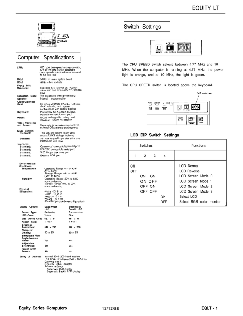
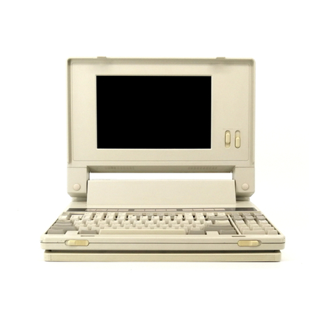
The OX-1 0 is an all business computer system.
It
consists
of
a
Z80A-compatible
CPU,
a memory
of
256
KB
maximum,
two
floppy disk drivers
of
double-sided, double-density,
5-1/4"
disks, and a
12"
full-graphic
CRT
display
with
a resolution
of
640
by
400
dots.
The standard configuration includes a programmable timer, Centronics-compatible
printer
interface,
RS-232C interface, C-MOS RAM backed up
by
battery, clock and calendar, and separate keyboard.
It
has five card slots
which
permit installation
of
optional cards
as
required.
Optional cards available include character generators
of
varying fonts, IEEE-488 interface, optical fib-
er interface,
color
CRT
interface, and pulse transformer interface.
1.2
Hardware
configuration
1.2.1 General
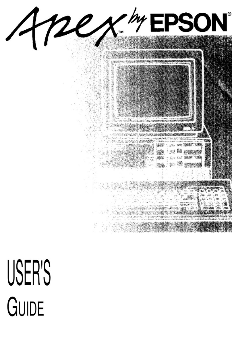
The OX-1 0 is composed of three units:
the
main system unit,
the
keyboard unit, and
the
monitor
unit.
The main system unit,
the
heart
of
the
QX-10
system, includes the main
circuit
board, sub
circuit
board,
power
supply,
two
5-1/4"
floppy
disk
drives developed
by
Epson, and five slots
permitting
in-
stallation
of
optional cards.
The keyboard
unit
is connected
to
the main system
unit
with
a curled cord
through
which
signals may
be transmitted in any direction.
The standard
monitor
unit
is a
12"
high resolution green
monitor
capable
of
displaying
bit
images.
1.2.2
Hardware
Main system
CPU
Memory
Clock
Speaker
Interfaces
DMA
Interrupt levels
Counter/timer
FDD
Card slots
Monitor
Keyboard
.uPD780AC-1
(Z80A
compatible, 4 MHz)
RAM :
256
KB
(maximum
on
main board)
VIDEO RAM :
128
KB
(maximum on
CRT
board)
C-MOS RAM : 2
KB
(standard, backed up by battery)
EPROM :
2/4/8
K8
(for
IPL)
C-MOS real-time clock (backed up by battery)
Permanent magnet speaker
Printer interface (Centronics-compatible)
RS-232C communications interface
7 channels
15
6 channels
5-1/4"
FDD
x 2
320
KB x 2 drives
48
TPI, double sided & double density
5
1
2"
green
monitor
640
x
400
dots
ASCII, HASCI
1-1

