EPTA EIS 165.3 N/P KW User manual

SERVICE MANUAL EIS 165.3 N/P KW (short version) inglese
Autori: Serralunga M.
14/10/2021
1
NO COPYING IN ANY FORM WITHOUT WRITTEN PERMISSION FROM EPTA QUALITY MANAGEMENT
EIS 165.3 N/P KW
Service Manual
COQ
EIS165.3N/PKWServiceManual(shortversion)

SERVICE MANUAL EIS 165.3 N/P KW (short version) inglese
Autori: Serralunga M. 14/10/2021
2
NO COPYING IN ANY FORM WITHOUT WRITTEN PERMISSION FROM EPTA QUALITY MANAGEMENT
TABLE OF CONTENTS
1. AMOUNT OF REFRIGERANT IN THE EQUIPMENT 3
2. REFRIGERATION SCHEMATICS FOR THE EQUIPMENT 4
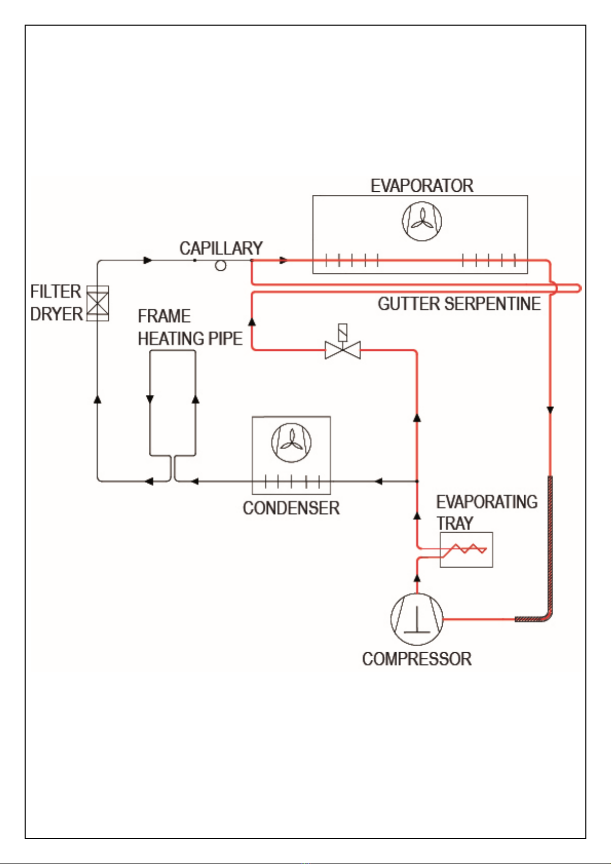
2.1. REFRIGERATION DIAGRAM FOR EIS 165.3 N/P KW 4
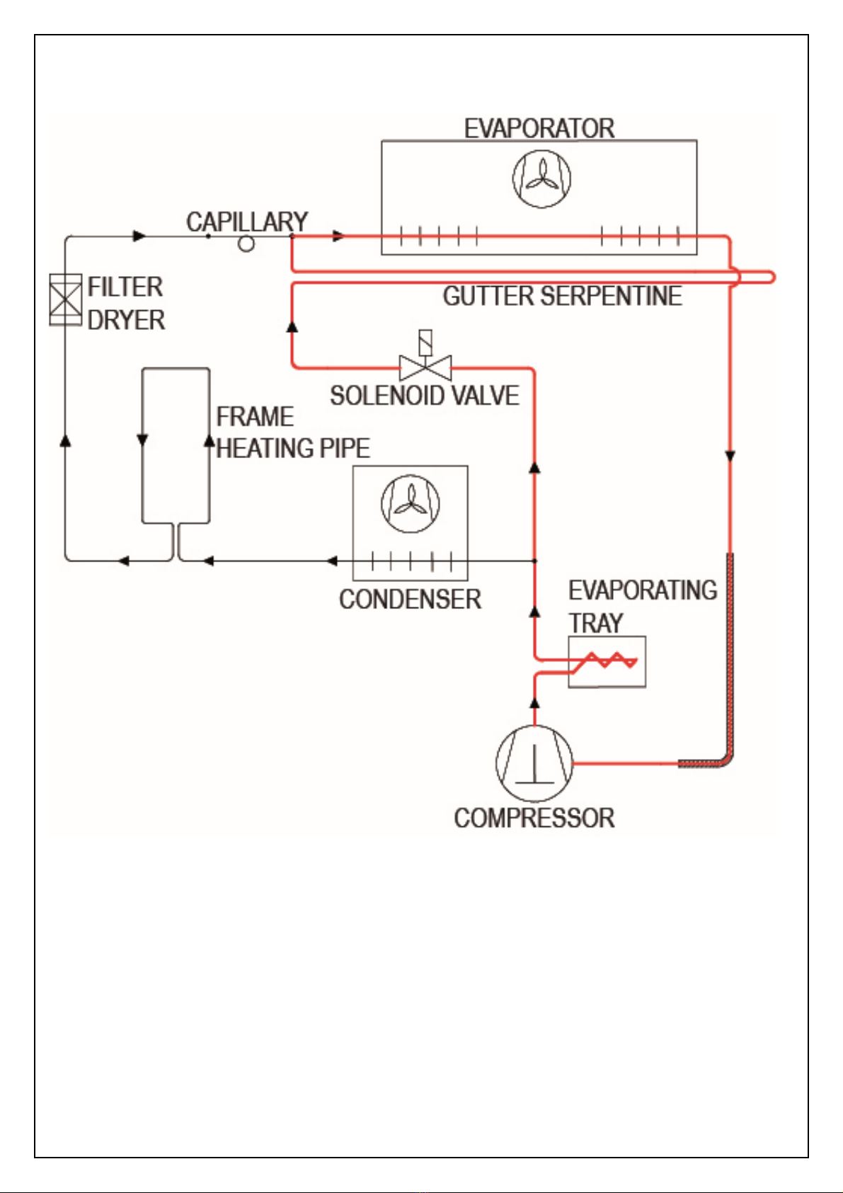
2.2. REFRIGERATION DIAGRAM FOR DEFROST CYRCLE EIS 165.3 N/P KW 6
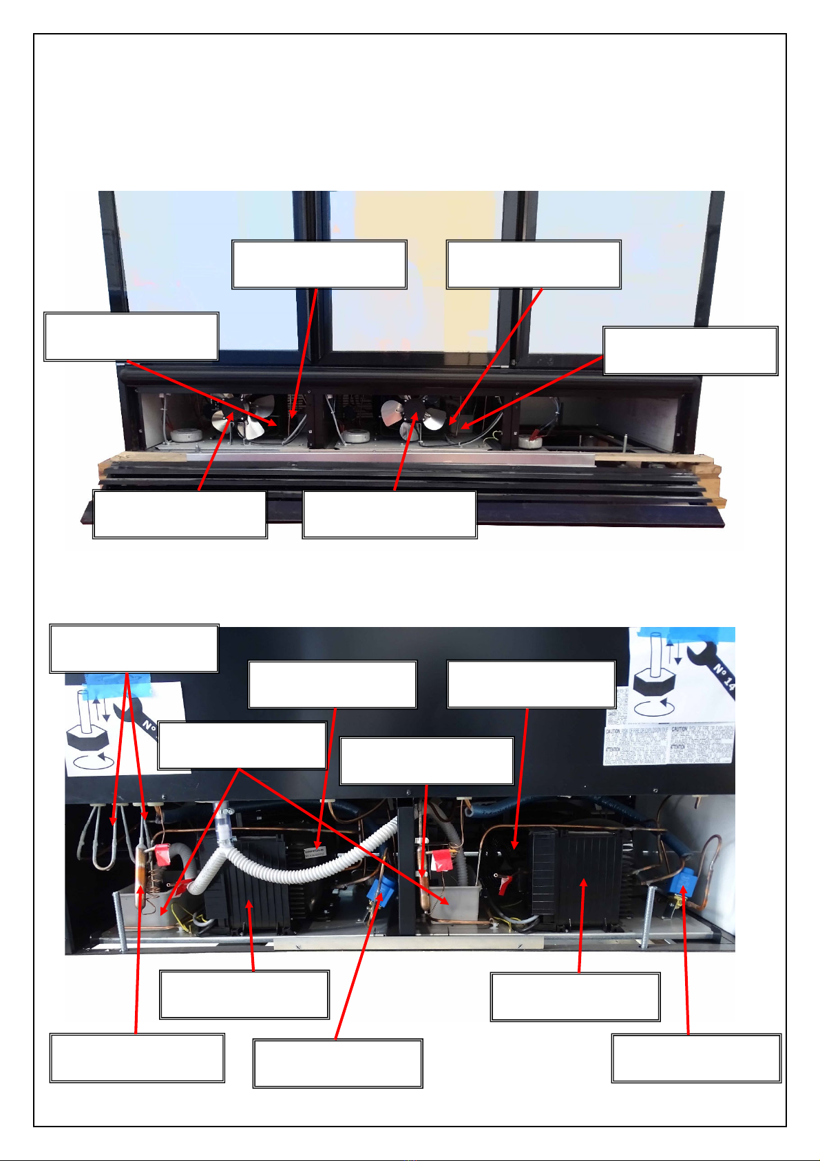
2.3. VIEW OF MOTOR COMPARTMENT – EIS 165.3 N/P KW 8
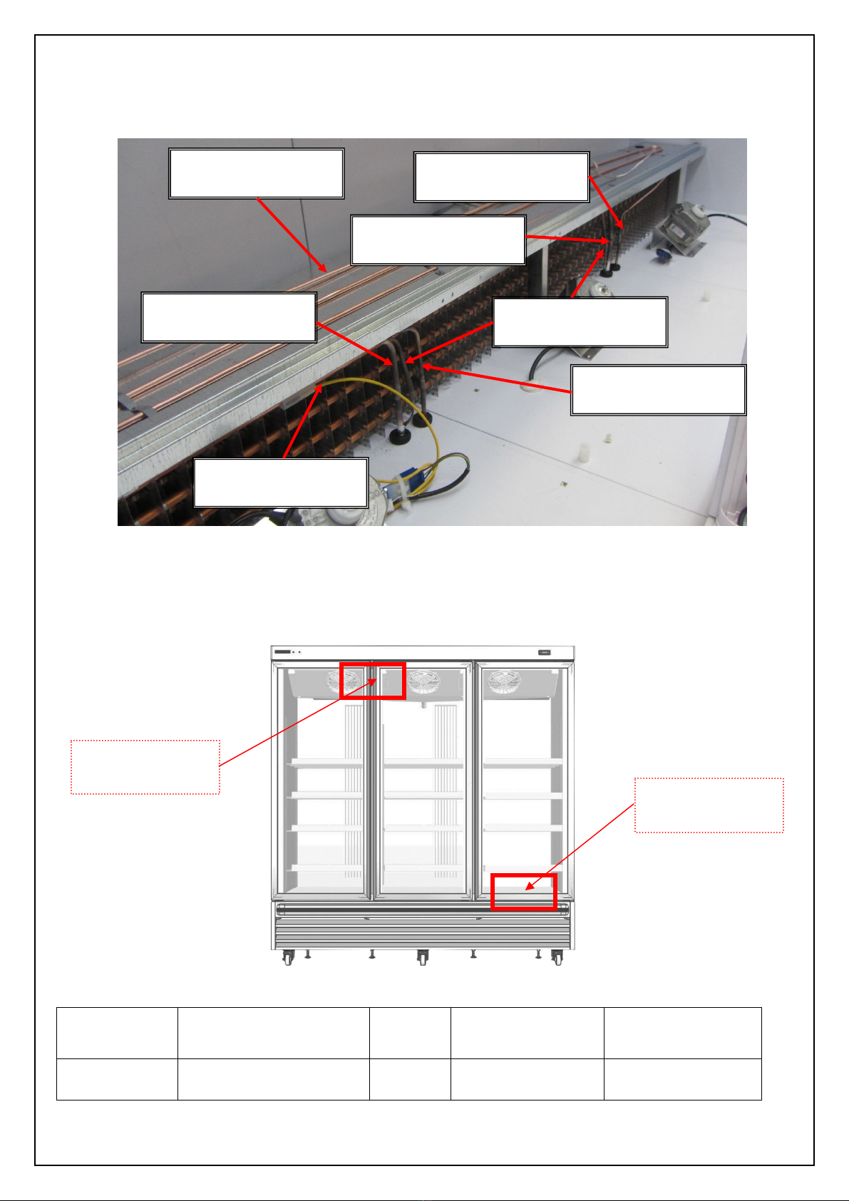
2.4. VIEW OF THE EVAPORATOR COMPARTMENT - EIS 165.3 N/P KW 9
3. POSITION OF PROBE IN THE CABINET 9
4. ALARMS FOR EIS 165.3 N/P KW (Dixell Controller) 10
5. REPLACEMENT OF COMPONENTS 10
5.1. SAFE OPERATING PROCEDURES FOR REFRIGERAION UNIT USING R290 10
5.2. PROTECTION TOOLS AND DEVICES FOR SERVICEMENT 11
5.3. HOW TO EMPTY THE COOLING CIRCUIT AND PROVE IT BEFORE SERVICING 14
5.4. COMPRESSOR REPLACEMENT 15
5.5. UNSOLDER COPPER PIPE TUBE 15
5.6. COMPRESSOR REMOVING 16
5.7. NEW COMPRESSOR INSERTION 16
5.8. HIGH PRESSURE PIPE CLOSING 16
5.9. REFRIGERANT GAS CHARGING AND THERMODYNAMIC CIRCUIT CLOSING 18
5.10. CHECK THE CORRECT CLOSING OF THERMODYNAMIC CIRCUIT 20
5.11. REPLACEMENT OF CONDENSER MOTOR FAN 21
5.12. REPLACEMENT OF EVAPORATOR MOTOR FAN 21
5.13. REPLACEMENT OF POWER CORD 22
5.14. REPLACEMENT OF SOLENOID VAVE 22
5.15. REPLACEMENT OF ELECTRONIC CONTROLLER 23
5.16. REPLACEMENT OF LED BAR 23
5.17. REPLACEMENT OF TEMPERATURE SWITCH 23
5.18. REPLACEMENT OF TEMPERATURE YELLOW LIGHTS 24
5.19. REPLACEMENT OF DOOR AND DOOR GASKET 24
5.20. REPLACEMENT OF PROBS 30
5.21. REPLACEMENT OF DEFROST HEATER 31
5.22. REPLACEMENT OF DOOR HANDLE 31
5.23. REPLACEMENT OF FEET CASTORSLACEMENT OF SHELF RACK 32
5.24. REPLACEMENT OF SHELF RACK 33
6.MAINCABINETFUNCTIONS 34
6.1. DISPLAY UNIT AND MAIN PARAMETERS 34
6.2.USEOFLEDS 34
6.3. HOW TO CHANGE A PARAMETER VALUE 34
6.4. CONTROLLER PARAMETERS 35
6.5. TEMPERATURE SETTING 36
7.WIRINGDIAGRAM 37
7.1. WIRING DIAGRAM LEGEND 37
7.2. WIRING DIAGRAM 38
8. COMMON PROBLEM AND TROUBLESHOOTING 39
8.1. UNIT NOT IN TEMPERATURE 39
8.2. NOISY UNIT 41
8.3. PRESENCE OF WATER ON THE FLOOR OR ABNORMAL ICE INSIDE TANK 41
8.4. POSSIBLE PROBLEMS AFTER CIRCUIT REWORKS 43
8.5. INVERTER TROUBLESHOOTING 44

SERVICE MANUAL EIS 165.3 N/P KW (short version) inglese
Autori: Serralunga M.
14/10/2021
3
NO COPYING IN ANY FORM WITHOUT WRITTEN PERMISSION FROM EPTA QUALITY MANAGEMENT
1.
AMOUNT OF REFRIGERANT IN THE EQUIPMENT
The most prominent feature of the EIS 165.3 N/P KW versions is that they use a natural gas: propane
(R290).
MODEL
AMOUNT OF
PROPANE*
[
g
rams]
EIS 165.3 N/P KW
270
(*) The propane refrigerant R290 to be used must be technical-gas rated, with purity grade above 99,5%.
PROPANE IS HEAVIER THAN AIR, WHICH MEANS THAT IT WILL
TEND TO CONCENTRATE NEAR THE FLOOR OF THE ROOM.
The flammability limit percentage (in a volume of air) is between 2,2% and 9,2% (at 25°C and 1bar).
In mass terms:
If the entire amount of refrigerant is released in the chest of a EIS 165.3 N/P KW, this would be a
flammability zone event.
39g/m3177g/m3
Striking will not cause
flames
Striking will not cause
flames
0% Striking will not cause
flames
100%

SERVICE MANUAL EIS 165.3 N/P KW (short version) inglese
Autori: Serralunga M. 14/10/2021
4
NO COPYING IN ANY FORM WITHOUT WRITTEN PERMISSION FROM EPTA QUALITY MANAGEMENT
2. REFRIGERATION SCHEMATICS FOR THE EQUIPMENT
2.1
REFRIGERATION DIAGRAM FOR THE COOLING CYCLE
EIS 165.3 N/P KW
GROUP 1 – LEFT SIDE – REFRIGERANT CHARGE 130g
Point into which
nitrogen needs to be
blown to remove
propane from the
pipework.

SERVICE MANUAL EIS 165.3 N/P KW (short version) inglese
Autori: Serralunga M. 14/10/2021
5
NO COPYING IN ANY FORM WITHOUT WRITTEN PERMISSION FROM EPTA QUALITY MANAGEMENT
GROUP 2 – CENTRAL SIDE – REFRIGERANT CHARGE 140 g
Point into which
nitrogen needs to be
blown to remove
propane from the
pipework.

SERVICE MANUAL EIS 165.3 N/P KW (short version) inglese
Autori: Serralunga M. 14/10/2021
6
NO COPYING IN ANY FORM WITHOUT WRITTEN PERMISSION FROM EPTA QUALITY MANAGEMENT
2.2
REFRIGERATION DIAGRAM FOR THE DEFROST CYCLE -
EIS 165.3 N/P KW
The open solenoid valve runs gas through the drip trough and then sends it straight to the evaporator.
GROUP 1

SERVICE MANUAL EIS 165.3 N/P KW (short version) inglese
Autori: Serralunga M. 14/10/2021
7
NO COPYING IN ANY FORM WITHOUT WRITTEN PERMISSION FROM EPTA QUALITY MANAGEMENT
GROUP 2

SERVICE MANUAL EIS 165.3 N/P KW (short version) inglese
Autori: Serralunga M. 14/10/2021
8
NO COPYING IN ANY FORM WITHOUT WRITTEN PERMISSION FROM EPTA QUALITY MANAGEMENT
2.3
VIEW OF THE MOTOR COMPARTMENT AND RELEVANT PIPEWORK
EIS 165.3 N/P KW
VIEW OF MOTOR COMPARTMENT – FRONT SIDE
VIEW OF MOTOR COMPARTMENT – REAR SIDE
CONDENSER MOTOR
FAN
CONDENSER MOTOR
FAN
DISCHARGE LINE
COMPRESSOR
SOLENOID VALVE
FRAME HEATING PIPE
CONDENSER
DISCHARGE LINE
CONDENSER
COMPRESSOR
INVERTER INVERTER
SOLENOID VALVE
FILTER DRYER
FILTER DRYER
EVAPORATING WATER
TRAY

SERVICE MANUAL EIS 165.3 N/P KW (short version) inglese
Autori: Serralunga M. 14/10/2021
9
NO COPYING IN ANY FORM WITHOUT WRITTEN PERMISSION FROM EPTA QUALITY MANAGEMENT
2.4
VIEW OF THE EVAPORATOR COMPARTMENT AND RELEVANT
PIPEWORK - EIS 165.3 N/P KW
3. POSITION OF PROBES IN THE CABINET
There are two probes in the EIS 165 N/P KW model.
Model Position of probe Probe
Colour Function Probe Epta code
EIS 165 N/P KW Evaporator
Tank – motor compartment
Yellow
Grey
Defrost
Display - Thermostat
I0205786
I0205805
GUTTER SERPENTINE
GUTTER SEPRENTINE –
SOLENOID VALVE
SUNCTION PIPE –
EVAPORATOR OUTLET
CAPILLARY –
EVAPORATOR INPUT
DEFROST PROBE
GUTTER SEPRENTINE –
SOLENOID VALVE
SUNCTION PIPE –
EVAPORATOR OUTLET
Position of probe
touching
Position of probe
touching

SERVICE MANUAL EIS 165.3 N/P KW (short version) inglese
Autori: Serralunga M.
14/10/2021
10
NO COPYING IN ANY FORM WITHOUT WRITTEN PERMISSION FROM EPTA QUALITY MANAGEMENT
4. ALARMS FOR EIS 165.3 N/P KW (Dixell Contreller)
ALARM CAUSE
OUTPUTS
“P1”
Temperature probe damage “Con” and “COF” compressor outputs.
“P2”
Evaporator probe damage Timed defrosting
“HA”
Maximum temperature alarm Outputs unchanged
“LA”
Minimum temperature alarm Outputs unchanged
Probe alarms P1 and P2 start some seconds after the fault in the related probe; they automatically stop
some seconds after the probe restarts normal operation. Check connections before replacing the probe.
Temperature alarms HA and LA automatically stop as soon as the temperature returns to normal values.
5. REPLACEMENT OF COMPONENTS AND REPAIR OF A LEAK
The instructions below, which involve opening the refrigerating circuit, must be performed in a
place with sufficient air circulation and at any rate not in the sales area.
5.1
SAFE OPERATING PROCEDURES FOR REFRIGERATION UNITS
USING R290
Before carrying out any kind of maintenance operation on the refrigerator, make sure that the
machine is disconnected from power (unplugged).
R290 (Propane CH3CH2CH3) is a flammable natural refrigerant (Hydrocarbon HC) having
lower explosive limit ( LEL %V/V) = 1.7.
The very low quantity of refrigerant used and the safe design (possible ignition sources
enclosed in a metal box, far from the potential explosive areas) make this unit totally safe in
use. Caution must be used during servicing and with this respect it is essential to understand
the basic concept of flammability.
Three ingredients are needed for a fire: a fuel at the right concentration, a supply of oxygen
normally from air, and a source of ignition. The common way of illustrating this is by means of
the fire triangle.
If you control these components, for example, by eliminating at least one but preferably two
of these, fire can be prevented.
In order to achieve this, three general guidelines should be followed during servicing:
F1. Containment of the substance;
F2. Avoidance of ignition sources;
F3. Use of ventilation.

SERVICE MANUAL EIS 165.3 N/P KW (short version) inglese
Autori: Serralunga M. 14/10/2021
11
NO COPYING IN ANY FORM WITHOUT WRITTEN PERMISSION FROM EPTA QUALITY MANAGEMENT
F1. Containment
The flammable substances must be kept within a suitably designed and constructed
“container”, be it a suitable cylinder or a refrigeration system. If the substance leaks, it should
be prevented from spreading to other areas.
F2. Ignition sources
Ensure that all the obvious and unobvious ignition sources have been removed from the
equipment and handling areas. Ignition sources can vary greatly and these sources may
include sparks from electrical equipment or welding and cutting tools, hot surfaces, open
flames from heating equipment, smoking materials, etc.
F3. Ventilation
There should be adequate airflow where flammable substances are stored and used.
Good ventilation will mean that any vapor arising from a leak or a release will be rapidly
dispersed. In case one of the components of the refrigerating hermetic circuit (compressor,
dryer, condenser, evaporator, capillary, refrigerant) needs to be serviced, the basic safe
guideline must be always followed:
NEVER USE FLAMES OR HEAT SOURCES IF
FLAMMABLE REFRIGERANT IS PRESENT
INSIDE THE REFRIGERATING CIRCUIT
Flames can be used only when there is evidence that no flammable substance is still inside the
circuit or the circuits; IN CASE OF MULTIPLE CIRCUITS NONE OF THEM MUST CONTAIN
FLAMMABLE SUBSTANCES in case heat sources are to be used: all circuits need to be emptied
and absence of flammable substances must be proved.
IMPORTANT
Provisions for all jobs involving the opening of the refrigerating circuit:
‐SHUT DOWN THE POWER SUPPLY
‐MANDATORILY WEAR GLOVES AND GLASSES
‐DO NOT WORK WITH OPEN FLAMES BEFORE THE PIPEWORK HAS BEEN CUT!
‐REMOVE ALL SPARK SOURCES FROM THE WORK AREA (LIGHTERS, LAMPS,
CIGARETTES).
5.2
PROTECTION TOOLS AND DEVICES FOR SERVICING
Protection tools:

SERVICE MANUAL EIS 165.3 N/P KW (short version) inglese
Autori: Serralunga M. 14/10/2021
12
NO COPYING IN ANY FORM WITHOUT WRITTEN PERMISSION FROM EPTA QUALITY MANAGEMENT
Devices for servicemen:
LOWPRESSURE
SUCTIONGAUGE
REFRIGERANTPINCH
OFFTOOL
ELECTRONICLEAK
DETECTOR
REFRIGERAT
JUNCTIONS
LOCKRINGJOINT
PLIER
LOCKRINGJOINT
WITHCLOSEDSIDE
REFRIGERANTGAS
BOTTLE
NITROGENGAS
BOTTLE

SERVICE MANUAL EIS 165.3 N/P KW (short version) inglese
Autori: Serralunga M. 14/10/2021
13
NO COPYING IN ANY FORM WITHOUT WRITTEN PERMISSION FROM EPTA QUALITY MANAGEMENT
REFRIGERANTSCALE
VACUUMPUMP
LOKPREPSEALANT
ORBITALCUTTER
SCREWDRIVER
WRENCHn°10

SERVICE MANUAL EIS 165.3 N/P KW (short version) inglese
Autori: Serralunga M. 14/10/2021
14
NO COPYING IN ANY FORM WITHOUT WRITTEN PERMISSION FROM EPTA QUALITY MANAGEMENT
5.3
HOW TO EMPTY THE COOLING CIRCUIT AND PROVE IT BEFORE
SERVICING
The refrigerating unit has a double servicing pipe, on the low (A) and on the high (B) pressure sides:
in order to totally remove the flammable refrigerant from the refrigerating circuit both pipes are to be
opened by using an orbital cutter (C).
Cut the capillary tube (D) exiting the filter dryer.
When the inside pressure is equalized with the ambient pressure, blow nitrogen at 10 bars in the circuit
through the service pipe on high pressure side (B) and check that it flows out through the other service
pipe on the low pressure side; continue to blow nitrogen for at least 5 minutes.
At the end of this procedure NO FLAMMABLE REFRIGERANT CAN REMAIN INSIDE THE
CIRCUIT IN SUCH A QUANTITY TO BE DANGEROUS WHEN FLAMES OR HEAT SOURCES
ARE USED.
n
i
t
r
o
g
e
n
B
A
C
D
Also cut the pipe
entering the filter
and replace the
filter dryer with a
new one.

SERVICE MANUAL EIS 165.3 N/P KW (short version) inglese
Autori: Serralunga M. 14/10/2021
15
NO COPYING IN ANY FORM WITHOUT WRITTEN PERMISSION FROM EPTA QUALITY MANAGEMENT
5.4
COMPRESSOR REPLACEMENT
5.5
UNSOLDER COPPER PIPE TUBE
After being that no more refrigerant gas is inside the thermodynamic circuit, unsolder from
compressor the charge pipe (A), the suction pipe (1) and the discharge pipe (2).
EIS 165.3 N/P KW
Epta code: 45911034 (2 pc)
Model: SECOP NLV12.6CN 198-254V 50/60HZ
Epta code for filter: I0145073 (2 Pc)
Model: Filter gr 15 øi 5-3.2
Note: when the compressor is replaced the filter drier must be replaced too
A
1
2

SERVICE MANUAL EIS 165.3 N/P KW (short version) inglese
Autori: Serralunga M. 14/10/2021
16
NO COPYING IN ANY FORM WITHOUT WRITTEN PERMISSION FROM EPTA QUALITY MANAGEMENT
5.6
COMPRESSOR REMOVING
Unscrew the 4 screws of compressor by using the wrench n°10.
Using the screwdriver for unscrew the compressor box (if present).
5.7
NEW COMPRESSOR INSERTION
By using 4 screws fix the new compressor to motor base (wrench n°10) and then screw compressor box
(screwdriver).
After secure the compressor to the base, solder the discharge and suction piping, then also solder the
capillary tube onto the filter after cutting it diagonally and fitting it in by max. 3cm. Solder the pipe exiting
the condenser to the filter inlet. When the circuit is closed, charge the circuit with helium/nitrogen up to a
pressure of 8 bar. Close the circuit to hold the pressure in, then search for circuit leaks using a leak
detector. Adjust the sensitivity of the electronic leak detector (when available) and test each and every
soldering. The sensor will beep when a leak is found. Connect the vacuum pump to the compressor and
filter service intakes and hold the vacuum for at least 30-40minutes (value depending on pump features).
The vacuum degree to be achieved is below 15 Pa or 0,15 mbar .
WARNING! Wrong vacuum execution may cause problems on the refrigerator performance.
5.8
HIGH PRESSURE PIPE CLOSING
After 30-40 minut of vacuum operation, disconnect the vacuum machine only on the high
pressure pipe (B).
Take the plier (3) and pinch the high pressure pipe (B), then remove refrigerant junction.
Picture example
of motor
compartment
3
B

SERVICE MANUAL EIS 165.3 N/P KW (short version) inglese
Autori: Serralunga M. 14/10/2021
17
NO COPYING IN ANY FORM WITHOUT WRITTEN PERMISSION FROM EPTA QUALITY MANAGEMENT
Put a drop of Lokprep sealant (4) on the high pressure pipe (B).
Insert lockring joint (5) on the high pressure pipe (B). Rotate the joint (5) for correctly
distribute the sealant (4).
By using the lockring plier (6) fix joint (5) on the copper pipe (B).
4
B
1
5B
6
5
B

SERVICE MANUAL EIS 165.3 N/P KW (short version) inglese
Autori: Serralunga M. 14/10/2021
18
NO COPYING IN ANY FORM WITHOUT WRITTEN PERMISSION FROM EPTA QUALITY MANAGEMENT
5.9
REFRIGERANT GAS CHARGING AND THERMODYNAMIC CIRCUIT
CLOSING.
Check the refrigerant charge on the data label inside the cabinet.
Using a refrigerant scale (7), verify the quantity of refrigerant gas in the gas bottle (8).
REFRIGERNAT CHARGE:
Lateral Side Circuit: Refrigerant Charge 130 g
Central Side Circuit: Refrigerant Charge 140 g
Disconnect the vacuum machine from the low pressure pipe (A); connect the gas bottle
(8) to the circuit.
WARNING! in order to avoid damages on the thermodynamic system or danger for
technical assistant; be sure to have connected the gas bottle to the refrigerator circuit.
The refrigerator must be ON for 5-6 minutes, then disconnect the refrigerator from current.
8
7
R
2
9
0

SERVICE MANUAL EIS 165.3 N/P KW (short version) inglese
Autori: Serralunga M. 14/10/2021
19
NO COPYING IN ANY FORM WITHOUT WRITTEN PERMISSION FROM EPTA QUALITY MANAGEMENT
Take the plier (3) and pinch the low pressure pipe (A), then remove refrigerant junction.
Put a drop of Lokprep sealant (4) on the low pressure pipe (A).
Insert lockring joint (5) on the low pressure pipe (A). Rotate the joint (5) for correctly
distribute the sealant (4).
3
A
4
A
1
5A

SERVICE MANUAL EIS 165.3 N/P KW (short version) inglese
Autori: Serralunga M. 14/10/2021
20
NO COPYING IN ANY FORM WITHOUT WRITTEN PERMISSION FROM EPTA QUALITY MANAGEMENT
By using the lockring plier (6) fix joint (5) on the copper pipe (A).
5.10
CHECK THE CORRECT CLOSING OF THERMODYNAMIC CIRCUIT
Use the electronic leak detector (9) in order to check if leak of gas are present.
‐End of high pressure pipe (lockring joint).
‐End of low pressure pipe (lokring joint).
‐Suction pipe welding.
‐Charge pipe welding.
‐Discharge pipe welding.
6
5
A
Table of contents
Other EPTA Display Case manuals