Equalizer Systems Auto Level Operating and installation instructions

Basic Trouble Shooting for Auto-Level
For Systems Using Current Controller/Keypad
Control Panel (Keypad)
Often times the keypad is condemned as defective when it is not. The keypad is nothing more
than switches and lights. The keypad communicates with the controller (black box mounted
under and center of vehicle). More often than not, a complaint on the keypad is an issue with the
controller or another item- such as wiring. See the topics below for help in determining the true
issue. Also note that some applications will not allow extension of the jacks if the key is in the
wrong position. Most systems will not allow the extension of the jacks if the key is in the on
position. However, there are some that will only allow extension if the key is on. Also there is a
park brake disable that will deny extension if the park brake is not applied. This park brake
disable is not connected in all applications.
Keypad will not power up
The keypad should power up with the key in the on or off position. There is a power indicator
light next to the power switch that should come on when the power button is pressed. If it does
not then there is a power supply issue or the keypad and/or controller is defective. There could
also be an issue with the harness that connects the keypad to the controller. The keypad receives
its power from (and is turned on) by the controller. There are 4 wires that connect the keypad to
the controller. Often times the keypad will be condemned as it has power and ground measured
to it at the red and black wires. Measure for voltage (there should be voltage across these two
wires regardless of the keypad power button/light or ignition key status) across the red
(12VDC+) and black (12VDC-). The other two wires (green and brown) are data communication
between the keypad and the controller. Do not attempt to measure to or across these two wires
for voltage. Appling voltage + or – to the green or brown wire could damage the keypad or
controller. They may be checked for continuity end to end if the connector is unplugged from the
keypad and the controller.

More often than not, a keypad that will not power up is due to a defective controller -or no power
or ground to the controller. If there is power and ground to the controller (measure with a digital
volt meter at the red and black wires feeding to the controller from the pump), then the controller
is most likely at fault. There will be no way for a tech in the field to determine this for sure (other
than replacement) so both a controller and a keypad should be ordered, if the wiring is found to
be correct.
Keypad powers up then shuts down when other buttons are pressed
This is known as a power reset. This is caused by the voltage to the controller dropping very
rapidly to below where the processor can operate. When the keypad is powered back up, the
jacks down status LED’s will be on. Press All Retract to clear it after the voltage issue is
resolved. Check the battery and the connections from the battery to the pump assembly. Both the
positive and/or the ground connections could be at fault. Check the power and ground wires (and
their connectors) feeding the controller from the pump assembly.
Keypad powers up, seems to operate, but pump does not come on to extend jacks
First verify that no disables are on (Key switch or park brake in wrong position). Locate the blue
wire at the motor solenoid. Using a digital volt meter, measure for voltage at the blue wire when
extend is attempted. There should be at least 10.5 VDC +. If there is no voltage check the blue
wire back thru the harness to the controller. If there is no issue with the blue wire then the
controller is defective. If there is voltage on the blue wire then the solenoid or the motor may be
defective.
Keypad powers up, seems to operate, but pump does not come on to retract jacks
On Bi-Rotational pumps locate the green wire at the motor solenoid or contactor. Measure for
voltage at the green wire when retract is attempted. There should be at least 10.5 VDC+. If there
is no voltage check the green wire back through the harness to the controller. If there is no issue
with the green wire then the controller is defective. If there is voltage at the green wire then the
solenoid or motor may be defective. On Uni-Directional units the blue wire (at the motor
solenoid) is connected to the green inside of the pump harness through a diode. Check for
voltage at the green and blue wires. There should be at least 10.5 VDC +. If there is no voltage,
check the green wire back through the harness. If there is no issue with the green wire and there
is no voltage on the green wire during an attempt to retract, then the controller is defective.
Keypad powers up, seems to operate, and pump motor runs -But one or more jack
legs do not extend or retract
Locate the manifold valve(s) and coil(s). There is one for each function (jack leg). Locate the
proper valve/coil(s) for the leg(s) that do not operate. Each coil will have different colored wires
feeding them. Measure voltage across the coil terminals when trying to operate the jack(s) that
do not operate. There should be at least 10.5 VDC+. If there is no voltage check the wire(s) back
thru the harness to the controller and the coil ground wire(s). If the wire(s) is good then the
controller is defective. If there is voltage across the two terminals at the coil and the jack(s) do
not operate then there is an issue with the coil or valve or other hydraulic control issue.
*NOTE* All electrical testing of the Auto-Level control circuit must be done using a digital
multi-meter. The use of “test lights” is not recommended- as they can not provide a true voltage
reading and could cause damage to the keypad or controller.

Keypad Status Lights
Jack down Status LED’s will not go out –or- Jack down LED’s go out and pump
quits prior to jacks being fully retracted
There is a “Jack down status light” near each set of manual up and down arrows that indicate
(when illuminated) that the jack(s) are not fully stowed. This issue is created by a problem with
the pressure switch circuit. This could be a defective pressure switch, an issue with the
controller, or the yellow/black wire from the controller to the pressure switch could be shorted to
ground. To test for this- remove the yellow/black wire from the pressure switch -and using a
digital volt meter, measure for voltage at the yellow/black wire with the control panel turned on.
There should be close to battery voltage (12VDC +). If there is no voltage either the controller is
defective or the yellow/black wire is shorted to ground- or it is open. To further verify this, press
the all retract button (with the yellow/black wire disconnected and protected from contact with a
ground source). The jack status lights should go out within a few seconds after the pump comes
on. If the Jacks Down LEDs do not go out, then you have confirmed that the issue is with the
controller or the yellow/black wire is shorted to ground. To check the pressure switch, check for
continuity across the pressure switch terminals with the yellow/black wire disconnected. If the
jacks are extended, you should have continuity (switch is closed). Push the all retract switch on
the keypad and the pressure switch should go open (no continuity) shortly after all of the jacks
have reached full retraction. If the switch stays closed, then the pressure switch is defective -or
the pump can not develop enough retract pressure to trip the switch (this is a rare possibility).
Jack Down status lights come on during travel (see troubleshooting guide)
Generally this is caused by a loss of fluid pressure in the retract side of the hydraulic circuit. Its
most likely cause is an external fluid leak at a hose/fitting connection at a jack leg or slide
cylinder. Other than this, its cause may be a defective jack leg or slide cylinder. The retract
pressure hold check or valve at the pump may also be a cause. Usually this is not an issue with
the keypad, controller or the pressure switch -as they are reporting a possible fault in the retract
side of the hydraulic circuit.
Operating light
When Auto-Level or All Retract is pressed, the operating light should come on with a steady
pulse (blink) and accompanying beep can be heard from the control panel. It will stop when the
process is complete or a fault has occoured. If there is a fault, other lights will most likely come
on as an aid in defining what the issue was.
Low Voltage
This light will come on if the voltage to the controller falls below approximately 10.5 VDC. It
will stay on until cleared by a press of any button on the control panel. When this light comes on
the pump may shut off as the voltage to the unit has fallen below proper operational limits. The
main cause of this is generally weak batteries or poor connections. Check connections: From
the battery to the pump (on the positive connection), the battery ground to frame, or the pump
ground side.

Engage Park Brake
There is an optional connection to a park brake switch that will turn this light on if the park brake
is released. If this is connected the light will be on. If the keypad is powered up and the park
brake is released, the light should go out if the park brake is applied. Not all manufactures of all
vehicles connect this to operate. If the park brake is applied and the light is on locate the black
wire with the yellow trace. On most units it will exit the harness near to the keypad connection.
On Four Winds (Thor) vehicles it will be in the area where the pump assembly is located. On
most units this wire can be found in a 2 pin connector with a pink wire. To test- locate the black
wire with the yellow trace. This wire is looking for ground to turn the light off. If this wire is
disconnected from ground the light will be on. If the wire is grounded the light should go off.
If the black/yellow wire is connected to ground and the light is on -check the wire back to the
connector at the controller. If the wire is good and the light will not go out then the controller is
defective. Also note that if this light is on, jacks will not extend from the manual down arrows
and Auto-Level will not function. If the wire is not being connected to ground when the park
brake is applied then there is an issue with the chassis side of the circuit.
Ignition ON
This light will be on if the ignition key is turned to the ON (engine run) position and the keypad
is powered up. The light should go off when the ignition key is in the off position. To test: locate
the pink wire- generally it will break out of the harness near the keypad. On Four Winds (Thor)
vehicles this wire will be near the pump assembly. It should have 12 VDC + applied to it when
the ignition key is on (engine run) position. There should be no voltage to it when the ignition
key is in the off position. If this is not correct the issue is with the connection to the chassis
harness or switch.
Excessive slope
This light will come on after an unsuccessful attempt of Auto-Level. Basically it means that the
system was unable to level the coach to within the specification of .5 degrees front to rear and
left to right. Or one or more of the jacks have run out of travel (maximum extension) prior to the
coach being level within the specified time allowance.
Other manuals for Auto Level
4
Table of contents
Popular Controllers manuals by other brands
Pahlen
Pahlen pH-MaxiDos manual
Victron energy
Victron energy BlueSolar MPPT 150/45-Tr user manual
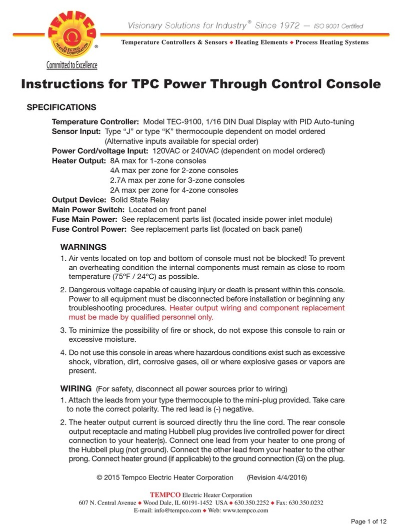
Tempco
Tempco TEC-9100 instructions
Mitsubishi Electric
Mitsubishi Electric MELSEC iQ-R Series user manual
Siemens
Siemens 91-HF Installation and service instruction
Control Techniques
Control Techniques unidrive sp Advanced user's guide
