6
Rear Axle Brakes - The vehicle’s rear axle brakes are
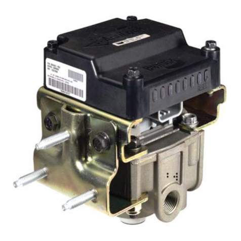
controlled by the MC-14™modulator controller (EC-14™
controllerandM-12™modulator).Likethe standard service
relayvalveitreplaces,theM-12™modulatordelivers brake
application pressure to the service chambers on the rear
axle equally. Two speed sensors on the rear axle “report”
changes in acceleration and deceleration to the EC-14™
controller. If required, the EC-14™controller adjusts the
applicationpressureto the rear axle servicebrakes,viathe
M-12™modulator,basedonthewheelbehavior“reported”
toitbythe speed sensors. In thecaseofvehiclesequipped
with tandem rear axles (6x2, 6x4), the speed sensors are
installed on the axle that is most likely to lose traction first.
TheMC-14™modulator controllercontrolsallservicebrakes
onthe tandemequally.
TheEC-14™controller utilizesa “SelectSmart”brakecontrol
philosophy for the rear axle brakes. This means that the
EC-14™controllerwillinitiallyadjust application pressure to
allrearaxleservicechambersbasedonthespeedinformation
from the first wheel to approach a locked condition. The
initialpressure adjustment willattempttoprevent allwheels
ontheaxle(s)fromlocking.Ifasubstantialbrakingdifference
is detected between the two wheels on the axle equipped
withthespeedsensors,theEC-14™controller will override
the first air pressure adjustment and allow one wheel to
lock. Both wheels including the locked wheel will continue
to be monitored for speed and braking difference changes
thatwouldrequirepressure adjustments.
Steering Axle Brakes - The steering axle brakes are
controlledby theEC-14™controllerand theM-21™orM-22™
modulator.Althoughconnectedtothe EC-14™controllervia
a wire harness, the M-21™or M-22™modulator is not an
integralpartof the MC-14™modulator controller assembly.
Brake application air passes through the M-21™or M-22™
modulator on its way to the front axle service chambers
fromthe footvalve.
Two speed sensors on the front axle “report” changes in
accelerationanddecelerationtothe EC-14™controller.
The EC-14™controller uses a “Select Low” brake control
philosophyfor thefrontaxle brakes.Itwill attempttoprevent
wheel lock by adjusting application pressure to both front
axleservice chambersbasedonthespeed informationfrom
thefirst wheeltoapproach alockedcondition. TheM-21™or
M-22™modulator provides the EC-14™controller with the
means of adjusting front axle service application pressure
whenrequired.
NON-ANTILOCK BRAKE APPLICATION
During normal braking, the brake valve simultaneously
deliversair tothecontrolport oftheM-12™modulator onthe
rear axle(s) as well as to and through the M-21™or M-22™
modulatoron the frontaxle.The M-12™modulatorfunctions
thesameasstandardservicerelayvalveandapplies air to
therearaxleservicebrakes.Becausethe M-21™or M-22™
modulator does not have a relay valve function, service air
passesthroughitto a quick release valveandfromthereto
thefrontaxleservicechambers.The servicebrakes arethus
applied.
Ifthespeed sensors donotdetectan impending wheellock
up, the EC-14™controller does not initiate any corrective
actionandthevehiclecomestoastopinanormalfashion.
ANTILOCK CONTROLLED BRAKE
APPLICATION - SYSTEM FULLY OPERATIONAL
Ifaservicebrakeapplicationis madeand thespeedsensors
detect an impending wheel lockup on an axle, the EC-14™
controller will immediately begin modification of the brake
application using the antilock modulator(s) at the affected
axle(s).
Solenoid valves contained in the modulator are energized
anddeenergizedbytheEC-14™controllerinordertomodify
thebrakeapplication.Whenasolenoidcoilis energized its
shuttlemoves,anddependinguponthefunctionofthespecific
solenoid, it either opens or closes, thereby causing the
exhaustorre-applicationofairpressuretothebrakechamber.
The solenoids in either the M-12™or M-21™modulator are
controlled independently by the EC-14™controller. By
opening and closing the solenoid valves in the appropriate
modulator,theEC-14™controller is actuallysimulatingwhat
thedriverdoeswhen he “pumps the brakes”.
It must be remembered however that unlike the driver, the
EC-14™controller is able to “pump” brakes on either the
frontorrearaxle(s),orboth,independentlyandwithfargreater
speedandaccuracy.
ANTILOCK SYSTEM OPERATION -
COMPONENT FAULT STRATEGY
The Bendix®EC-14™controller handles equipment faults
usingaconservativefail-safephilosophy.Anysingleelectrical
problem with a component devoted to antilock braking,
resultsinsimultaneous illuminationoftheantilock condition
lampon thedashand atroubleshootingLED ontheEC-14™
controller. Depending upon the type of problem and its
position of occurrence the EC-14™controller can continue
antilockfunctionat a lower performance level, disableallof
the antilock on the vehicle or only a portion. When antilock
is disabled, the brakes on the affected axle(s) revert to
standardairbraking.
Complete antilock system shut down will occur if:
•Electrical power is below or above the 10 to 17 volt
operatingrange.
•A controller fault is detected.
•Twoormorefaults,regardless of where, are detected.
