Lincoln Electric MAXsa 10 User manual

IM2062
06/2017
REV01
MAXsa™ 10 CONTROLLER
OPERATOR’S MANUAL
ENGLISH
THE LINCOLN ELECTRIC COMPANY
22801 St. Clair Ave., Cleveland Ohio 44117-1199 USA
www.lincolnelectric.eu

English English
I
THE LINCOLN ELECTRIC COMPANY
EC DECLARATION OF CONFORMITY
Manufacturer and technical documentation
holder:
The Lincoln Electric Company
Address:
22801 St. Clair Ave.
Cleveland Ohio 44117-1199 USA
EC Company:
Lincoln Electric Europe S.L.
Address:
c/o Balmes, 89 - 802a
08008 Barcelona
SPAIN
Hereby declare that equipment:
K2803, Power Wave AC/DC 1000 SD
K2444, CE Filter
K2814, MAXsa 10 Controller
K2626, MAXsa 19 Controller
K2370, MAXsa 22 Feed Head
K2312, MAXsa 29 Feed Head
(Sales codes may contain suffixes and prefixes.)
Is in conformity with Council Directives
and amendments:
Electromagnetic Compatibility (EMC) Directive 2014/30/EU
Low Voltage Directive (LVD) 2014/35/EU
Standards: EN 60974-1: 2012, Arc Welding Equipment – Part 1: Welding Power
Sources;
EN 60974-5: 2013, Arc Welding Equipment-Part 5: Wire Feeders;
EN 60974-10: 2014, Arc Welding Equipment-Part 10: Electromagnetic
compatibility (EMC) requirements;
CE marking affixed in 09
SamirFarah,ManufacturerDarioGatti,EuropeanCommunityRepresentative
ComplianceEngineeringManagerEuropeanEngineeringManager
19January2017
MCD240f
20January2017

English English
II
12/05
THANKS! For having chosen the QUALITY of the Lincoln Electric products.
Please Examine Package and Equipment for Damage. Claims for material damaged in shipment must be notified
immediately to the dealer.
For future reference record in the table below your equipment identification information. Model Name, Code &
Serial Number can be found on the machine rating plate.
Model Name:
………………...…………………………….…………………………………………………………………………………………..
Code & Serial number:
………………….……………………………………………….. …………………………………………………….……………..
Date & Where Purchased:
…………………………………………………………………... ……………………….…………………………………………..
ENGLISH INDEX
Technical Specifications...................................................................................................................................................... 1
Electromagnetic Compatibility (EMC) ................................................................................................................................. 2
Safety .................................................................................................................................................................................. 3
Installation Instructions........................................................................................................................................................ 4
Operation Instruction ......................................................................................................................................................... 12
WEEE ................................................................................................................................................................................ 25
Spare Parts ....................................................................................................................................................................... 25
Authorized Service Shops Location.................................................................................................................................. 25
Electrical Schematic.......................................................................................................................................................... 26
Suggested Accessories..................................................................................................................................................... 27

English English
1
Technical Specifications
MAXsa™ 10 CONTROLLER
INPUT VOLTAGE AND CURRENT
MODEL
V
OLTAGE* INPUT AMPS*
K2814-3 40VDC 1.0
PHYSICAL DIMENSIONS
HEIGHT (mm) WIDTH (mm) DEPTH (mm) WEIGHT (kg)
381 259 102 11,3
TEMPERATURE RANGES
OPERATING TEMPERATURE RANGE (ºC) STORAGE TEMPERATURE RANGE (ºC)
-10 to +40 -40 to +85
IP23 Insulation Class
*When not driving a motor

English English
2
Electromagnetic Compatibility (EMC)
11/04
This machine has been designed in accordance with all relevant directives and standards. However, it may still generate
electromagnetic disturbances that can affect other systems like telecommunications (telephone, radio, and television) or
other safety systems. These disturbances can cause safety problems in the affected systems. Read and understand
this section to eliminate or reduce the amount of electromagnetic disturbance generated by this machine.
This machine has been designed to operate in an industrial area. To operate in a domestic area it is
necessary to observe particular precautions to eliminate possible electromagnetic disturbances. The
operator must install and operate this equipment as described in this manual. If any electromagnetic
disturbances are detected the operator must put in place corrective actions to eliminate these disturbances
with, if necessary, assistance from Lincoln Electric.
Before installing the machine, the operator must check the work area for any devices that may malfunction because of
electromagnetic disturbances. Consider the following.
Input and output cables, control cables, and telephone cables that are in or adjacent to the work area and the
machine.
Radio and/or television transmitters and receivers. Computers or computer controlled equipment.
Safety and control equipment for industrial processes. Equipment for calibration and measurement.
Personal medical devices like pacemakers and hearing aids.
Check the electromagnetic immunity for equipment operating in or near the work area. The operator must be sure
that all equipment in the area is compatible. This may require additional protection measures.
The dimensions of the work area to consider will depend on the construction of the area and other activities that are
taking place.
Consider the following guidelines to reduce electromagnetic emissions from the machine.
Connect the machine to the input supply according to this manual. If disturbances occur if may be necessary to take
additional precautions such as filtering the input supply.
The output cables should be kept as short as possible and should be positioned together. If possible connect the
work piece to ground in order to reduce the electromagnetic emissions. The operator must check that connecting
the work piece to ground does not cause problems or unsafe operating conditions for personnel and equipment.
Shielding of cables in the work area can reduce electromagnetic emissions. This may be necessary for special
applications.
WARNING
EMC classification of this product is class A in accordance with electromagnetic compatibility standard EN 60974-10 and
therefore the product is designed to be used in an industrial environment only.
WARNING
The Class A equipment is not intended for use in residential locations where the electrical power is provided by the public
low-voltage supply system. There can be potential difficulties in ensuring electromagnetic compatibility in those locations,
due to conducted as well as radio-frequency disturbances.

English English
3
Safety
11/04
WARNING
This equipment must be used by qualified personnel. Be sure that all installation, operation, maintenance and repair
procedures are performed only by qualified person. Read and understand this manual before operating this equipment.
Failure to follow the instructions in this manual could cause serious personal injury, loss of life, or damage to this
equipment. Read and understand the following explanations of the warning symbols. Lincoln Electric is not responsible
for damages caused by improper installation, improper care or abnormal operation.
WARNING: This symbol indicates that instructions must be followed to avoid serious personal injury,
loss of life, or damage to this equipment. Protect yourself and others from possible serious injury or
death.
READ AND UNDERSTAND INSTRUCTIONS: Read and understand this manual before operating
this equipment. Arc welding can be hazardous. Failure to follow the instructions in this manual could
cause serious personal injury, loss of life, or damage to this equipment.
ELECTRIC SHOCK CAN KILL: Welding equipment generates high voltages. Do not touch the
electrode, work clamp, or connected work pieces when this equipment is on. Insulate yourself from
the electrode, work clamp, and connected work pieces.
ELECTRICALLY POWERED EQUIPMENT: Turn off input power using the disconnect switch at the
fuse box before working on this equipment. Ground this equipment in accordance with local electrical
regulations.
ELECTRICALLY POWERED EQUIPMENT: Regularly inspect the input, electrode, and work clamp
cables. If any insulation damage exists replace the cable immediately. Do not place the electrode
holder directly on the welding table or any other surface in contact with the work clamp to avoid the
risk of accidental arc ignition.
ELECTRIC AND MAGNETIC FIELDS MAY BE DANGEROUS: Electric current flowing through any
conductor creates electric and magnetic fields (EMF). EMF fields may interfere with some
pacemakers, and welders having a pacemaker shall consult their physician before operating this
equipment.
CE COMPLIANCE: This equipment complies with the European Community Directives.
FUMES AND GASES CAN BE DANGEROUS: Welding may produce fumes and gases hazardous to
health. Avoid breathing these fumes and gases. To avoid these dangers the operator must use
enough ventilation or exhaust to keep fumes and gases away from the breathing zone.
ARC RAYS CAN BURN: Use a shield with the proper filter and cover plates to protect your eyes from
sparks and the rays of the arc when welding or observing. Use suitable clothing made from durable
flame-resistant material to protect you skin and that of your helpers. Protect other nearby personnel
with suitable, non-flammable screening and warn them not to watch the arc nor expose themselves to
the arc.
WELDING SPARKS CAN CAUSE FIRE OR EXPLOSION: Remove fire hazards from the welding
area and have a fire extinguisher readily available. Welding sparks and hot materials from the welding
process can easily go through small cracks and openings to adjacent areas. Do not weld on any
tanks, drums, containers, or material until the proper steps have been taken to insure that no
flammable or toxic vapors will be present. Never operate this equipment when flammable gases,
vapors or liquid combustibles are present.
WELDED MATERIALS CAN BURN: Welding generates a large amount of heat. Hot surfaces and
materials in work area can cause serious burns. Use gloves and pliers when touching or moving
materials in the work area.
SAFETY MARK: This equipment is suitable for supplying power for welding operations carried out in
an environment with increased hazard of electric shock.

English English
4
CYLINDER MAY EXPLODE IF DAMAGED: Use only compressed gas cylinders containing the
correct shielding gas for the process used and properly operating regulators designed for the gas and
pressure used. Always keep cylinders in an upright position securely chained to a fixed support. Do
not move or transport gas cylinders with the protection cap removed. Do not allow the electrode,
electrode holder, work clamp or any other electrically live part to touch a gas cylinder. Gas cylinders
must be located away from areas where they may be subjected to physical damage or the welding
process including sparks and heat sources.
MOVING PARTS ARE DANGEROUS: There are moving mechanical parts in this machine, which
can cause serious injury. Keep your hands, body and clothing away from those parts during machine
starting, operating and servicing.
Installation Instructions
Read this entire section before installation or operation
of the machine.
General Physical Description
The MAXsa™ 10 CONTROLLER is a user interface
and a feeder controller. The control is used to set all
welding parameters and control any travel
mechanisms. High-speed digital cables connect the
control, wire drive, and the Power Wave power
source together.
The MAXsa™ 10 CONTROLLER is a self-contained
control box designed to control the entire weld arc at
one location.
The user interface utilizes alphanumeric displays for
advanced text messaging providing the end user
with an intuitive inter- face allowing for easy set up
and real-time control of all weld- ing parameters.
An eight button memory section has been included
which pro- vides easy storage and recall of stored
welding parameters.
The user interface can be removed from the control
box and connected as a Pendant for remote control
near the arc.
General Functional Description
The MAXsa™ 10 CONTROLLER is one of the most
versatile user interfaces ever created. Easy to use
features make it a snap to adjust the arc for specific
preferences.
The user interface brightly displays essential
welding informa- tion. Use it to quickly adjust weld
settings, arc starting para- meters, arc end
parameters and set-up information.
The memories allow for up to eight weld schedules
to be stored and quickly recalled. The user interface
allows for mul- tiple levels of limits and lockouts.
Digital communications to the power source provide
the most accurate and reliable operation possible.
When the MAXsa™ 10 CONTROLLER is coupled to
the Power Wave® AC/DC 1000 SD welding power
source, the result is a welding system with the best
arc performance on the market.
Definitions of Welding Modes
NON-SYNERGIC WELDING MODES
A Non-synergic welding mode requires all welding
process variables to be set by the operator.
SYNERGIC WELDING MODES
A Synergic welding mode offers the simplicity of
single knob control. The machine will select the
correct voltage and amperage based on the wire
feed speed (WFS) set by the oper ator.
See the Power Wave® AC/DC 1000 SD Operator’s
Manual for available weld modes.
COMMON WELDING ABBREVIATIONS
SAW
Submerged Arc Welding
GRAPHIC SYMBOLS THAT APPEAR ON THIS
MACHINE OR IN THIS MANUAL
PENDENT ARCLINK
CONNECTOR
WIRE FEEDER
CONTROLLER ARCLINK
INPUT CONNECTOR
FLUX HOPPER
CONNECTOR
TRAVEL CARRIAGE
CONNECTOR
Design Features
Easy control of all weld parameters.
8 Memories for easy storage and recall of weld
schedules.
Weld parameter limit setting and lockout
capabilities.

English English
5
Digital communications for accurate and reliable
performance.
PC boards are potted in epoxy for the ultimate in
outdoor protec- tion.
Connectors are filled with environmental protective
grease.
Designed for the Power Wave®AC/DC 1000 SD
series of prod- ucts for the best arc in the industry.
Wire feed speed accuracy calibrated to within 2%.
Digital display of voltage and wire feed speed.
Tachometer controlled wire drive motor.
Flux Fill Switch.
Bright, high intensity digital read-outs.
Option to convert to hand-held pendant included.
Recommended Processes and
Equipment
The MAXsa™ 10 CONTROLLER is best suited for
submerged arc welding only with the Power Wave®
AC/DC 1000 SD, the MAXsa™ 22 or the MAXsa™
29 Feed Heads.
SAW
Welding Voltage
Wire feed parts are electrically live while welding and
while inching wire (with Touch Sense feature selection).
The electrically live parts are listed below:
Electrode Electrode Reel
Wire Drive Motor Drive Rolls
Gear Box Cross-seam Adjuster
Wire Straightener Welding Nozzle
Welding Cables Welding Cable Terminal
WARNING
Do not touch electrically live parts or electrodes with
your skin or wet clothing.
Insulate yourself from the work and ground.
Always wear dry insulating gloves.
MECHANICAL HAZARDS
Welding fixture or wire feeder will move during
welding or inching. Keep away from pinch points.
Electrode reel and drive rolls turn during welding or
inching. Keep gloved hands away from areas that
may catch the glove
Location and Mounting
The MAXsa™ 10 Controller will operate in harsh
environments and can be used outdoors with an IP 23
rating. Even so, it is important that simple preventative
measures are followed in order to assure long life and
reliable operation. The MAXsa™ 10 Controller must be
located where there is little risk of impacts to the
Controller.
This equipment is for industrial use only and it is not
intended for use in residential locations where the
electrical power is provided by the pub- lic low-voltage
supply system. There can be potential difficulties in resi-
dential locations due to conducted as well as radiated
radio-frequency disturbances. The EMC or RF
classification of this equipment is Class A.
High Frequency Protection
Locate the MAXsa™ 10 Controller away from radio
controlled machinery. The normal operation of the
MAXsa 10 Controller may adversely affect the operation
of RF controlled equipment, which may result in bodily
injury or damage to the equipment.
Auxiliary Equipment Input Power
Connection
The MAXsa 10 Controller has the ability to control
auxiliary equipment such as feeders, flux hoppers and
travel motors using solid state relays. There are three
relays (CR1,CR2 &CR3) in the MAXsa 10 Controller,
controlled by two independent coil drivers. The coils of
CR1 and CR2 are in parallel, therefore, they must turn
ON and OFF at the same time. The CR1 and CR2 relays
are designated for driving travel motors to control
motion. CR3 is driven separately, and is designated to
control flux hopper operation.
MAXsa 10 Controller Relay Ratings:
Coil: 12Vdc, resistance = 86 ohms at 25° C
Normally Closed (N.C.) Contacts: 3A @ 277VAC
Normally Open (N.O.) Contacts: 30A @ 277VAC
The MAXsa 10 Controller does not provide the input
power to feed any equipment, other than the MAXsa 22
or the MAXsa 29 feeders. Therefore a separate power
feed must be provided by the end user. The MAXsa 10
Controller has been shipped standard with all of the
wiring and connectivity to operate the Lincoln K325 TC-3
Travel Carriage (4-pin cable connector) and the Lincoln
K219 Automatic Flux Hopper (3-pin cable connector).
The CR2 Relay is wired to the 4-pin travel connector,
and the CR3 Relay is wired to the 3-pin flux connector,
both located on the bottom of the MAXsa 10 Controller.
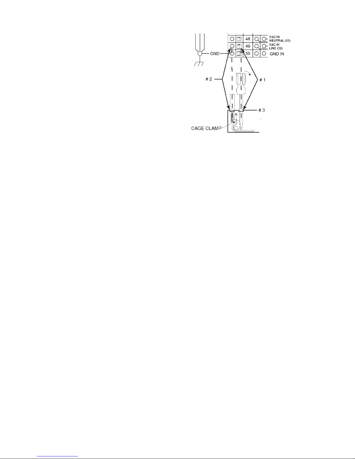
If either of these is to be used with the MAXsa 10
Controller, the end-user must provide the 115VAC input
power to the terminal strip located inside the MAXsa 10
Controller. Access to the terminal strip may be obtained
via one of the two .875” dia. (22.2mm) access holes in
the bottom of the MAXsa 10 Controller. These access
holes are shipped with plug buttons installed. Remove
the plug button and install a suitable strain relief to
protect the wires. See Figure #1
WARNING
Although input power to MAXsa 10 Controller is turned
off, the customer installed auxiliary input may be
energized! Ensure that all input power to the MAXsa 10
Controller is turned off before opening the cover.
1. STATUS LIGHT
2. PENDANT CONNECTOR
3. MAXsa™ 22 or 29 WIRE DRIVE CONNECTOR
(14-PIN)
4. POWER WAVE®AC/DC 1000 ARCLINK
CONNECTOR
5. FLUX HOPPER CONNECTOR
6. TC-3 TRAVEL CARRIAGE CONNECTOR
7. ACCESS HOLE
Figure #1: MAXsa 10 Connections

English English
6
Interfacing to the MAXsa™ 10
Controller
The MAXsa 10 Controller is a versatile controller. The
User Interface can be removed and used as a hand-held
pendant. Most circuits can be accessed through the
screw less terminal strip. The auxiliary relays can control
standard Lincoln equipment, or they can be used to
control any other auxiliary equipment custom controls.
PLC interfacing to control starting, stopping, motion, etc,
can be accomplished with ease.
Using the Controller as a Hand-held Pendant:
1. Remove the 4 screws from the MAXsa 10 Controller
that hold the cover. See Figure #2.
2. Remove the 2 screws that hold the pendant in the
brackets. Use the access holes shown.
3. Extend the control cable as needed with an Arc Link
cable. See Figure #2.
A. Front View Cover
B. Cover Screws (4 Places)
C. Cover
D. Pendant Screws (2 Places)
E. Access Hole
F. K1543-XX or K2683-xx Arclink Cable (Optional)
Figure #2: Hand Held Pendant

English English
7
Auxiliary Input Power Connection
Instructions
Use the appropriate size leads, at least 14AWG – 2wire
with ground
1. Remove two Phillips Head screws on right side of
front panel of hinged door to access terminal strip.
2. Remove a plug button and install a box connector to
provide strain relief for the input power leads.
3. Strip off 1/4”(6.4mm) of insulation from the leads
and route them through the strain relief.
4. Locate the 4-terminal blocks, numbered #48, #49,
and #50. These are to be used to bring in auxiliary
power. Terminal block #50 is used for the input
ground connection. This termi- nal block is color-
coded green and yellow for easy identifica- tion.
Terminal blocks #48 and #49 are to be used to
connect the input power circuit. (See Figure #3).
5. Using a flat-head screwdriver with a blade
dimension of 0.137"(3.5mm) x 0.020"(.51mm), insert
the screwdriver into the square hole next to the
mounting hole to be used on the ter- minal strip. The
screwdriver should be inserted until it bottoms out.
This opens the screwless cage clamping style wire
inser- tion port. With the cage clamp opened insert
the wire into the round port until it bottoms out.
While holding the lead securely, remove the
screwdriver from the terminal block. This closes the
cage clamp onto the lead holding it securely. Any
open port on blocks #48, #49, and #50 may be
used.
Terminal blocks 48 and 49 are shipped connected to the
contacts of CR2 and CR3 by leads 531 and 532. These
relay contacts are also connected to the 4-pin Travel
connector and the 3-pin Flux connector located on the
bottom of the MAXsa™ 10 Controller. CR1 is available
for a separate customer connection, but it will turn ON
and OFF with CR2. Therefore, if Lincoln auxiliary
equipment is to be used, connecting 115VAC to the
terminal strip is all that is required to power the devices.
NOTE: The contacts of CR1 are not connected to
terminals #48 and #49 when shipped. Applying power
the #48 and #49 terminals will not transfer voltage to the
CR1 relay. Connect leads from the #48 terminal to the
#4 terminal and from the #49 terminal to the #3 terminal
to supply power to the common contacts of the relay.
Once input power is applied to the terminal strip, this
voltage is always on terminal strip blocks #3, #4 (if
connected), #11, #17, and #18. These are the inputs to
the solid state relay contacts. Input voltage is also
present on terminal strip blocks #7, #8 (if connected),
#15, #21, and #22 due to the N.C. contacts on the
relays. When the CR1 relay is energized, input power is
transferred to terminal strip blocks #5 and #6 (if
connected). When the CR2 relay is energized, input
power is transferred to terminal strip block #13. When
the CR3 relay is energized, input power is transferred to
terminal strip blocks #19 and #20. CR1 and CR2 will be
turned ON and OFF at the same time.
#1: INSERT SCREW DRIVER HERE
#2: INSERT WIRE HERE
#3: REMOVE SCREW DRIVER FROM CAGE CLAMP
HOLE.
Figure #3: Auxiliary Connections

English English
8
Controlling Non-Lincoln auxiliary
Equipment
Figure #4: Controlling Non-Lincoln Equipment
Custom motion control and/or other auxiliary equipment
can be powered using the terminal strip and relays. To
use non-Lincoln motion control and/or flux hoppers,
follow instructions below. See Figure #4.
1. Remove all input power to the MAXsa™ 10
Controller including any auxiliary power supplies.
2. Remove the wire duct cover to gain access to the
leads on the right side of the terminal strip.
3. Remove a plug button from one of the .875”
(22.2mm) access holes on the bottom of the MAXsa
10 Controller control box. Install a suitable strain
relief to protect the leads. See Figure #1.
4. Remove the leads going from the terminal strip to
the corresponding connectors, i.e. terminal strip
blocks #11, #13, and #16 for the 4-pin TC-3 Travel
Carriage or terminal strip blocks #19, #20, and #23
for the 3-pin Automatic Flux Hopper. See the Wiring
Diagram.
5. These loose leads can be taped and secured in the
wire duct.
6. Any custom or non-Lincoln equipment can be
powered by the normally open contacts from relays
CR1, CR2, or CR3. The contacts for CR1 are
connected to the terminal strip blocks #3 through
#8. The contacts for CR2 are Connected to terminal
strip blocks #10 through #15. The contacts for CR3
are connected to terminal strip blocks #17 through
#22. See Figure #3.
CR1 and CR2 relay coils are in parallel and are BOTH
turned ON and OFF as determined by the Travel
Options setting (P12 in the Setup Menu) as long as the
TRAVEL MODE is set to AUTO. CR3 turns ON with the
START command and OFF with the STOP Command.
7. The supply voltage to power the devices is provided
by the end user. As shipped, the MAXsa™ 10 has
the auxiliary supply blocks (terminal strip blocks #48
and #49) connected to the CR2 relay and CR3 relay
inputs, respectively. When the end user connects a
supply to the AUX blocks #48 and #49, this voltage
will be jumpered to the CR2 and CR3 relay inputs
on terminal strip blocks #11, #17, and #18.
NOTE: The CR1 relay is not connected to the AUX
terminal strip blocks; the customer must connect power
to this relay if it is to be used. See relay ratings listed
earlier.
8. Connect input supply voltage per the Auxiliary Input
Power Connection Instructions listed earlier.
9. The relays can also be used to provide contact
closure for any interfacing signals out using the
normally open contacts. An external auxiliary supply
voltage would not be necessary to use the relays as
hard contact closure out signals.
NOTE: The CR1 relay as shipped does not have AUX
leads connected to it. This relay operates as described
above and has two normally open / normally closed
contacts that could be used as a signal out when
interfacing to PLC’s or custom controls.
Shutdowns Input
The MAXsa™ 10 Controller has two shutdown inputs
available on the terminal strip. These are independent,
normally closed inputs that can be used for limit
switches, PLC inputs, etc, in order to shut down the
welding operation for any reason. Shutdown #1 is
located on terminal strip blocks #24 and #25. Shutdown
#2 is located on terminal strip blocks #26 and #27.
1. Remove all input power to the MAXsa™ 10
Controller including any auxiliary power supplies.
2. Remove the wire duct cover to gain access to the
leads on the right side of the terminal strip.
3. Remove one of the plug buttons located on the
bottom of the MAXsa 10 Controller control box and

English English
9
install some type of strain relief for the auxiliary
control leads.
4. Connect the external shutdown circuit to either of
the shutdown terminal blocks, #24 & #25, and/or
#26 & #27. A normally closed circuit must be
connected – the MAXsa 10 Controller will recognize
an open circuit as a shutdown command.
5. Remove the shorting jumpers imbedded in the
center of the terminal strip with a small screwdriver
for the shutdown circuits to be used.
When a shutdown input is received, all welding will stop
and an error message will be displayed on the MAXsa
10 Controller. The shutdown circuit must be closed
before resetting Controller. To reset the system, the
Mode Select Panel display will prompt the user to press
the left Mode Select Panel Pushbutton.
1. Shorting Jumper
2. Connect STOP Input Here
Figure #5: Shutdown and Stop Inputs
Stop Input
The MAXsa™ 10 Controller has a Stop Input available
on the terminal strip. The Stop Input will work just like
pressing the STOP Pushbutton. This circuit is in parallel
with the STOP Pushbutton located on the Switch Panel.
Unlike the Shutdown Inputs, which completely shutdown
all welding and auxiliary equipment, the STOP Input will
allow all welding and auxiliary motion to continue based
on the END OPTIONS configurations in the MAXsa™ 10
Controller. See Figure #5.
1. Remove all input power to the MAXsa 10 Controller
including any auxiliary power supplies.
2. Remove the wire duct cover to gain access to the
leads on the right side of the terminal strip.
3. Remove one of the plug buttons located on the
bottom of the MAXsa™ 10 Controller control box
and install some type of strain relief for the auxiliary
control leads.
4. Connect the external Stop Input circuit to terminal
blocks #39 and #41
NOTE: The STOP circuit only needs a momentary
closure to be recognized by the MAXsa™ 10 Controller

English English
10
Connection Diagram: Single Arc System
Figure #6
Connection Diagrams for Additional
Configurations (Multi- Arc and Parelleled Power Sources)
are in the Power Wave AC/DC 1000SD Operators Manual

English English
11
Installation Instructions for MAXsa™10 Being used with Power Wave®AC/DC SD
WARNING
ELECTRI SHOCK Can kill.
Turn the supply power OFF at the disconnect switch before working on this equipment.
Do not touch electrically hot parts.
Only qualified personnel should install, use or service this equipment.
Follow all national and local safety procedures.
Wear the appropriate Personal Protective Equipment
Note: DO NOT DISTURB ANY OTHER HARNESS, LEAD, OR EXISTING GROUND CONNECTIONS DURING
INSTALLATION.
1. Open control box and locate S27981-[ ] (L11087-[ ]) and G4018-[ ] boards.
2. Remove J86 connector from the S27981-[ ] (L11087-[ ]) board.
3. Remove J331 from the G4018-[ ] board.
4. 4- G4018-[ ] is no longer needed. It can stay or be removed.
5. Replace S27981-[ ] (L11087-[ ]) board with the S30221-[ ] (G6752-[ ]) board.
6. 6- Reconnect the J331 connector to J88 on the S30221-[ ] (G6752-[ ]) board, then reconnect the rest of the
connectors.
7. Reconnect the input power and assure proper output.

English English
12
Operation Instruction
1. STATUS LIGHT
2. PENDANT CONNECTOR
3. MAXsa™ 22 or 29 WIRE DRIVE CONNECTOR (14-PIN)
4. POWER WAVE®AC/DC 1000 ARCLINK CONNECTOR
5. FLUX HOPPER CONNECTOR
6. TC-3 TRAVEL CARRIAGE CONNECTOR
7. ACCESS HOLE
Figure #7: Input & Output Connections
1. MODEL SELECT PANEL (MSP) DISPLAY
2. VOLTS CONTROL
3. VOLTS DISPLAY
4. VOLTS INDICATOR
5. START BUTTON
6. WELD OUTPUT INDICATOR
7. STOP BUTTON
8. SET UP MENU INDICATOR
9. ARC START/END OPTIONS SELECTOR
10. START OPTIONS INDICATOR
11. END OPTIONS INDICATOR
12. FEED REVERSE
13. FEED FORWARD
14. WELD MODE, OPTIONS, AND LIMITS CONTROL
15. MEMORY BUTTONS (8)
16. FREQUENCY AND BALANCE INDICATOR
17. WELD MODE INDICATOR
18. WELD MODE SELECTOR
19. FLUX FILL SWITCH
20. TRAVEL SWITCH (AUTO/OFF/MANUAL)
21. AMPS INDICATOR
22. WFS INDICATOR
23. AMPS/WFS DISPLAY
24. AMPS/WFS CONTROL

English English
13
Power-up Sequence
When power is first applied to the machine the MODE
SELECT Display reads “MAXsa Initializing...”. Once the
PowerWave AC/DC has intialized (20 to 60 seconds) a
“lamp test” is performed.
All discrete LED’s, seven segment displays and
alpha numeric displays will be turned ON turned ON
for 2 seconds
After 2 seconds all displays are turned OFF again
and the MODE SELECT Display will show:
After initialization is complete,the MSP Display will show
the weld mode, the upper displays will show the
parameters that were selected when the machine was
last powered down and the WELD MODE Indicator will
be ON.
Wire Feeder Setup
Use the INCH DOWN pushbutton to insert wire into the
feed mechanism.
WARNING
Prior to inserting the wire make sure that the “Touch
Sense” option is disabled. (P.15 in the Setup Menu).
Setting Feed Forward/Reverse
While pressing either the FEED FORWARD or FEED
REVERSE pushbutton the MSP Display will read as
shown in Figure above and the preset wire feed speed
will be displayed on the left (AMPS/WFS) display.
The feed speed can be changed by adjusting the control
knob below the display while pressing either button.
FEED REVERSE Use to retract the wire from
the feed mechanism.
FEED FORWARD Feeds the wire downward
torward the work piece.
NOTE: The MAXsa™ 10 has an option in the Setup
Menu (P.15) to enable the “Touch Sense” circuitry. See
the Setup Menu. When P.15 is enabled and the FEED
FORWARD button is pressed, the display will read.
NEW PICTURE!!!!
WARNING
This “Hot Feed” feature enables the output of the power
source and there is voltage on the wire while inching
down. Avoid touching any exposed parts as defined in
the SAFETY PRECAUTIONS.
Changing and Setting weld Modes
To select a weld mode, press the WELD MODE
SELECTOR button until the WELD MODE indicator
comes ON (it may already be lit by default at power up).
Turn the control; knob to select the desired mode. After
about 1 second, the parameters for the new mode will be

English English
14
displayed. These parameters can be adjusted with the
control knobs below each display.
NOTE: CC Modes will show AMPS in the upper left
display. CV Modes will show wire feed speed and the
WFS indicator will be lit.
Frequency/Balance Control
FREQUENCY ADJUST
Press the WELD MODE selector until the
FREQUENCY/BALANCE indicator comes ON and the
MSP Display reads “Frequency”. If the selected mode
allows for frequency adjustment, the Control Knob can
be used to select the desired frequency between 20 and
100hz.
Use Frequency to fin a tune stability of imbalanced
waveforms and multiple arc systems
Frequency adjustment can be used to fine tune
stability of imbalanced waveforms and multiple arc
system.
BALANCE ADJUST
Press the WELD MODE selector until the MSP Display
reads “Balance”. If the selected mode allows for balance
adjustment, the Control Knob can be used to select the
desired wave balance through a range of 25% to 75%.
NEW PICTURE!!!!
Adjusting the Balance (the ratio between Positive and
Negative half cycle ‘on time’) changes the deposition for
more efficient welding.
OFFSET ADJUST
Press the WELD MODE selector until the MSP Display
reads “Offset”. If the selected mode allows for offset
adjustment, the Control Knob can be used to select the
desired offset. The amount of offset allowed is
determined by the selected weld mode.
Independent control of the Positive and Negative cycles
allows for more precise control of penetration and
deposition.
Weld Mode Searching
The Weld Mode Search feature allows the selection of a
welding mode based on certain criteria (wire size,
process type, etc.).

English English
15
SEARCHING FOR A WELD MODE
To search for a mode, press and release the control
knob while the WELD MODE indicator is lit. Another
way to search for a mode is to turn the control knob until
“Weld Mode Search” is displayed. This will appear in
between the highest and the lowest weld mode number.
Once “Weld Mode Search” is displayed, pressing the
right push- button labeled “Begin” will start the search
process.
During the search process, pressing the right pushbutton
typically acts as a “next” button and the left pushbutton
typically acts as a “back” button. Pressing the control
knob also acts as a “next” button.
Rotate the control knob then press to select relevant
welding details such as welding process, wire type, wire
size, etc.
When the final selection is made, the MAXsa™ 10 will
automati- cally change to the weld mode found by the
Weld Mode Search process.
Earlier products may not have this feature. To activate
this fea- ture, a software update may be needed from
www.power- wavesoftware.com
Multiple Arc Configuration
Power Wave®AC/DC 1000SD / MAXsa™ systems can
be used in multiple arc set ups with up to six arcs. To
minimize magnetic interaction between the arcs it is
imperative that they be phased correctly. Phasing is
essentially a time offset between the waveforms of
different arcs. The phase of each arc is set via the User
Interface of the lead arc.
The ideal situation is to have adjacent arcs 90° offset as
illustrated in table below.
TABLE B.1 - PHASE RELATIONSHIP
In table B.1 when using 50% balance on all arcs
ARC 1 ARC 2 ARC 3 ARC 4 ARC 5 ARC 6
2 Arc
System 0° 90° XXXX
3 Arc
System 0° 90° 180° XXX
4 Arc
System 0° 90° 180° 270° XX
5 Arc
System 0° 90° 180° 270° 0° X
6 Arc
System 0° 90° 180° 270° 0° 90°
(for balances waveforms only)
See the Power Wave®AC/DC Operator’s Manual for
more information regarding the configuration of multiple
arc systems.
Weld Sequence
The weld sequence defines the weld procedure from
beginning to end. All adjustments are made through the
user interface.
Start Options
The strike, start and upslope parameters are used at the
beginning of the weld sequence to establish a stable arc
and provide a smooth transition to the welding
parameters. They are described in the following:
ARC DELAY inhibits the wire feed for up to 5
seconds to provide an accurate weld start point.
Typically used in multi-arc systems.
STRIKE settings are valid from the beginning of the
sequence (Start) until the arc is established. They
control run-in (speed at which the wire approaches
the workpiece) and provide the power to establish
the arc. Typically output levels are increased, and
WFS is reduced during the strike portion of the weld
sequence.
START values allow the arc to become stabilized
once it is established. Extended start times or
improperly set parameters can result in poor
starting.
UPSLOPE TIME determines the amount of time it
takes to ramp from the start parameters to the weld
parameters. The transition is linear and may be up
or down depending on the relationship between the
start and weld settings.
Start Options Operation
Pressing the Arc Start/End Options Pushbutton will
illuminate the START OPTIONS LED and the Arc Delay
Time parameter will show on the MSP Display.
AGGIUNGERE FORO NUOVA!!!
Use the Mode Select Panel Control to select the
desired delay time. Press the Weld Mode Selector to
exit the Start parameters.
Repeated pressing of the Arc Start/End Options
pushbutton will scroll through the parameters. Turning
the Mode Select Panel Control, while on a parameter
will change its value.
When the Start Option is set to a value other than OFF,
the START OPTIONS LED will blink synchronous with
the WFS or Amps and/or the Volts LED located on the
Dual Display Panel prompting the user to enter these
parameters. The parameters that can be set by the user
in the START OPTIONS will be as follows:
ARC DELAY TIME
STRIKE WFS
STRIKE TIME

English English
16
START WFS/AMPS
START VOLTS
START TIME
UPSLOPE TIME
End Options
The downslope, crater, and burnback parameters are
used to define the end of the weld sequence. They are
defined in the following:
Downslope determines the amount of time it takes
to ramp from the weld parameters to the crater
parameters. The transition is linear and may be up
or down depending on the relationship between the
weld and crater settings.
Crater parameters are typically used to fill the crater
at the end of the weld and include both time and
output settings.
Burnback defines the amount of time the output
remains on after the wire has stopped. This feature
is used to prevent the wire from sticking in the weld
puddle and to condition the end of the wire for the
next weld. A burnback time of 0.4 second is
sufficient in most applications. The output level for
burnback is generally set to the same level as the
last active weld sequence state (either weld or
crater).
Restrike time determines how long the system will
try to re- establish the arc in the event of a poor start
or if the arc goes out for any reason (short circuit or
open circuit). During restrike, the WFS and outputs
are driven in an attempt to reestablish the arc.
oA restrike time of 1 to 2 seconds is
sufficient in most applications.
oA restrike time of 0 seconds allows the
restrike func- tion to continue indefinitely.
End Options Operation
Pressing the Arc Start/End Options Pushbutton after
scrolling through the Start Options will illuminate the
END OPTIONS LED and the Downslope Time
parameter will show on the MSP Display.
AGGIUNGERE NUOVA FOTO!!!!
Use the Mode Select Panel Control to select the
desired delay time. Press the Weld Mode Selector to
exit the End parameters.
Repeated pressing of the Arc Start/End Options
Pushbutton will toggle through the parameters. Turning
the Mode Select Panel Knob while on a parameter will
change its value. When the Crater Time is set to a value
other than OFF, the END OPTIONS LED will blink
synchronous with the WFS or Amps LED (depending on
CC or CV Weld Modes) and with the Volts LED located
on the Dual Display Panel prompting the user to enter
these parameters. The parameters that can be set by
the user in the END OPTIONS will be as follows:
DOWNSLOPE TIME
CRATER WFS/AMPS
CRATER VOLTS
CRATER TIME
BURNBACK TIME
RESTRIKE TIME
Setup Menu Features
The Setup Menu provides access for configuring user
preferences, which are generally only set at installation.
The user preferences are grouped as shown in the
following table.
PARAMETER DEFINITION
P.1 through P.99 Unsecured Parameters
(always adjustable)
P.101 through P.199 Diagnostic Parameters
(always read only)
P.501 through P.599 Secured Parameters (only
accessible with Weld
Manager)

English English
17
Accessing the Setup Menu
1. Mode Select Panel (MSP)
2. Setup Menu Indicator
3. Right Button
4. Control Knob
5. Left Button
1. ACCESS
To access the Setup Menu, Press the Left Button and
Right Button simultaneously. The Setup Menu Indicator
will light and the lower display will read as shown below.
Note: The Setup Menu cannot be accessed during
welding, or if a fault is displayed. To resume welding,
exit the Setup Menu.
2. PREFERENCE SELECTION
Scroll through the Preference list by rotating the Control
Knob. Press the Right Button to edit the selected
preference.
3. PREFERCE CHANGE
Scroll through the preference options by rotating the
Control Knob. Change the preference setting by
pressing the Right Button.
To cancel, press the Left Button.
4. EXIT
To exit the Setup Menu, press both buttons
simultaneously or select P.0 and press the Left Button.
Sixty seconds of inactivity will automatically exit the
Setup Menu.
Note: If a product is missing any of the preference
options listed below, a software update may be needed
from www.powerwavesoftware.com.
Other manuals for MAXsa 10
1
Table of contents
Other Lincoln Electric Controllers manuals

Lincoln Electric
Lincoln Electric Computer Weld Technology DMC II User manual

Lincoln Electric
Lincoln Electric HARRIS 705 Series User manual

Lincoln Electric
Lincoln Electric POWER FEED 10 A User manual

Lincoln Electric
Lincoln Electric AutoDrive 19 User manual

Lincoln Electric
Lincoln Electric MAX 10 User manual

Lincoln Electric
Lincoln Electric MAXsa 19 MSA User manual

Lincoln Electric
Lincoln Electric MAXsa 10 User manual

Lincoln Electric
Lincoln Electric POWER FEED IM849 User manual

Lincoln Electric
Lincoln Electric NA-3S User manual

Lincoln Electric
Lincoln Electric MAXsa 19 User manual