manuals.online logo
Brands
  1. Home
  2. •
  3. Brands
  4. •
  5. White Rodgers
  6. •
  7. Controllers
  8. •
  9. White Rodgers 21M51U-843 Quick start guide

White Rodgers 21M51U-843 Quick start guide

21M51U-843 Replaces:
18M3401 50M61-495
20300001 50M61-843
20300003 83L9301
21M51U-843 CNT03077
46M9901 CNT6424
50M51-242 D344301P01
50M51-495 PCBBF120S
50M61-120 PCBBF125
50M61-288 X13650839010
50M61-289
CROSS REFERENCE
21M51U-843 Kit
Includes:
•Module
•HotRod
Ignitor Kit
Model
Number Pre-Purge
Ignitor
Warm-Up Retries
Heat
Delay to
Fan ON
Heat Delay
to Fan OFF
Cool
Delay to
Fan ON
Cool
Delay to
Fan OFF
Automatic
Reset
Time
21M51U-843 15 17 2 45 90/120/150/180 5 60 60 minutes
?
PAGES
179–180
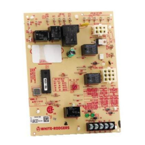
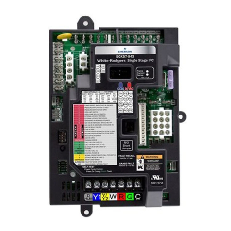
21M51U-843 UNIVERSAL INTEGRATED HSI
FURNACE CONTROL KIT
Replaces White-Rodgers 50M51-242 and 50M61-XXX's Two-Stage
HSI Systems with 80V or 120V Ignitors
FEATURES
•120VAC3-speedPSC(PermanentSplitCapacitor)circulatoroutput,two-speed
inducer output, two-stage gas valve output.
•Pushbuttonfaulthistoryretrieval.
•FurnacestatusLED–tri-color(green,redandamber).
•Heatfanoffdelay(dipswitchselectable),fanondelayforcooling.
•Autosecondstagedelay(dipswitchselectable).
•120VAChumidieroutput/120VACelectronicaircleaneroutput.
SPECIFICATIONS
Electrical Rating:
Input Voltage.................... 24 VAC, 60 Hz (Class II transformer required)
Nom. Input Current @ 24 VAC ...... 530mA+MV
Relay Load Ratings:
Gas Valve Relays ................ 1.5 amps @ 24 VAC, 60 Hz
Inducer Relays . . . . . . . . . . . . . . . . . . 2.2 FLA – 3.5 LRA @ 120 VAC
Circulator Relays ................ 14.5 FLA – 25.0 LRA @ 120 VAC
HumidierLoad ................. 1.0 amp max. @ 120 VAC
Electronic Air Cleaner Load ........ 1.0 amp max. @ 120 VAC
Ignitor Relay .................... 4.0 amps max. @ 132 VAC, 60 Hz
Flame Current Requirements:
Minimumcurrenttoinsureamedetection 0.3 µa DC*
Maximum current for non-detection .. 0.1 µa DC*
Maximumallowableleakageresistance100Mohms
*Measured with a DC microameter in the flame probe lead
Operating Temperature Range ...... -40o to 175oF (-40 to 80oC)
Humidity Range ................. 5% to 93% relative humidity (non-condensing)
Flame Failure Response Time . . . . . . 2.0 sec. max. @ 60Hz
TECHNICAL HELP
Wiring Diagram/Operation .............. See pages 179–180
TWO-STAGE
INTEGRATED 3-SPEED (PSC)
HSI FURNACE CONTROL
UNIVERSAL
REPLACEMENT
www.white-rodgers.com 45
HEATING
INTEGRATED
FURNACE CONTROLS
21M51U-843 WIRING
AND CONFIGURATION
HOT
(LINE)
50M51-843 TYPICAL WIRING DIAGRAM
NEUTRAL
(LINE)
120 VAC
24 VAC CLASS II
TRANSFORMER
50M51-843
24 VAC
TH TR
COOL
PARK
HEAT LO
HEAT HI
LINE
XFMR
EAC
HUM
CIRCU-
LATOR
BLOWER
INDUCER
HUMIDIFIER
(OPTIONAL)
ELECTRONIC
AIR CLEANER
(OPTIONAL)
IGNITOR
IGN
IND HI
IND LO
IND N
IGN N
CIRC N
LINE N
XFMR N
HUM N
EAC N
R
W2
W1
Y
YLO
R
W2
W1
Y2
Y1
COMPRESSING
UNITS
50M51-843
in other
furnace
(Trane
application)
THERMOSTAT
FLAME
SENSOR
PROBE
(Lennox only)
2ND STAGE PRESSURE
SWITCH (N. O.)
HIGH LIMIT
(N. C.)
AUX. HIGH
LIMIT (N. C.)
1ST STAGE PRESSURE
SWITCH (N. O.)
GAS
VALVE
HLO
HLI
FP
PS1
MVL
MVH
GND
GND
PS2
MV COM
TR
TH
Low Voltage (24 VAC)
Line Voltage (120 VAC)
GG
ROLLOUT
SWITCH (N. C.)
LEGEND
N. C. = Normally closed switch
N. O. = Normally open switch
TWIN
C
Twin
Application
Only
FP2
www.white-rodgers.com 179
TECHNICAL HELP
LAST FAULT MODE
To retrieve fault codes, push and release the "LAST ERROR"
button for more than 1/5 second and less than 5 seconds.
(Control will indicate this period by solid GREEN for 1/5 to
5seconds).TheLEDwillashuptovestoredfaultcodes,
beginning with the most recent. If there are no fault codes in
memory,theLEDwillashtwogreenashes.Thecontrolwill
ashthemostrecenterrorrstandtheoldesterrorlast(lastin
rstout).Thereshallbe2secondsbetweencodes.SolidLED
error codes will not be displayed.
DIAGNOSTIC FEATURES
The 50M51 control continuously monitors its own operation and
the operation of the system. If a failure occurs, the red LED on the
controlwillashafailurecode.If the failure is internal to the
control, the light will stay on. In this case, the entire control
should be replaced, as the control is not eld-repairable.
If the sensed failure is in the system (external to control), the
LEDwillashinthefollowingash-pausesequencestoindicate
failurestatus(eachashwilllastapproximately0.25seconds,
and each pause will last approximately 2 seconds.)
During a second-stage error condition, the red LED when in
lockoutwillashgroupsofdoublepulses.TheredLEDwillash
on for approximately 1/15 second then off for 1/15 second then
on for 1/15 second, then off for 3/10 second.The pause between
groupsofashesisapproximately2seconds.
DIAGNOSTIC TABLE
Green
LED
Flash
Amber
LED
Flash
Red LED
Flash Error/Condition Comments/Troubleshooting
1Flamesensedwhennoameshould
be present
Verify the gas valve is operating and shutting down properly. Flame in burner
assembleshouldextinguishpromptlyattheendofthecycle.Checkoricesand
gas pressure.
2Pressureswitchstuckclosed/inducererror Pressureswitchstuckclosed.Checkswitchfunction,verifyinduceristurningoff.
31st-stagepressureswitchstuckopen/inducer
error
Checkpressureswitchfunctionandtubing.Verifyinduceristurningonthepulling
sufcientvacuumtoengageswitch.
4 Open limit switch Verify continuity through rollout switch circuit.
5 Open rollout/open fuse detect Verifycontinuitythroughrolloutswitchcircuit,checkfuse.
61st-stagepressureswitchcyclelockout iftherststagepressureswitchcycles5times(open,closed)duringonecall
forheatfromthethermostatthecontrolwilllockout.Checkpressureswitchfor
uttering,inconsistentclosureorpoorvacuumpressure.
7Externallockout(retries) Failuretosenseameisoftencausedbycarbondepositsontheamesensor,a
disconnectedorshortedamesensorleadorapoorlygroundedfurnace.Carbon
deposits can be cleaned with emery cloth. Verify sensor is not contacting the
burnerandislocatedinagoodpositiontosenseame.Checksensorleadfor
shorting and verify furnace is grounded properly.
8Externallockout(ignitionrecyclesexceeded
whereameisestablishedandthenlost) Checkitemsforexceededretrieslistedaboveandverifyvalveisnotdroppingout
allowingametobeestablishedandthenlost.
9 Grounding or Reversed polarity Verifythecontrolandfurnaceareproperlygrounded.Checkandreversepolarity
(primary) if incorrect.
10 Module gas valve contacts energized with no
call for heat
Verify valve is not receiving voltage from a short. If a valve wiring is correct and
condition persists, replace module.
11 Limit switch open – possible blower failure
overheating limit
Possibleblowerfailure,restrictedairowthroughapplianceorductwork.Verify
continuity through limit switch circuit and correct overheating cause.
12 Module Ignitor contact failure Fault code indicates the module ignitor contacts are not functioning properly.
Replace module.
Solid Module - internal fault condition Module contacts for gas valve not operating or processor fault. Reset control. if
condition persists replace module.
Rapid Twinning error Checkwireconnections.Ifconditionpersists,replacemodule.
3 double 2nd-stagePressureSwitchStuckOpen/Inducer
Error
Checkpressureswitchfunctionandtubing.Verifyinduceristurningonand
pullingsufcientvacuumtoengageswitch.
1NormalOperationwithcallforrststageheat Normaloperation-rststage
2Normal Operation with call for second stage heat Normaloperation-rststage
3 W2 present with no W1 Secondstagecallforheatonthermostatcircuitwithnocallforrststage.Verify
dipswitchesaresetfortwostagethermostatandcheckthermostatrststage
circuit.Conguredforamulti-stagethermostattheModulewillnotinitiateheating
unlessrststagecallfromthermostatisreceived.
4YpresentwithnoGcall Modulewillallowcoolingtooperatewithonlya"Ysignalfromthethermostatbut
willalsotriggerthiscode.Verifythermostatisenergizingboth"Y"and"G"oncall
forcool.Check"G"terminalconnections.
Rapid Lowamesensecurrent Lowamesensecurrentisoftencausedbycarbondepositsontheamesensor,
apoorlygroundedfurnaceoramis-alignedamesenseprobe.Carbondeposits
canbecleanedwithemerycloth.Checkforimprovefurnaceandmoduleground.
Verifysensorislocatedinorverynearameasspeciedbytheappliance
manufacturer.
1 Standby or Call for Cool Normal operation. Waiting for call from thermostat or receiving thermostat
call for cool.
INTEGRATED
FURNACE CONTROLS
21M51U-843
DIAGNOSTIC TABLE
www.white-rodgers.com
180
TECHNICAL HELP
Other White Rodgers Controllers manuals

White Rodgers 50A55-843 User manual

White Rodgers

White Rodgers 50A55-843 User manual

White Rodgers 50A62-820 User manual

White Rodgers

White Rodgers 50A62-820 User manual

White Rodgers 1145 User manual

White Rodgers

White Rodgers 1145 User manual

White Rodgers 1127 User manual

White Rodgers

White Rodgers 1127 User manual

White Rodgers 50A55-843 User manual

White Rodgers

White Rodgers 50A55-843 User manual

White Rodgers 50X57-843 User manual

White Rodgers

White Rodgers 50X57-843 User manual

White Rodgers 668-430 User manual

White Rodgers

White Rodgers 668-430 User manual

White Rodgers UNIVERSAL INTEGRATED FURANCE CONTROL... User manual

White Rodgers

White Rodgers UNIVERSAL INTEGRATED FURANCE CONTROL... User manual

White Rodgers 50M56-743 User manual

White Rodgers

White Rodgers 50M56-743 User manual

White Rodgers 50A55 User manual

White Rodgers

White Rodgers 50A55 User manual

White Rodgers 50M58-707 User manual

White Rodgers

White Rodgers 50M58-707 User manual

White Rodgers 5D51-35 User manual

White Rodgers

White Rodgers 5D51-35 User manual

White Rodgers 24A06G-1 User manual

White Rodgers

White Rodgers 24A06G-1 User manual

White Rodgers 50M56U-751 User manual

White Rodgers

White Rodgers 50M56U-751 User manual

White Rodgers 50M58-289 User manual

White Rodgers

White Rodgers 50M58-289 User manual

White Rodgers 1F98EZ-1621 User manual

White Rodgers

White Rodgers 1F98EZ-1621 User manual

White Rodgers 50A55-143 User manual

White Rodgers

White Rodgers 50A55-143 User manual

White Rodgers 668 User manual

White Rodgers

White Rodgers 668 User manual

White Rodgers 11E79 User manual

White Rodgers

White Rodgers 11E79 User manual

White Rodgers 50M56U-751 User manual

White Rodgers

White Rodgers 50M56U-751 User manual

White Rodgers 37C73U User manual

White Rodgers

White Rodgers 37C73U User manual

White Rodgers 50T35-743 User manual

White Rodgers

White Rodgers 50T35-743 User manual

White Rodgers 1131 User manual

White Rodgers

White Rodgers 1131 User manual

Popular Controllers manuals by other brands

Micronor MR340-1 instruction manual

Micronor

Micronor MR340-1 instruction manual

Nastec HMA Series operating manual

Nastec

Nastec HMA Series operating manual

Emerson Tartarini PRX Series instruction manual

Emerson

Emerson Tartarini PRX Series instruction manual

Wilo IR-Monitor Installation and operating instructions

Wilo

Wilo IR-Monitor Installation and operating instructions

Honeywell UDC3500 product manual

Honeywell

Honeywell UDC3500 product manual

Galil DMC-2X00 user manual

Galil

Galil DMC-2X00 user manual

Watts N45B Series installation instructions

Watts

Watts N45B Series installation instructions

Samson 3374-10 Mounting and operating instructions

Samson

Samson 3374-10 Mounting and operating instructions

Nymet WaterMe user manual

Nymet

Nymet WaterMe user manual

ICM Controls ICM271 Installation, operation & application guide

ICM Controls

ICM Controls ICM271 Installation, operation & application guide

Konig & Meyer 18819 manual

Konig & Meyer

Konig & Meyer 18819 manual

DEL-AIR SR-242 user guide

DEL-AIR

DEL-AIR SR-242 user guide

SmartHardware STR1000008X manual

SmartHardware

SmartHardware STR1000008X manual

Planar PU-16 manual

Planar

Planar PU-16 manual

SMC Networks LEL25M Operation manual

SMC Networks

SMC Networks LEL25M Operation manual

Emerson CSB700 Series instruction manual

Emerson

Emerson CSB700 Series instruction manual

Hobym Observatory Titian TCS user manual

Hobym Observatory

Hobym Observatory Titian TCS user manual

Omega CN3440 SERIES user guide

Omega

Omega CN3440 SERIES user guide

manuals.online logo
manuals.online logoBrands
  • About & Mission
  • Contact us
  • Privacy Policy
  • Terms and Conditions

Copyright 2025 Manuals.Online. All Rights Reserved.