EVR-Series Installation and Operating Instructions 2 1/12/12
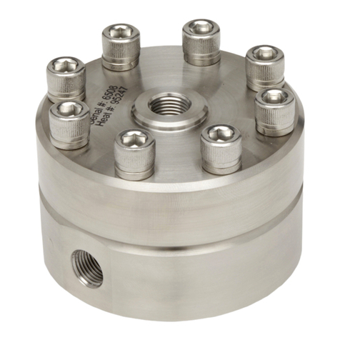
GS & Instrument Body Re-Build Instructions (Main Regulator Body Only)
1. Lay Reference Cap upside down with screws & washers
inserted
2. Carefully place O-ring inside groove of Reference Cap.
3. Inspect diaphragm for any damage. Replace if any question on
condition.
4. Lay diaphragm down onto Reference Cap and through screws.
5. Place Body (upper side with small holes) onto Reference Cap,
aligning screws.
6. Add remaining screws & washers.
7. Compress assembly and screw on nuts. Tighten gradually in
opposing patterns.
8. Tighten all nuts to specified torque:
•#10 or M5 screws = 55-65 in-lbf torque (6.2-7.3 N-m)
•¼” or M6 screws = 65-77 in-lbf torque (7.3-8.7 N-m)
•Note: Gap between sections should be even, but will not disappear
NLB Body Re-Build Instructions (Main Regulator Body Only)
1. Note: During disassembly, carefully note location of key
components.
2. Lay Top Cap upside down with screws & lock washers
inserted.
3. Carefully place O-ring inside groove of Top Cap.
4. Inspect diaphragm for any damage (nicks, cuts, or holes).
Lay diaphragm down on Top Cap and through screws.
5. Insert alignment sleeves around every other screw. (Note:
these sleeves are used to assure perfect centering of
Center Plate and Top Cap.)
6. Place Center Section onto Reference Cap and inside
screws. The top of the Center Plate goes down toward Top Cap (the top of the Seat Plate has
either grooves or a dished recess; the bottom of the Seat Plate is always flat)
7. Rotate Center Plate so that the larger inlet holes or inlet arcs are centered between two bolt holes
on the Top Cap.
8. Insert both o-rings into the grooves on the Lower Body. Use O-ring grease or Vacuum grease to
hold these o-rings in place (as it will be inverted).
9. Invert Lower Body onto screws and assembly ensuring that the Inlet elbow (marked with “I”) is
placed over the larger inlet holes or inlet arcs.
10. Ensure that the o-rings stayed in place by verifying that assembly has an even gap between Top
Cap and Bottom Body.
11. Thread nuts onto screws and gradually tighten in opposing patterns
12. Tighten all nuts to specified torque:
•#10 or M5 screws = 55-65 in-lbf torque (6.2-7.3 N-m)
•¼” or M6 screws = 65-77 in-lbf torque (7.3-8.7 N-m)
Contact factory for replacement diaphragms or for additional maintenance or assembly instructions.
Important notes: Sensitive diaphragms and seals can leak. It is the responsibility of the end user to
use this product in a way that prevents injury to persons and property.See Standard Terms and
Conditions for important Limitation of Liability notes.
