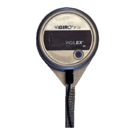
STIF VIGIRO SV26 User manual

INSTRUCTION MANUAL
GB
–
1/5
www.stifnet.com - DOC NO. BE0455062-B
USE
- The purpose of the
VIGIRO
®
SV26 is to control the constant speed of a rotating shaft, so as to identify any
abnormality in dangerous underspeed.
- The VIGIRO
®
SV26 incorporates a programmable rotation controller for thresholds of -33%/-20%/-11%/-6%
underspeed. It is commonly installed on bucket elevators, chain conveyors, mixers, rotary valves, belt conveyors,
etc.
-
The VIGIRO
®
SV26 is fixed directly at the end of the shaft by an M12 tapping for the standard version or M10 on
request, either with the EAZY-FIX (magnetic fixation) for a quick commissioning without tapping.
DESCRIPTION
- The VIGIRO
®
SV26 is a compact device composed of the following elements:
1. Protection skin in stainless steel.
2. Connecting cable 2m ( or 3 wires).
3. Standard M12 threaded rotation axis (M10 on request) for fixing at the end of the shaft.
4. Anti-rotation strap.
5. Detectable 2-blade propeller (optional 4-blade propeller) located inside the protection.
6. Transparent window.
7. Programming button access screw.
8. SENSOR screwdriver
Possible adjustment of the VIGIRO
®
SV26
- Rotation frequency to respect 0.5... 500 rpm or 1... 1000 pulses/min.
Z.A. de la lande
-
49170 Sain
-
Georges
-
sur
-
Loire
-
France
Head office, purchasing and fac ory: tel: +33 2 41 72 16 80 - ax +33 2 41 72 16 85
France Expor Sales Service: tel.: +33 2 41 72 16 82 - ax +33 2 41 39 32 12
email: sales@stifnet.com
- Website:
www.stifnet.com
SAS with a capital of
€ 800,000
-
R.C.S. Angers B 328 876 503
-
84B12 APE 2511Z
-
VAT number R 35 328 876 503
The SENSOR screwdriver allows with its upper part to currency the screw of access to the
sensor. The lower part of the screwdriver allows to trigger the learning of the sensor.
1
2
3
4
5
6
7
8

INSTRUCTION MANUAL
GB
–
2/5
www.stifnet.com - DOC NO. BE0455062-B
Scheme A
18
M12/M10
Pulley shaft
Thread lock
PRECAUTIONS
The VIGIRO
®
SV26 must be installed, connected and put into service only by competent personnel. The staff must have
electrical authorizations, know the regulations and provisions concerning the installation of these devices, in particular
for the Ex II3D version integrated into ATEX zones.
- Carry out beforehand an electrical connection study to install the VIGIRO
®
SV26 (standardized electrical diagram,
power supply and electrical protection, plc control, ATEX zones).
- Define the under-speed threshold to be applied to secure the bucket lift or belt conveyor in order to avoid any risk of
heating (example: Engine stop underspeed threshold defined at 6% between the speed observed on the pulley
driven and the nominal speed of the motor pulley).
- Check that the temperature range of use of the VIGIRO® SV26 (variable according to version) corresponds to that
of your application.
- Check during the first commissioning of the bucket lift in the handling phase that the VIGIRO® SV26' remains
stationary and held by its anti-rotation strap (only the axis of the VIGIRO® SV26 must be rotated).
- Shut down the bucket lift or belt conveyor to a standstill (off) before any installation or intervention on the VIGIRO®
SV26 (intervention information to be indicated on the machine).
Optional (magnetic fixation without tapping) :
The EAZY-FIX can’t be installed on a stainless-steel shaft.
Ensure that the bearing surface of the shaft is clean and plane.
Take precaution during installation of the EAZY-FIX because its very strong magnetic force of
attraction can cause pinching injury.
CAUTION… The magne ic field of he EAZY-FIX may damage some sensi ive
sys em such as magne ic racks or apes, cer ain wa ches, e c…
INSTALLATION
Assembly without EAZY-FIX
Perform a M12 tapping (optional M10) at the end of the pulley shaft with a minimal depth of 18mm following Scheme
A (Be careful to center the tapping to avoid eccentricity effects in service).
Coat the tapping with removable thread locker, then screw the VIGIRO
®
SV26 on the pulley shaft with a 16mm
open-end wrench.
Make sure to respect the setting time of the thread lock before using it for the first time.
Assembly with EAZY-FIX (optional)
Coat the tapping with removable thread locker of the optional EAZY-FIX, then screw the VIGIRO
®
SV26 on the EAZY-FIX
with a 16mm open-end wrench.
Make sure to respect the setting time of the thread lock before using it for the first time.
Finish by fixing the anti-rotation strap without creating tension between the VIGIRO
®
SV26 and the anchor point.
(M12)
Thread lock
Magnetic hold
at the end of the shaft

INSTRUCTION MANUAL
GB
–
3/5
www.stifnet.com - DOC NO. BE0455062-B
Electrically connect the VIGIRO SV26® by respecting the electrical scheme B or C and the operating conditions
depending on the version used, 2-wire or 3-wire:
PROGRAMMATION
Application of the previously defined underspeed threshold -33%, -20%, -11% or -6% in advance to stop the handling
equipment in a proven fault situation.
1) Remove the access screw to the learning button with the upper part of the screwdriver (available on the base of
the VIGIRO SV26
®
), then store the access screw in a safe place during all learning stages.
2) Run the handling equipment until a stable speed is reached.
3) Switch on the VIGIRO SV26
®
.
4) The first learning step is to record the rated speed of the handling device, to do this insert the narrow end of
the screwdriver into the access hole then press and hold the button until the green LED goes out for 3 seconds,
when the green LED comes back on release the button.
The green LED flashes slowly and then lights up to indicate that the speed learning is successful.
At this step, the default underspeed threshold is -33% (e.g. if the nominal speed is 180 rpm, the detector
output will be deactivated when the underspeed is reduced below the threshold ≤120 rpm).
5) After learning the nominal speed (active underspeed -33%), it is possible to fine-tune the underspeed setting
by programming a more restrictive threshold at -20%, -11% or -6%.
The underspeed thresholds of -20%, -11% or -6% are available by performing one training session after
another. For example, it takes three successive learnings to reach the -6% threshold.
2
-
wire branch scheme
C
Coulours
BN = Brown
BU = Blue
GR = Green (not used)
PVC cable 2m non-ATEX
zone 2x0.34mm²
3
-
wire/NC connec ion scheme B
Colours
BN = Brown
BU = Blue
WH = White
BK = Black (Do not used)
PVC cable 2m for ATEX area
and not
ATEX 3x0.34mm²
For low vol age sensor, ATEX or no
-3-wire cable connec ion
-L=2m cable
-Vol age 12-24V DC
-Vol age limi s, including ripple, 10-36V DC
-Swi ching power ≤ 100mA
-empera ure Opera ing: -25... 70°C
-empera ure Opera ing: -20... 60°C (ATEX)
-Pro ec ion - IP67
Cau ion: Any connec ion mus be made ou side he
ATEX zone
For mul i
-
vol age sensor, ou of ATEX zone
-2-wire cable connec ion
-L=2m cable
-Vol age 24... 240V AC/DC
-Vol age limi s, ripple included 20... 264V AC/DC
-Residual vol age a nominal I ≤5.5V
-Swi ching power 5... 1.00 mA AC/DC
-empera ure Opera ing: -25... 70°C
-Pro ec ion - IP68
I is impera ive o pu in series wi h he load a
fas -ac ing fuse of 0.4A
WH/2 (NC)

INSTRUCTION MANUAL
GB
–
4/5
www.stifnet.com - DOC NO. BE0455062-B
To program the underspeed threshold to -20%, press and hold the button until the green LED goes out for 3
seconds, when the green LED lights up again, release the button.
The green LED flashes once to indicate that the underspeed threshold is set to -20% (see scheme D).
To program the underspeed threshold at -11% or -6% proceed successively in the same way as for -20%.
Note: To program a new underspeed threshold or a new speed, please repeat all the programming steps
starting with a reset
1) To perform the Reset, please press and hold the button until the green LED goes out for 3 seconds, when the
green LED lights up again, continue to hold the button for 4 seconds until the green LED goes out and then
release the button. The detector is now without an underspeed program.
% programmable underspeed
-33% by default, after learning the nominal speed
-20% 1"flash green"
-11% 2"flash green"
-6% 3"flash green"
Scheme
D
Replace the access screw
to the learning button after
programming
Green LED
observation Porthole
1
flash
3s
2
flash
3s
3 flash
3s
=
Ok
=
Ok
=
Ok
-
20%
-
11
%
-
6
%
Rese
=
Reste
Ok
3s
4s

INSTRUCTION MANUAL
GB
–
5/5
www.stifnet.com - DOC NO. BE0455062-B
CONTROL & PERIODIC MAINTENANCE
1) To ensure the functional integrity of the VIGIRO
®
SV26, you must scheduleperiodic inspections. The frequency of
inspections must be sufficient to avoid dangerous situations (situations that affect the intrinsic operation of the
VIGIRO
®
SV26).
2) During these inspections, check that the VIGIRO
®
SV26 is not affected by the following defects: dust layer >2mm,
fixing the axis of the VIGIRO
®
SV26, degraded or unfixed anti-rotation strap, non-operational power-on LEDs,
degraded electrical wiring, shocks on the envelope of the VIGIRO
®
SV26, etc...
3) In the case of one or more defects found, you must proceed with the restoration in order to correct the defect(s)
before you can use the bucket lift or belt conveyor again.
4) Only personnel trained and authorized in maintenance procedures forequipment are able to carry out inspections of
the VIGIRO
®
SV26.
5) The output of the VIGIRO SV26® remains closed for 9 seconds to allow the handling equipment to reach its rated
speed
DISPOSAL
When dismantling the VIGIRO
®
SV26, the user must ensure the proper disposal of this device and hand over to
the specialized harvesting centers the components according to their nature (stainless steel, electrical
equipment, seal, etc.).
In the event that the VIGIRO
®
SV26 is used, controlled, under conditions contrary to the precautions described in
this instruction manual, STIF declines all responsibility for damage caused to man, animal, environment, material
property.
Table of contents
Other STIF Controllers manuals
