Equip 1000VA User manual
USER MANUAL
Line Interactive UPS
1000VA/1500VA/2000VA/3000VA
Uninterruptible Power Supply System
Copyright © Digital Data Communications GmbH, Germany. All Rights Reserved.

IMPORTANT SAFETY
INSTRUCTIONS
SAVE THESE INSTRUCTIONS
This manual contains important instructions for
1000VA/1500VA/2000VA/3000VA series that should be
followed during installation and maintenance of the UPS
and batteries. Please read all safety and operating
instructions before operating the UPS. Adhere to all
warnings on the unit and in this manual. And follow all
operating and user instructions.

CONTENTS
1. Introduction ············································································· 1
2. Safety Warning ········································································· 2
2.1 Description of Commonly Used Symbols···································· 3
3. Installation ··············································································· 4
3.1 Inspection of Unit ·································································· 4
3.2 Unpacking the Cabinet ··························································· 4
3.3 UPS Setup··········································································· 4
3.4 EBM Installation (Optional)······················································ 8
3.5 UPS Initial Startup ······························································· 14
4. Operation··············································································· 15
4.1 Display Panel ····································································· 15
4.2 Operating Mode ·································································· 19
4.3 Configuring Load Segment···················································· 19
4.4 Configuring UPS for EBM Numbers ········································ 20
4.5 Configuring Green Function··················································· 21
5. Communication Port ······························································· 22
5.1 RS-232 and USB Communication Ports ··································· 22
5.2 Emergency Power Off (EPO) ················································· 22
5.3 Network Management Card (Optional)····································· 23
6. UPS Maintenance···································································· 24
6.1 UPS and Battery Care·························································· 24
6.2 Storing the UPS and Batteries ··············································· 24
6.3 Time to Replace Batteries ····················································· 24
6.4 Replacing UPS Internal Batteries············································ 25
6.5 Testing New Batteries ·························································· 27
6.6 Recycling the Used Battery: ·················································· 27
7. Specification ·········································································· 28
7.1 Specification······································································· 28
7.2 Rear Panels ······································································· 30
8. Trouble Shooting ···································································· 33
8.1 Audible Alarm Trouble Shooting ············································· 33
8.2 General Trouble Shooting ····················································· 33
9. Software Installation ······························································· 34

1
1. Introduction
This line-interactive series is compact and pure sine wave UPS and it is
designed for essential applications and environment, such as desktops,
servers, workstations, and other networking equipments. These models are
available in the output ratings of 1000VA, 1500VA, 2000VA and 3000VA.
The series protects your sensitive electronic equipments against power
problems including power sags, spike, brownouts, line noise and blackouts.
The series is convertible to rack and tower forms. It can be placed either in
Rack 2U or Tower form. The front panel of the UPS includes LCD display
and four control buttons that allow users to monitor, configure and control
the units. On LCD, it also includes a LCD graphical bar, two status
indications and four alarm indications. A control button from the front panel
allows users to silence off the AC fail alarm and initiate the UPS self test
sequence as well. The UPS case for 1000VA ~ 3000VA is made of metal.
This series is powered from the AC mains and supply AC outputs via
receptacles on the rear panel. Communication and control of UPS is
available through serial or USB ports located on the rear panel. The serial
port will support communications directly with a server.
Features:
!Microprocessor control guarantees high reliability
!High frequency design
!Built-in boost and buck AVR
!Easy battery replacement design
!Selectable input and output range
!Cold start capability
!Built-in Dry contact/RS-232/USB communication port
!SNMP allows for web-based remote or monitoring management
!Enable to extend runtime with scalable external battery
module(EBM)
!Overload, short-circuit, and overheat protection
!Rack/Tower 2 in 1 Design
!19 inches rack mount available for all models

2
2. Safety Warning
DANGER:
This UPS contains high voltages. All repairs and service should be
performed by authorized service personnel only. There are no user
serviceable parts inside the UPS.
WARNING:
!This UPS contains its own energy source (batteries).The UPS output
may carry live voltage even when the UPS is not connected to an AC
supply.
!To reduce the risk of fire or electric shock, install this UPS in a
temperature and humidity controlled, indoor environment, free of
conductive contaminants.(Ambient :0-40°C)
!To reduce the risk of fire, connect to a circuit breaker provided with 20
amperes maximum branch circuit over-current protection.
!To comply with international standards and wiring regulations,
the sum of the leakage currents of the UPS and the connected loads
must not exceed 3.5mA.
!The socket outlet that supplies the UPS shall be installed near the
UPS and shall be easily accessible.
!Protective earthling connections shall be such that disconnection of a
protective earth should be made at one point that is the furthest away
from the UPS, maintaining the dedicated line in order to secure
equipotential connection.
!The UPS and EBMs connected in series should be installed closely
such that the operators can not touch the interconnecting wire which
is basic insulated from primary circuit.
CAUTION:
!Batteries can present a risk of electrical shock or burnt from high
short-circuit current. Observe proper precautions. Servicing should be
performed by qualified service personnel knowledgeable of batteries
3
and required precautions. Keep unauthorized personnel away from
batteries.
!Proper disposal of batteries is required. Refer to your local codes for
disposal requirements.
!Never dispose of batteries in a fire. Batteries may explode when
exposed to flame.
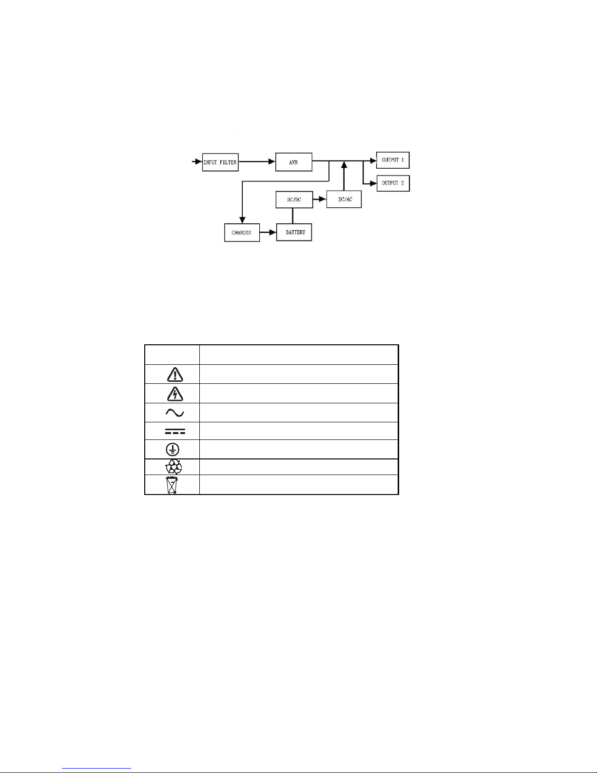
Following figure shows the basic internal circuit configuration of the UPS
2.1 Description of Commonly Used Symbols
Some or all of the following Notations may be used in this manual and may
appear in your application process. Therefore, all users should be familiar with
them and understand their explanations.
Table1. Description of Commonly Used Symbols
Symbol
Description
Alert you to pay special attention
Caution of high voltage
Alternating current source (AC)
Direct current source(DC)
Protective ground
Recycle
Keep UPS in a clear area

4
3. Installation
3.1 Inspection of Unit
Inspect the UPS upon receiving. If the UPS is apparently damaged during
the shipment, please keep the box and packing material in original form for
the carrier and notify the carrier and dealer immediately.
3.2 Unpacking the Cabinet
To unpack the system:
1. Open the outer carton and remove the accessories packaged with the
cabinet.
2. Carefully lift the cabinet out of the outer carton and set it on a flat, stable
surface.
3. Discard or recycle the packaging in a responsible manner, or store it for
future use.
3.3 UPS Setup
All model series are designed for tower and rack purpose. They can be
installed into a 19 inches equipment rack. Please follow the instruction for
Tower Setup and Rack-Mount Setup.
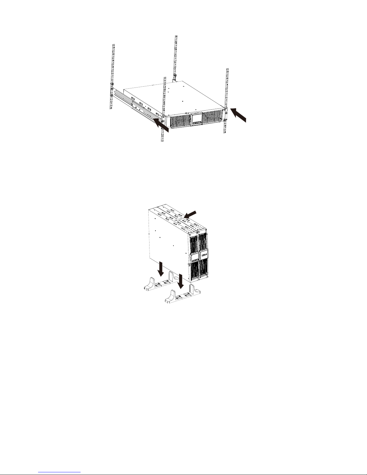
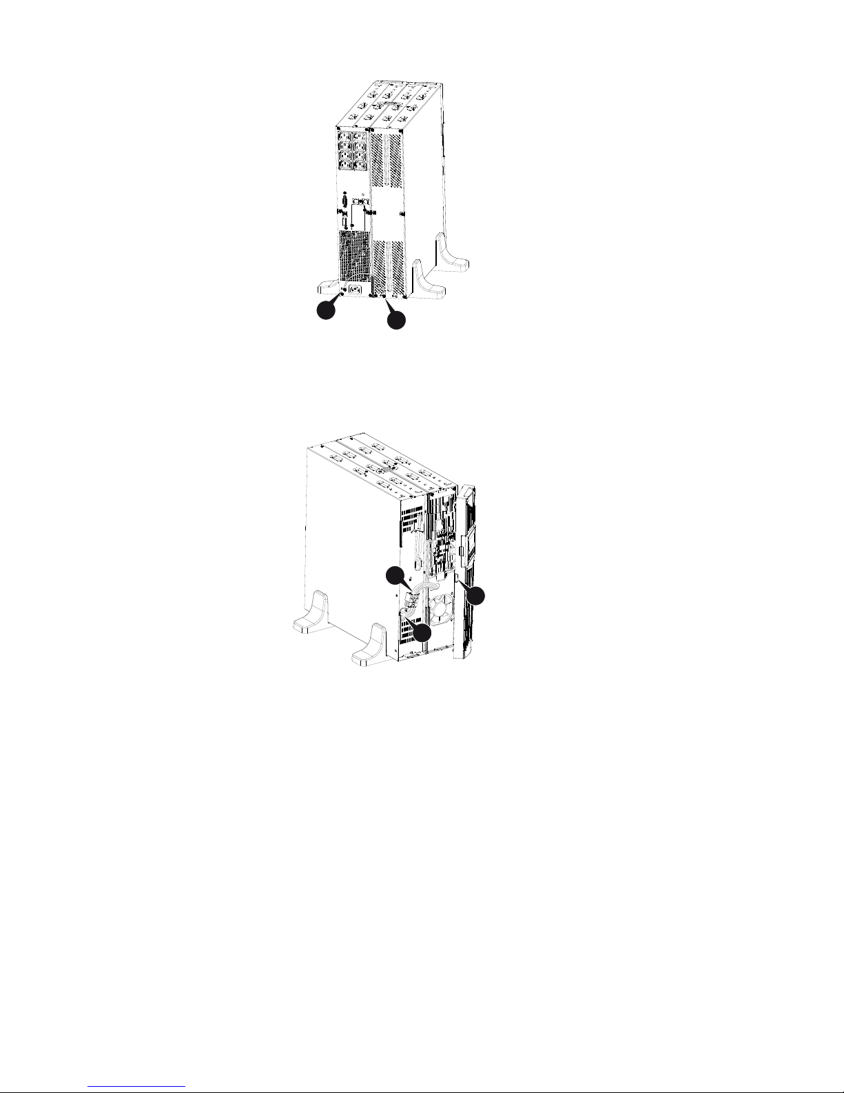
"Tower setup
This series of UPS can be placed horizontally and vertically. As a tower
configuration, it is provided with the optional UPS stands to stabilize the
UPS when the UPS is positioned in vertical. The UPS stand must be
attached to the bottom of the tower.

5
Use the following procedure to install UPS in UPS stands.
1. Slide down the UPS vertically and put two UPS stands at the end of the
tower.
2. Place down the UPS into two stands carefully.

6
3. Pull out the LCD box and rotate it in a clockwise direction to 90 degree
and then push it back in the front panel.
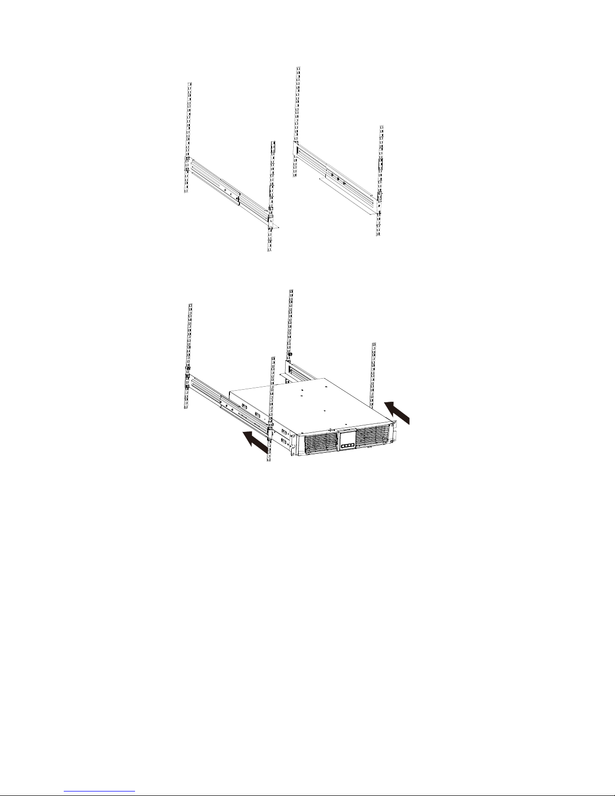
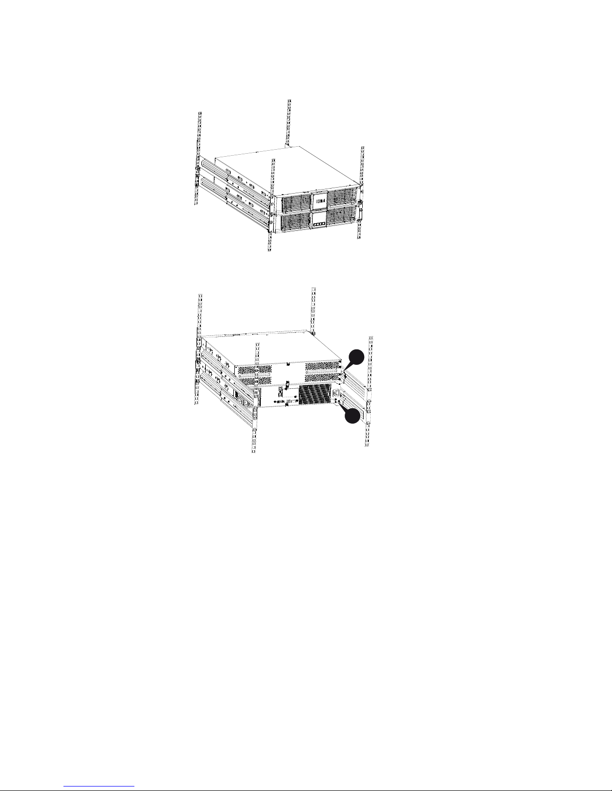
"Rack-mount setup
The series can be installed in 19 inches racks. Both the UPS and external
battery enclosure need 2U of valuable rack space.
Use the following procedure to install UPS in a rack.
1. Align the mounting ears with screw holes on the side of the UPS, and
tighten the screw.
7
2. Assemble the rack rails with the rack-mounting.
3. Slide in the UPS into the rack rail and lock it in the rack enclosure.
8
4. Tighten the screw, and the load can then be connected
3.4 EBM Installation (Optional)
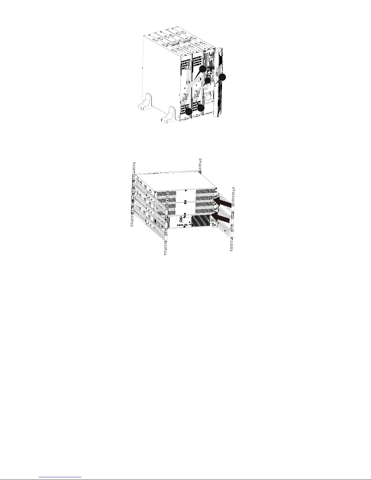
"Connecting the EBM in Tower form:
1. Slide down the UPS and EBM vertically and place two UPS stands with
the extend part at the end of the tower.
2. Tighten the screw on the metal sheet for stabilization
9
3. Connect the Earth line from UPS (port A ) to EBM (port B)
4. Take off the front panel, and connect the battery terminal (A) from UPS
to EBM terminal (B) shown as below. Users need to remove the small
gate(C) on side of the front panel to allow the outlet wire of the EBM to
pass through the gate and then reassemble front panel.
B
A
C
B
A
10
"Connecting the EBM in a rack form
1. Using the same method as assembling UPS in a rack form, assemble
EBM into the rack-mounting on the top or bottom of the UPS.
2. Connect the earth line from UPS (port A ) to EBM (port B )
A
B
11
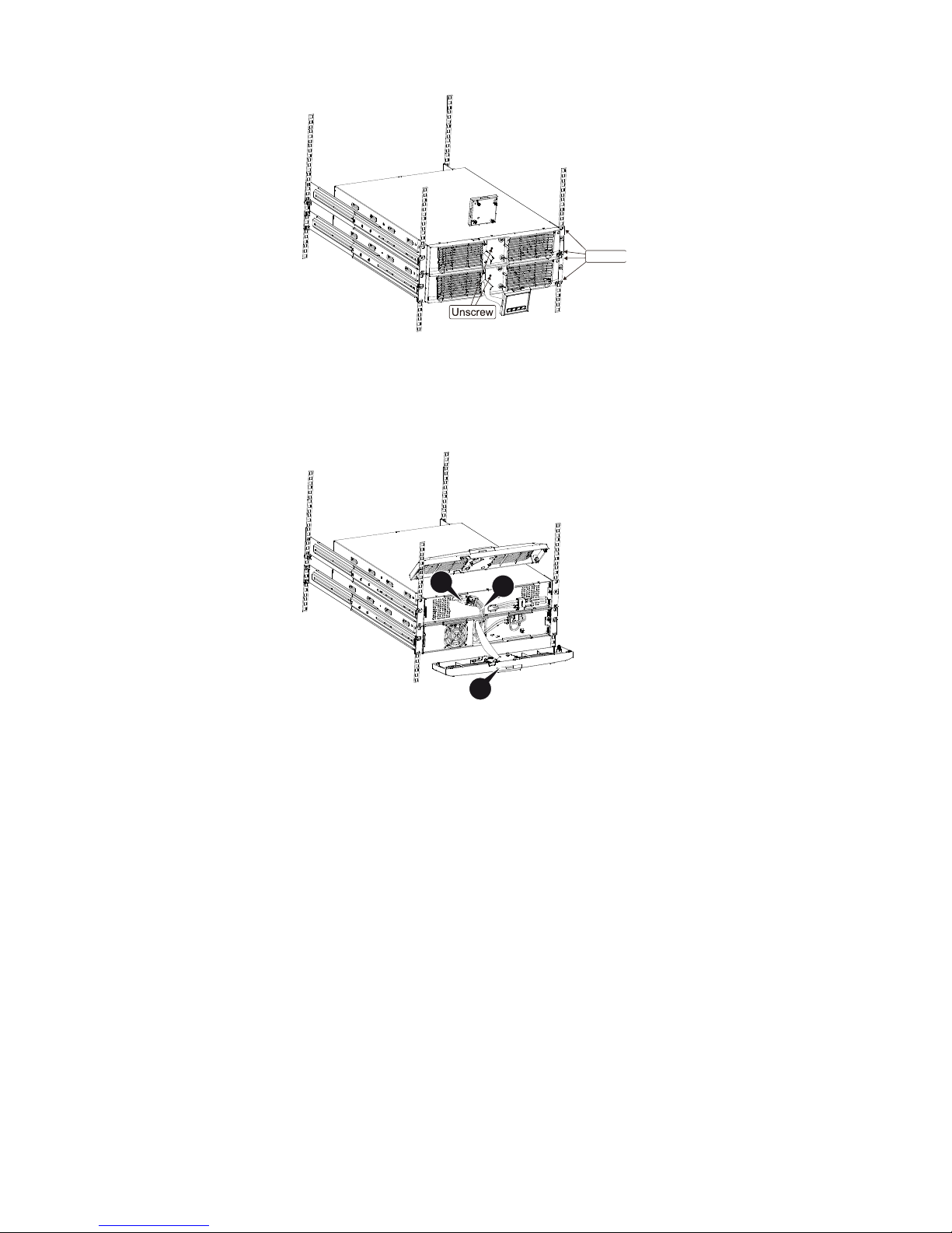
3. Take off the LCD box, and unscrew the internal screws.
4. Take off the front panel, and connect the battery terminal (A) from UPS
to EBM terminal (B) shown as below. Users need to remove the small
gate(C) on side of the front panel to allow the outlet wire of the EBM to
pass through the gate and then reassemble front panel.
5. After installing the UPS into rack, the load can then be connected to
UPS. Please make sure the load equipment is turned off before plugging
all loads into the output receptacle.
Unscrew
BA
C
12
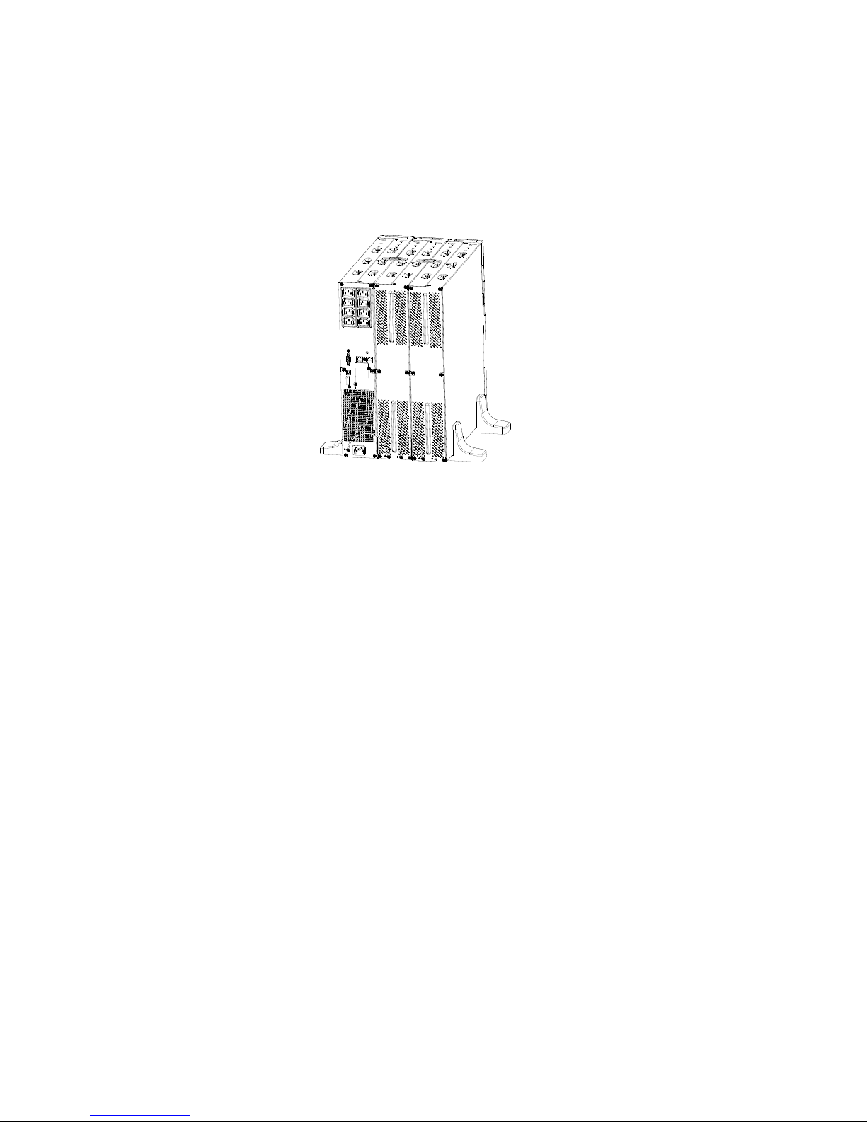
"Connecting the Multiple EBMs
1000VA/1500VA/2000VA and 3000VA UPS include external battery port
that allows users to connect multiple EBM in order to provide additional
backup time. Follow the procedure to install multiple EBM as below.
Connecting multiple EBMs in Tower form
1. Connect Earth line between UPS and the first EBM, and then connect Earth
Line between the first EBM and the second EBM.
2. Take off the front panel, and connect the battery terminal (A) from UPS to
EBM terminal (B) shown as below. And then connect the battery terminal
(D) from the first EBM to the battery terminal (E) from the second EBM.
Users need to remove the small gate(C) on side of the front panel to
allow the outlet wire of the EBM to pass through the gate and then
reassemble front panel.
13
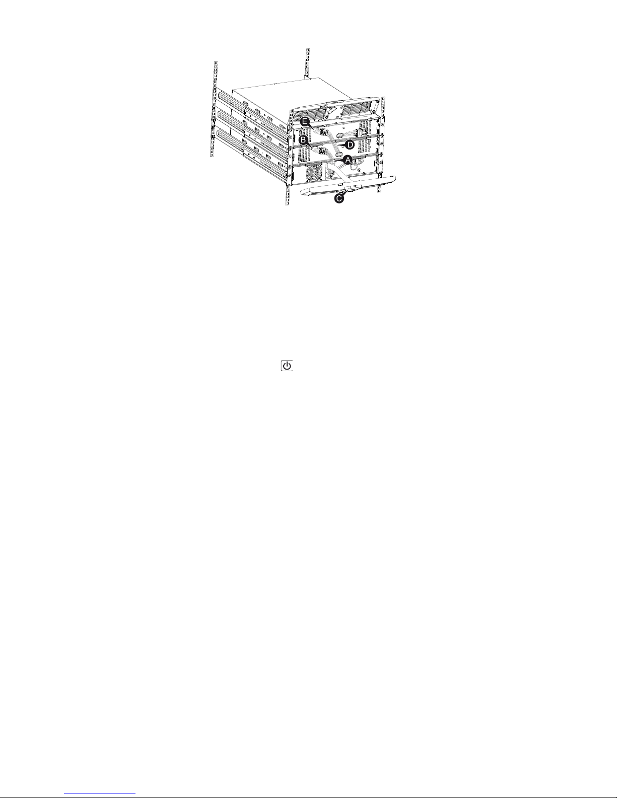
Connecting the Multiple EBMs in rack form
1. Connect Earth line between UPS and the first EBM, and then connect
Earth Line between the first EBM and the second EBM.
2. Take off the front panel, and connect the battery terminal (A) from UPS
to EBM terminal (B) shown as below. And then connect the battery
terminal (D) from the first EBM to the battery terminal (E) from the
second EBM. Users need to remove the small gate(C) on side of the
front panel to allow the outlet wire of the EBM to pass through the gate
and then reassemble front panel.
B
C
A
D
E
14
Note: Three or more EBMs can be connected to the UPS in the same way
as shown above.
3.5 UPS Initial Startup
To start up the UPS:
1. Verify that the internal batteries are connected. If optional EBMs are
installed, verify that the EBMs are connected to the UPS.
2. Plug the equipment to be protected onto the UPS, but do not turn on the
protected equipment.
3. Plug in the UPS input power cord. The UPS front panel display
illuminates and UPS status display shows “STbY”
4. Press and hold the button more than 3 seconds. The UPS status
display changes to “NORM”
6. Check the UPS display for active alarms or notices. Resolve any active
alarms before continuing. See “Troubleshooting”
8. If optional EBMs are installed, see “Configuring UPS for EBM numbers”
on page 21 to set the number of installed EBMs.
9. To change any other factory-set defaults, see “Operation”
Note: At initial startup, the UPS sets system frequency according to input
line frequency.

15
4. Operation
4.1 Display Panel
The UPS has a four-button graphical LCD with dual color backlight.
Standard back-light is used to light up the display with black text and a blue
background. When the UPS has a critical alarm, the backlight changes the
background to red. See Figure below:
"Control Buttons functions:
There are four buttons on the control panel.
ON/OFF
UPS Test /Alarm Silence
Select
Enter
16
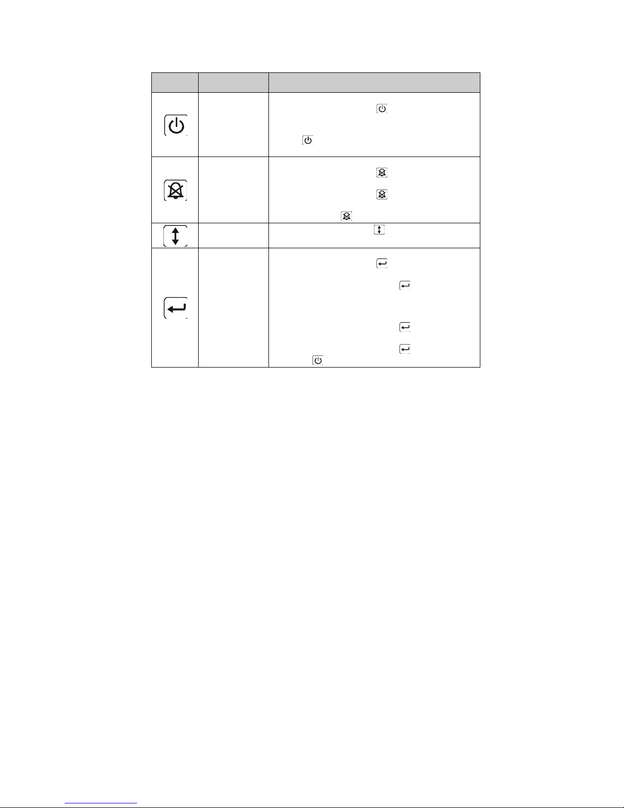
The following table describes the functions of the LCD control buttons.
Table2. Description of control button
Control
Button
Switch
Function
ON/OFF
--To turn on/off the UPS
Press and hold the button more than 3 seconds.
--To release the UPS from faulty mode
Cut off input power and then press and hold the
button more than 2 seconds to shut down the
UPS.
UPS Test
Alarm Silence
--To perform basic function test
Press and hold the button for 3 seconds.
--To perform Battery life test
Press and hold the button for 10 seconds.
-- To disable alarm buzzer
Press the button for one second.
Select
Press the Select button to select the settings
value one by one
Enter
-- Enter settings mode
Press and hold the button more than 3 seconds.
-- Enter settings item
Press and hold the Enter button more than one
second, the UPS allows users to configure the
settings, and the settings string will flash.
-- Confirm settings
Press and hold the Enter button for one second.
-- Exit Settings mode
Press and hold the Enter button for 3 seconds
or button for 0.5 second.
Note: Ensure the battery is fully charged during line mode when
conducting functional tests.
Note: A list of events shown as below is not able to disable alarm buzzer:
Low Battery, Fan Failed, Fan Fault Time Out, and Overheat.
Note: User can disable the alarm buzzer when it’s sounding, but an alarm
will still sound when a new alarm event is encountered.
17
"LCD display functions:
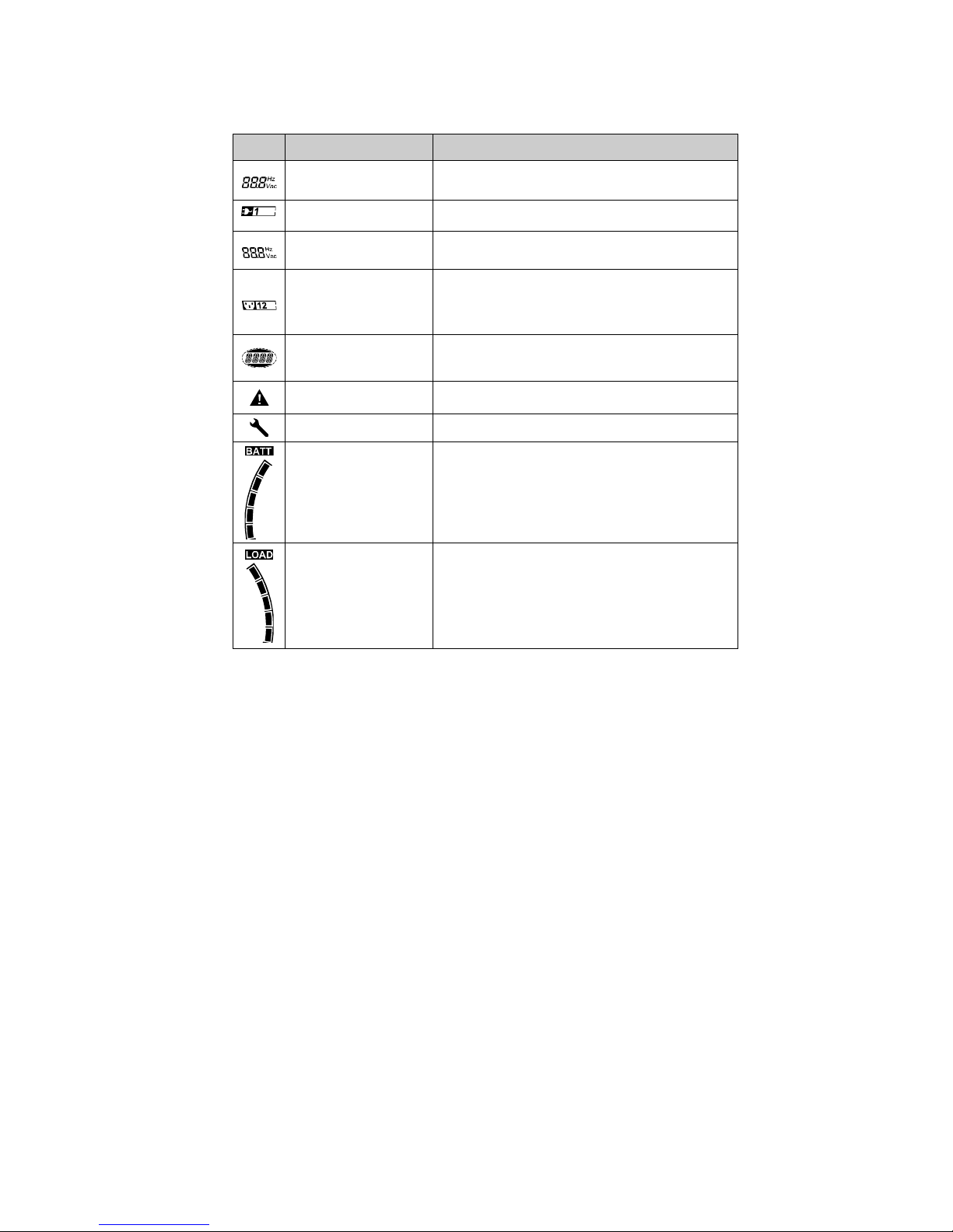
The following table describes the functions of the LCD display.
Table3. Description of LCD display function
No.
Description
Function
Input frequency and
voltage
Indicate the value of input frequency and voltage
Input plug indicator
Light on when the input power is at no loss.
Output frequency and
voltage
Indicate the value of output frequency and
voltage
Output plug indicator
The UPS has two groups of outlets. The
output plug indicator will light on if there is
output power respectively.
UPS status/user
setting display String
Strings Indicate the UPS status( see Table 4)
Strings Indicate user setting options( see Table
5)
Warning indication
Light on when the UPS is failure or alarm.
Settings
Light on when the UPS under settings mode.
Battery volume level
display
Indicate the amount of battery volume
remaining. Each battery volume level bar
indicates a 20% of total battery volume
Load capacity level
display
Indicate the percentage of UPS load capacity
which is being used by the protected
equipment. Each LCD level bar indicates a
20% of the total UPS output capacity.
This manual suits for next models
3
Table of contents
Popular UPS manuals by other brands


Eaton
Eaton 93PM IBC-L installation manual

CyberPower
CyberPower CP1350PFCLCD user manual

MGE UPS Systems
MGE UPS Systems PULSAR EVOLUTION 2200 Installation and user manual

inform
inform SAVER PLUS DSP SERIES user manual

Delta
Delta UPS602N2004N035 user manual

Eaton
Eaton 9PX 700 RT Installation and user manual


