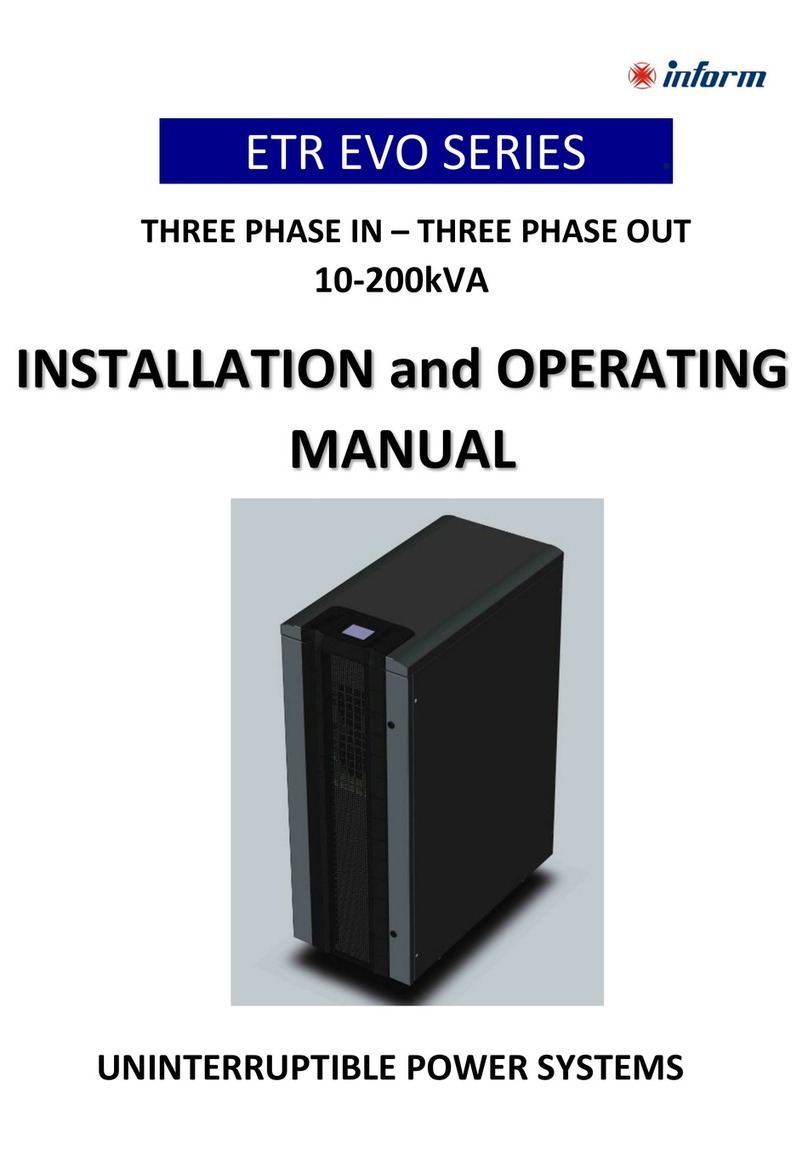
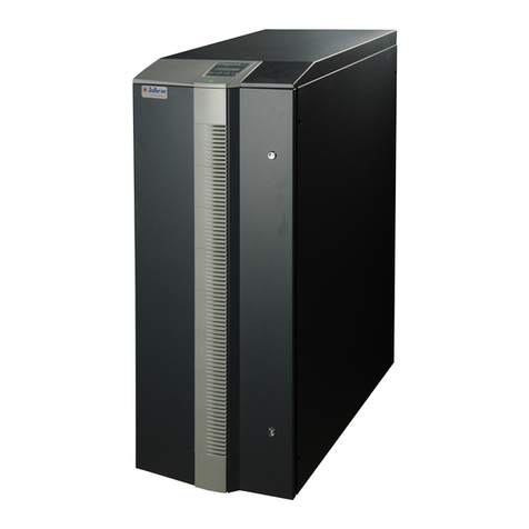
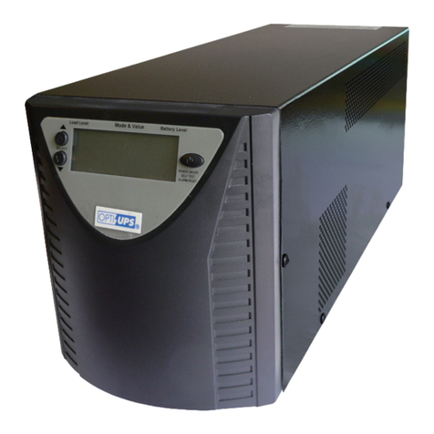
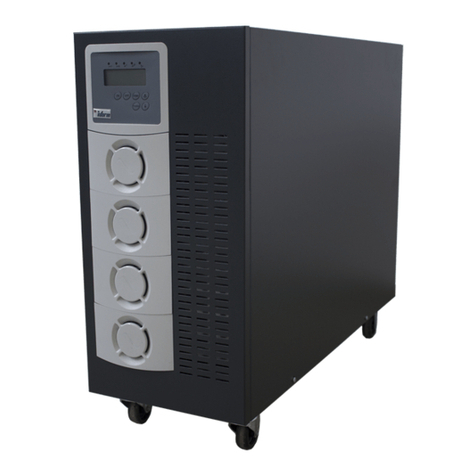
inform SAVER PLUS DSP SERIES User manual

288713580
SAVER PLUS DSP SERIES .
.
.
THREE PHASE IN – SINGLE PHASE OUT
15&20kVA
USER MANUAL
UNINTERRUPTIBLE POWER SUPPLY UPS


I
Important Notices
Thank you for choosing Inform UPS Systems. This document provides all the instructions necessary for
the installation and the operation of the Saver Plus DSP Uninterruptible Power Supply.
For the staff and the equipment safety, it is necessary for the users to fully read and understand this
manual before working on this equipment.
Please read the manual carefully, before working on this equipment!
Please keep the manual!
Description of the Symbols
IMPORTANT NOTICE! Please follow the instructions.
LIFE RISK! Please follow the instructions.
DANGER! Please follow the instructions otherwise the unit can be damaged or user can be hurt.

II
Contents
1Safety.......................................................................................................................................................... 1
2System Description....................................................................................................................................2
3Installation .................................................................................................................................................5
3.1 Handling ........................................................................................................................................................................ 5
3.2 Storage ........................................................................................................................................................................... 5
3.3 Positioning..................................................................................................................................................................... 6
3.4 Connections .................................................................................................................................................................. 6
3.4.1 Ground ( Earth ) Connection............................................................................................................................. 7
3.4.2 Input Connection................................................................................................................................................. 7
3.4.3 By-pass Input Connection .................................................................................................................................. 8
3.4.4 Battery Connection .............................................................................................................................................. 8
3.4.5 Output Connection............................................................................................................................................ 10
3.4.6 Communication Interface Connection............................................................................................................ 10
4Switch on and Switch off ..........................................................................................................................11
4.1 Switch on..................................................................................................................................................................... 11
4.2 Switch off .................................................................................................................................................................... 11
5Operating Instructions ............................................................................................................................ 12
5.1 Unit Operation ........................................................................................................................................................... 12
5.1.1 Operating Modes................................................................................................................................................ 12
5.1.1.1 On-line Mode (ONLINE)....................................................................................................................................12
5.1.1.2 By-pass Mode (BYPASS)......................................................................................................................................12
5.1.1.3 Battery Mode (BATTR) ........................................................................................................................................13
5.1.1.4 Shutdown (SHUTD) .............................................................................................................................................13
5.1.1.5 Inverter Failure (INVFLR)...................................................................................................................................14
5.1.1.6 Output Failure (OUTFLR)...................................................................................................................................14
5.1.1.7 Wait Mains (WTMNS) ..........................................................................................................................................14
5.1.2 Operating Types................................................................................................................................................. 14
5.1.2.1 Online Priority Operating (Normal Operation)................................................................................................14
5.1.2.2 By-pass Priority Operating (Green Mode).........................................................................................................15
5.1.2.3 UPS out of Function Operation..........................................................................................................................16
5.1.3 Operating Features and Values ........................................................................................................................ 17
5.1.3.1 Online Mode and Voltage Tolerance..................................................................................................................17
5.1.3.2 By-pass Mode Voltage Tolerance........................................................................................................................17
5.1.3.3 Battery Management and Autonomy Time........................................................................................................17
5.1.3.4 Temperature Management....................................................................................................................................19
5.1.3.5 Communication Interface.....................................................................................................................................19
5.1.4 Abnormal Conditions Operating Principles................................................................................................... 21
5.1.4.1 Overload..................................................................................................................................................................21
5.1.4.2 Output Short Circuit .............................................................................................................................................21
5.1.4.3 High Inrush Current Load at the Output...........................................................................................................22
5.2 Display ......................................................................................................................................................................... 22
5.2.1 Front Panel.......................................................................................................................................................... 22
5.2.1.1 Display (LCD) ........................................................................................................................................................23
5.2.1.2 LEDs........................................................................................................................................................................24
5.2.1.3 Buttons ....................................................................................................................................................................25
5.2.2 Alarms.................................................................................................................................................................. 25
6Important Operating Notices.................................................................................................................. 26
7Maintenance ............................................................................................................................................ 28
8Trouble Shooting ..................................................................................................................................... 29
9Technical Specifications (15kVA Saver Plus DSP UPS)......................................................................... 31
10 Technical Specifications ( 20kVA Saver Plus DSP UPS )....................................................................... 33

1
1Safety
For the staff and equipment safety, it is necessary for the users to fully read and
understand this manual before working on this equipment.
Avoid the sudden temperature changes, which can cause condensation inside the UPS. Otherwise,
wait for at least two hours before switching on.
UPS has to operate in an environment suggested in this manual. Please read chapter 3.3 ‘Positioning’.
Do not close ventilation holes or other openings.
Do not let enter any foreign materials inside the UPS.
Installation and commissioning have to be done by authorized technical service.
Earth (ground) connection has to be done.
Do not plug in and remove the communication interface cables during the lightning weather
conditions.
Avoid the risk of fire, all the connections have to be done by suggested cable dimensions. All cables
have to be isolated and properly installed.
Do not connect overload to the UPS output.
Do not open the UPS doors. There is high voltage risk.
Maintenance has to be done by authorized technical service.
In case of emergency (damage of the cabinet, front panel, or connections etc.) switch off the UPS, cut
off input voltage, and inform authorized technical service.
Please make the necessary packing if it is obligatory to move the UPS.

2
2System Description
On-line UPS connected between mains and load protects the load against voltage fluctuations, ripples, and
electricity cuts off.
Our UPS during the on-line operation provides stable pure sine wave. This pure sine wave is not affected
from the input voltage fluctuations. This helps to extend the life time of your sensible loads. Power factor
of the current consumed from the mains is nearly one. You do not have any problem on generator or
isolation transformer applications. Your reactive energy consumption decreases.
Over 80V mains voltage, smart battery charger charges the batteries. Batteries do not need any
maintenance.
In case of longer overload or inverter failure situation, UPS transfers the load to by-pass line, and load is
supplied from the by-pass input. When the normal conditions come back, UPS shall continue to supply
the load through inverter.
UPS control and management is done by digital signal processor ( DSP ) which is 200 times faster than
standard microprocessors. This helps to make your UPS smarter. DSP uses all the sources on optimum
conditions, observes the failure conditions, and communicates with your computer system.
UPS has standard communication interface. Using Inform software, you may protect your data and
operating Systems.
UPS block diagram is shown below.

3
Input and Output EMI filters
These filters prevent electromagnetic
interference between UPS, mains and loads.
Your UPS and loads are protected against high
voltage.
Input Thyristors
This helps to cut the energy flow between the
UPS input and boost rectifiers during the battery
mode or battery test.
Boost Rectifier
On mains operation, the boost rectifier adjusts
the mains voltage to the necessary DC voltage
level required for the inverter and helps to
provide sinus current with a power factor near
to 1 from the mains.
On battery mode it increases the battery voltage
level, required for the inverter and uses current
from the battery with a low ripple ratio thus
extending the battery life.
Inverter
The inverter helps to obtain a very constant AC
voltage level at the output by using DC voltage
at the boost rectifier’s output.
Inverter Thyristors
This helps to separate inverter from the output
electronically in case of by pass mode operation
or UPS output off conditions.
By-pass Thyristors
This helps to separate by-pass input from the
UPS output electronically.
Battery Thyristors
This helps to separate battery from the boost
rectifier electronically.
Battery
The necassary energy supply is obtained from
the batteries whenever the input mains supply is
not sufficient for the supply of the loads.
By-pass Switch
It is a mechanical switch which connects the ups
output to the bypass input and provides
uninterruptible transfer. It is generally used to
isolate the ups without disconnecting the load
from output and the mains from input.
By-pass Input
In some cases, it is requested to supply by pass
line from another mains or sources. In this
application, it is used split by-pass. (Please
inform your contact about your need)
Your UPS features:
Feature
Benefit
IGBT Technology
Transformerless design Compact design, small dimensions and low weight
DSP (digital signal processor)
technology
DSP is 200 times faster than standard microprocessors. This provides;
To use all the sources in optimum level
To observe carefully the failure conditions
PFC technology
High input power factor. This helps;
To consume low reactive power
Not to load the installation extra (cables, transformers, generators)
Clean power for the mains
Wide input voltage tolerance
(on-line operation even the mains is
between 80 – 280 V)
This helps to reduce battery usage and guarantee battery to be fully
charged and extend the battery life time.
On-line double conversion
technology
UPS output voltage is sine wave same as ideal mains source. UPS output
total harmonic distortion is very low.

4
Feature
Benefit
On-line and battery modes
operation against inrush current
Some loads when they are switched on, consumes high inrush current.
On such cases normal UPS switches off, or passes to by pass.
Our UPS behaves like a current source. (In case of high inrush current
consumption, UPS adjust the output voltage and fix the current value.)
Load is not affected the from inrush current.
On-line and battery modes
operations in short circuit
conditions
In case of a short circuit at output, UPS behaves like current source, (In
case of high current consumption, UPS adjust the output voltage and fix
the current value), and trigger the fuse between UPS and load. So short
circuit condition is over, and other loads are not affected.
Normal UPSs switch off in such cases.
Info (smart) Battery Management
Thanks to algorithms used in battery charging, battery lifetime is
extended. This helps:
To continue charging the battery even the mains input go down to
80V.
Load independent charging voltage.
Temperature controlled battery charging
Additionally;
Battery autonomy time is calculated, thanks to artificial intelligent
algorithms.
Current ripple is minimum level during the discharge.
Battery testing is available.
Temperature Management
UPS measures the temperature of different internal parts, and
calculates semi-conductor junctions’ temperature. This helps;
To calculate overloading time in a reliable way.
To protect against over temperature.
Overload Time Management
UPS continues its online operation for a certain period during overload
condition. This depends on overload percentage, and temperature of
semi conductors. Calculation is done as follows;
Load is supplied for a certain period by UPS, considering output
fuse temperature characteristics, and if by-pass input voltage is
available, and then pass to by-pass.
Meanwhile, if junction temperature passes the critical level, if by-
pass input voltage is available, then passes to by pass.
Non-moving parts except the fans
Maintenance free lead acid battery
usage
Less maintenance need
Communication interface Using Inform software, you can protect your data and operating
Systems.
Output voltage is not affected by changes on the mains input and load level.
High efficiency (Low power consumption)
Uninterruptible Manual Bypass Feature

5
3Installation
Check if the UPS has been subjected to any damage before unpacking it.
If you notice any damage, please contact to transport firm. Check if all the additional parts have
been supplied with the UPS.
Please make sure that the packing contains the following;
UPS
User Manual
Test Reports
Before the installation, please check if your UPS is customized following your special
requirements (if any).
In standard UPS, output voltage and frequency are adjusted to 220 V/50 Hz.
3.1 Handling
UPS and battery weights are given in the chapter 9. You may calculate the total weight.
If needed to move the UPS, it is obligatory to pack the unit. It is suggested to keep the original
packing.
3.2 Storage
Please store the UPS and batteries in an environment where the temperature is between –15 °C +55 °C,
no receipt of direct sunlight, far from the heating, in a dry place.
Environmental humidity must be between 20% 95% (none condensing).
If the batteries will be stored more than 3 months, it is suggested to charge the batteries periodically.
Relation between storage temperature and period is shown below;
Storage temperature below 20 °C’, once per 9 months
Storage temperature between 20 °C and 30 °C, once per 6 months,
Storage temperature between 30 °C and 40 °C, once per 3 months,
Storage temperature above 40 °C’, once per 2 months
Please follow up the instructions of “installation” chapter for earth, input, and battery connections. Please
turn to ‘ I ’ position UPS’s battery and input fuses and also additional battery cabinet fuses if present.
Please charge the batteries at least 12 hours.

6
3.3 Positioning
UPS and battery cabinet (if any) have to be positioned in an environment;
•No direct sun access,
•Dry,
•Far from the heating equipments
•Well-ventilated.
•No excessive dust
In order to maintain adequate ventilation of UPSs and battery cabinet, ensure the air vents are not blocked
and leave at least 20cm space at the rear side of the unit for ventilation.
Even though the operating temperature of the UPS and batteries are between 0-40 °C, It is suggested to
provide an environment temperature between 20-25 °C to get maximum performance from the UPS and
batteries.
Environmental humidity must be between 20% 80% (none condensing).
3.4 Connections
Connections must be done by authorized technical service staff. Life risk for user!
Temperature changes such as from cold to hot environment may cause condensation. It is
dangerous to operate the UPS. Please wait at least two hours before making the connections.
Connection terminals are in the front side of the UPS.
Standard UPS fuses and connectors settlements are shown below;

7
Units with internal batteries have hazardous voltages on the battery connectors even if the battery
circuit breaker is in “0” position. Do not touch the battery connectors.
Units with internal batteries can produce output voltage even if no connection is made.
Therefore, it is mandatory to keep all circuit breakers in “0” position and not to push the buttons
on the front panel during installation.
Please follow the instructions as explained below.
3.4.1 Ground ( Earth ) Connection
UPS ground (earth) connections have to be done.
UPS input ground (earth) connector has to be connected to (low resistive) ground (earth) line.
Load ground (earth) connections have to be done through UPS output ground connector.
If any battery cabinet exists, grounding has to be done through battery ground (earth) connector.
Minimum cable crossections are given in the chapter 9.
3.4.2 Input Connection
Please add 4 poles miniature circuit breaker to distribution box where to UPS is to be connected. Please
do not forget to add leakage current relay.
It is suggested to add to a miniature circuit breaker that fits UPS input fuse value. The value&type of the
fuses are stated in the technical specifications section.
Leakage protection relay value must be the total value of 30mA (UPS input leakage current relay) and total
leakage current value of the load connected to UPS. Relay must be protected type against peak current
that can be happened on EMI filter capacitor.
Above informations are given for the supply of UPS only. If more equipment will be supplied, please
make the calculation accordingly.
Changes on distribution panel have to be done by authorized persons only.
After the necessary changes, switch on ‘ 0 ‘ position the automatic fuse on the distribution box, and
connect the phases to R, S, T clemenses through the automatic fuse on the panel, and neutral to N
connection.
Before connecting the input cables, switch on ‘ 0 ‘ position the automatic fuse on the distribution
box.
Cables to be used for UPS and distribution box connections are shown in the chapter 9. Risk of
fire!
IEC 62040-3 (EN 50091-3) standard, suggests to put below sticker next to automat that UPS to
be connected in the distribution box against the risk of leakage reverse voltage. Otherwise can
cause life risk!

8
Isolate uninterruptible power supply before working on this circuit.
3.4.3 By-pass Input Connection
Please follow up the below instructions for the by-pass line connection;
Please add two poles automatic fuse to distribution box where to UPS is to be connected. Please do not
forget to add leakage current relay.
Fuse value&type is stated in the technical specifications section of the user manual.
Leakage protection relay value must be the total value of 30mA (UPS input leakage current relay) and total
leakage current value of the load connected to UPS. Relay must be protected type against peak current
that can be happened on EMI filter capacitor.
Above informations are given for the supply of UPS only. If more equipment will be supplied, please
make the calculations accordingly.
Changes on distribution box have to be done by authorized persons only.
After the necessary changes, switch on ‘ 0 ‘ position the automatic fuse on the distribution box, and
connect the phase to by-pass phase Clemens (BYP) through the automatic fuse, and neutral to N1
clemens.
Before making by-pass connection, switch on ‘ 0 ‘ position the automatic fuse on the distribution
box.
3.4.4 Battery Connection
If the batteries are installed inside the UPS cabinet, there is no need to make battery connections.
If the batteries shall be put in a separate additional battery cabinet or make parallel to the batteries inside
the UPS, please follow up the instructions below;
Switch on to “0” position the battery cabinet fuse.
Connect the B- on the battery cabinet to B- on the UPS
Connect the B+ on the battery cabinet to B+ on the UPS,
Connect the N3 on the battery cabinet to N3 on the UPS,
Connect the PE on the battery cabinet to battery ground (earth) on the UPS.
Locate the battery fuses to their location sockets.
In order to obtain better performance from the battery, please charge at least 10 hours before the
operation.

9
You may do the initial charge of the batteries after the connection of the loads. But during the initial
charge, if the UPS transfers the loads to the output, then the charge wouldn’t be completed. In order to
prevent this, the loads shouldn’t be supplied through UPS all along the initial charge time. Please follow
up the below procedure;
In order to make the initial charge after connecting the loads to the output;
•Perform the output connections as in the explained section,
•Turn the by-pass switch in to “I” (by-pass) position on the UPS,
•Turn the UPS battery fuse and external battery cabinet fuse( if present ) in “I” position,
•Turn the automatic fuses on the distributions panel that the UPS is connected to mains and
by-pass in “I” position,
•Turn the input, by-pass and battery charger fuses of the UPS in “I” position,
•Turn the output fuse of the UPS in “I” position,
•Turn the fuses between the UPS and the loads in “I” position.
The loads are started to be supplied through manual bypass switch. 10 seconds after the UPS is energized,
you start to observe “BYPASS OK G” or “SHUTD. OK” on the top line of the front panel. On the
bottom line “MB” message is still continued to be observed.
The loads cannot be protected from the outgates and disturbances during the initial charge
period due to they have been transferred to by-pass input.
If the mains cut off during the initial charge, the charge time should be prolonged as much as
the cut off time.
At the end of the advised charge time, before switching on the UPS, the following items should be
performed;
•Switch off the loads,
•Turn the input and by-pass fuses of the UPS in “0” position,
•Turn the battery fuse of the UPS and external battery cabinet fuse (if present) in “0” position,
•Turn the manual by-pass switch in “0” position.
Now you can switch on the UPS safely.
In order to make the initial charge before connecting the loads to the output;
•Turn the external battery cabinet fuse (if present) in “I” position,
•Turn the battery fuse on the UPS in “I” position,
•Turn the automatic fuse on the mains distribution panel, where the UPS is connected, in “I”
position,
•Turn the UPS input and battery charger fuse in “I” position.
If the mains cut off during the initial charge, the charge time should be prolonged as much as the
cut off time.

10
Do not touch any clemens on the unit during the operation. For your own safety, please make the
output connections after the end of charging process according to the explanations in the related
section.
At the end of the advised charge time, before making the output connections, the following items should
be performed;
•Turn the UPS input fuse in “0” position,
•Turn the battery fuse and external battery cabinet fuse (if present) in “0” position,
•Turn the automatic fuse on the mains distribution panel, where the UPS is connected, in “0”
position.
•Please check and control that the manual bypass switch is in “0” position.
Now you can make the output connections safely.
3.4.5 Output Connection
It is suggested to use different fuse and leakage current relay for each independent load. In case of
short circuit, related fuse will be triggered and remaining loads shall continue to be supplied.
Nominal current value of the fuse between load and UPS must be lower than the fault clearing
current value given in the ‘ Technical Specifications ‘ chapter. Otherwise, fuse shall not be
triggered before 10ms, and load energy shall be interrupted.
Before making output connections, switch on to ‘ 0 ‘ position the automatic fuse on the
distribution box, UPS input, output, battery, and by pass (if any), additional battery cabinet( if
any) automats.
Load will be connected L2, N2, and ground (earth) connections at the rear side of the UPS.
Cables dimensions between UPS and loads have to be chosen following load current.
Load power connected at the UPS output, must be not bigger then UPS nominal power.
3.4.6 Communication Interface Connection
Please contact to authorized Inform distributor to get the optional accessories such as SNMP adapter,
modem, remote control panel, software, ..etc. Information about this section is given in the
“communication interface” section.

11
4Switch on and Switch off
4.1 Switch on
After making all the connections mentioned in the chapter 3, you need to switch on to ‘ I ‘ position the
automatic fuse on the distribution box, UPS input, output, battery, and by pass automats (If there is any
external battery cabinet, then turn its fuse in “I". If mains voltage is within the limits, the unit switches on.
UPS makes self-test for few seconds to check if everything is normal, and then starts to supply the load.
If you want to switch on the UPS when the mains is out of the limits, please press ‘ CS ‘ button.
4.2 Switch off
To switch off the UPS, please press “0” button. Then the load is transferred to by pass. If the mains is out
of the limits, UPS pass to shut down mode.
To stop the load to be supplied, please turn the UPS output fuse to “0” position.
To switch off the UPS, please turn all the fuses to “0” position.
Even though all the fuses are in “0” position, there is still energy on the connections. Do not
touch.
If any work will be done on UPS clemenses, fuses on mains, by pass distribution box, battery
cabinet (if any), must be turned to “0” position.
Devices with internal batteries have hazardous voltages on battery connectors even if the
battery circuit breaker is in “0” position. Do not touch these connectors.

12
5Operating Instructions
5.1 Unit Operation
5.1.1 Operating Modes
Following the status of mains&by-pass voltage, UPS can operate either one of the below operating modes.
5.1.1.1
On-line Mode (ONLINE)
Online mode is available if the mains is within the allowed operating limits. In this mode, UPS supply the
load and charge the batteries. Load is supplied through inverter and inverter is on-line.
If;
On-line mode is chosen, the mains input is in the acceptable limits, and there are no abnormal
conditions ( such as over temperature, overload, failure ..etc),
Green mode is chosen, by pass input voltage is out of limits, but the mains input voltage is in the
acceptable limits, and there are no abnormal conditions (such as over temperature, overload, failure
..etc),
UPS operates in on-line mode.
5.1.1.2
By-pass Mode (BYPASS)
If the voltage in the by-pass input is transferred to the output by using either electronic or manual switch,
this mode is called by-pass mode. Your UPS has both electronic (static) and manual switch.
You can pass to Maintenance Bypass Mode by using the manual bypass switch on the ups. This switch is
used to transfer the bypass voltage to the output of the ups manually when the ups is not in function.
Maintenance Bypass Switch (manuel bypass) is an uninterruptible switch. In case of use, the
instructions in section 5.1.2.3 should be followed up properly in order to maintain an
uninterruptible transfer to byapss. In condition to transfer from manual bypass line to normal
operations, the instructions in 5.1.2.3 should be followed up.
On by-pass mode, by pass input voltage is transferred to output through the thyristors. Load is supplied
by by-pass input voltage. Inverter is off.
By-pass input voltage must be within the operating limits.
The unit;
•Stays at this mode when green mode is chosen, if by pass input voltage is within the
acceptable limits,
•On-line mode is chosen, by-pass input voltage is within the acceptable limits, if one of the
below conditions occur, UPS passes to by-pass mode. If normal conditions are obtained, then
UPS passes to on-line mode;
*Prolonged overloading,
*Over temperature,
*Failure on the UPS,
During the on-line operation, if the by-pass input voltage is within acceptable limits, or in green mode
operation, when you push to“0” button, UPS passes to by-pass mode. If the by-pass input voltage is
out of limits, UPS does not pass to battery mode, and switch off itself.

13
If the UPS is transferred to by pass mode by pushing “0” button, in case by-pass input voltage is
out of the limits, UPS passes to shutdown mode or switch off, depending on mains voltage. It is
suggested to use green mode if you don’t want any interruption.
If the by-pass input voltage gets out of limits after the “0” button is pressed during on-line operation, UPS
shall switch into Shutdown Mode.
If UPS passes to by-pass mode because of overload conditions, and by-pass input voltage gets out of the
limits, it is dependent on the amount of load for the ups to return to online operation.
5.1.1.3
Battery Mode (BATTR)
In this mode of operation, UPS converts the battery voltage to a suitable DC voltage, which can be
converted to a voltage value equal to mains voltage of the inverter. UPS is at the same time on by-pass
mode. This is an exceptional case that UPS is on two modes at the same time.
During on-line mode, and mains input is out of the limits, UPS passes to battery mode. (If there are
no other abnormal conditions). Necessary energy to operate the inverter is supplied by the battery.
During green mode, both mains input and by-pass input are out of the limits, UPS passes to battery
mode. Necessary energy to operate the inverter is supplied by the batteries.
During green mode, mains input only is out of the limits, inverter is supplied from battery, but load is
supplied from the by-pass line.
You may switch on the UPS by pushing “CS” button, even if mains input is lower than 130 V or input
fuse is on “0” position. In this case UPS switch on shutdown mode, and make self test. If everything is ok,
UPS operate on battery mode.
Autonomy time depends on battery type, quantity, and load level. UPS stops feeding the loads if the
battery voltage falls under a certain value. Battery life decreases if battery capacity falls below a certain
level. Therefore, UPS stops operating in battery mode when the battery capacity falls below 30% of its
total capacity.
5.1.1.4
Shutdown (SHUTD)
During the shutdown mode, even the UPS is switched on, there is no energy on the output and load is not
supplied.
UPS makes self-test during the start up to check if everything is normal. During this operation, UPS is on
shutdown mode.
Other shutdown mode conditions;
User push the “0” button when the by-pass input is out of the limits,
UPS switches into shutdown mode if by-pass input voltage gets beyond limits, while mains voltage is
within limits and UPS is disabled,
User push the “0” button, and send shut down command through communication interface.
In addition,
During the battery mode, if shut down command is sent through the communication interface, and if
the mains comes back to normal conditions, for a short period UPS passes to shutdown mode, and
then passes to normal ( mode chosen by the user, on line, green or by pass mode) operating mode.
During the on-line or green mode operation, if shut down command is sent through communication
interface, for a short period, UPS passes to shutdown mode, and then passes to normal ( mode
chosen by the user, on line, green or by pass mode) operating mode.

14
If “0” button is pushed during the start up self-test, even the test is successful, UPS stays at this mode.
In order to pass on-line mode, you need to push “I” button once.
5.1.1.5
Inverter Failure (INVFLR)
If there is a failure, UPS pass to INVFLR mode. If failure happens during the on-line operation, UPS
passes to by-pass mode. If by-pass input is not available, it gives OUTFLR.
When you see the UPS in INVFLR operation, take out the load, and try to start up the unit
maximum two times. If it does not work, please contact to technical service.
5.1.1.6
Output Failure (OUTFLR)
If there is any possibility to damage the loads, UPS passes to OUTFLR mode. UPS shuts down the
output, and loads are not supplied.
During the OUTFLR operation, UPS is not switched off; there is no output voltage only.
Possible reasons are listed below;
During the on-line operation, short circuit happens at the output and continues more than 100 ms,
Due to conditions, UPS try to pass to b-pass mode, but the by-pass input voltage is not within the
acceptable limits,
During the INVFLR operation, UPS try to pass to by pass mode, but does not succeed.
When the UPS is on OUTFLR operation, “0” sign appears on the right side of the display.
If OUTFLR conditions are finished, if you push twice to “I” button, UPS starts to its normal operation.
Before to start the normal operation, please check the fans on the rear side. If the fans are not
working, please contact to technical service.
Do not open the case or put any object in the holes to check if the fans are working.
5.1.1.7
Wait Mains (WTMNS)
Wait mains, means that UPS cuts off the output voltage until the mains input comes to allowed limits.
When the mains input reaches to acceptable limits, UPS passes to on-line mode.
In order to start WTMNS operation, you need to send the shutdown command through communication
interface during the battery mode. At the end of time given by the user, UPS pass to WTMNS operation.
If shutdown command is sent during the on-line or green mode, at the end of defined time, UPS passes to
shutdown mode and then returns to the operation mode defined by the selected operating type.
During the WTMNS operation, if you want to switch on the UPS manually. Please press first to“0”
button, and switch off, and push to “CS” button. UPS starts on battery mode.
5.1.2 Operating Types
5.1.2.1
Online Priority Operating (Normal Operation)
When you turn the input fuse to “I” position, if the mains voltage is over 130V, UPS is switched on, and
after the test if everything is normal and if the “0” and “I” buttons were not pressed during the test, UPS
starts in this operation type.

15
The same is true if the UPS has been started up by pressing CS button in case of a mains interruption.
If the mains input is out of the tolerance, UPS passes to battery mode. When the mains input returns to
normal conditions, UPS passes automatically to on-line operation.
Even though the mains input is within the operating limits, but there are abnormal conditions (such as
over temperature, continuous overload, failure etc), UPS passes to by-pass operation if the by-pass input is
within the operating limits. If the by-pass input is out of the tolerance, the unit either passes to shutdown
mode or switch off. If the unit passes to by-pass mode, when the abnormal condition is over, UPS starts
to online operation.
You will see on the right top of the screen as ‘ N ’ sign indication during the normal operation.
Normal Operation is the safest operating type. Load is fully protected on normal operation only.
To pass to green mode operation from the normal operation, please push the “I” button;
Two times if there is audible alarm,
One time if there is no audible alarm.
To pass to UPS out of function operation, please push the “O” button.
5.1.2.2
By-pass Priority Operating (Green Mode)
UPS operates on by-pass mode if the by-pass input is within the operating limits. If the by-pass input is
out of the limits, UPS check if the mains input available for on-line operation, then pass to on-line
operation. When the by-pass input turns to its normal conditions, it passes to by-pass mode.
If the by-pass and mains input are not available or out of limits, UPS passes to battery mode. Which ever
comes to its normal conditions first, UPS passes that operation mode.
On green mode, inverter is off, and efficiency is very high. This provide energy saving.
It is suggested to use normal operation. During the green mode, load is not fully protected against
output short circuits, and disturbances.
You will see on the right top of the screen as ‘ G ’ sign indication during the green mode operation.
To pass to on-line mode operation from the green mode operation, please push the “I” button;
Two times if there is an audible alarm,
One time if there is no audible alarm.
To pass to UPS out of function operation, please push the “O” button.

16
5.1.2.3
UPS out of Function Operation
transfer from online operation to manual bypass
Please proceed as described below in order to transfer the load from online operation to manual bypass
operation without interruption. The below instructions should be followed up respectively for user safety
and preventing the load to be disenergized .
•please check that UPS is at online operation mode ( On the front display panel of the ups, “
ONLINE OK” message should be observed. )
•Pressing the “ I “ button on the front panel of the ups for necessary times, provide the transfer to
GREEN MODE . ( On the right upper line of the display panel, “G” letter should be observed. )
•On the front display panel “ BYPASS OK” message should be observed and the bypass LED
should lit.
•Bring the Manual Bypass Switch to “1” position.
•Please check and observe the “MB” message on the lower line of the front display panel.
•Bring the output, bypass, battery charger and battery fuses to “0” position .
•Please check and control that the UPS is switched off completely.
Now the connected loads are supplied through the manual bypass switch of the ups from bypass line. In
case of a energy cut off during this operation mode, your connected
loads shall remain without energy.
CAUTION:
Although the fuses of the UPS is at “0” position and the UPS is switched off, if the manual bypass
switch is at “1” position than there is still bypass voltage on the output Clemens of the ups and on the
supply part of the loads. Do not operate on these points ( output Clemens and load supply parts)
before taking the manual bypass switch to “0” position.
Check the user manual in case of non-described conditions in this instruction sheet.
Exceptional Cases
If you can not transfer your UPS to static bypass by pressing “I” button before passing to manual bypass
and observe “ ONLINE OK G” message on the front panel, this is an indication of the unavailibility of
the bypass voltage for transfer. This means that the bypass voltage and/or frequency is out of allowed
limits. Please check and control that you have the bypass connection and bypass fuse is in “1” position.
until you observe “G” message on the front panel, please pres continously to “I” button. If you bring the
manual bypass switch in “1” position although you have not received the “BYPASS OK” message on the
front panel, then you energise the loads with an inconvenient voltage and/or frequency. During this
transfer even your loads may remain without energy for a while. If you observe “BATTR. OK” message
on the front panel, then this means that the ups is operating from the mains due to the lack of input
mains. If the input fuse is not in “0” position and there is bypass voltage, then by pressing “I” button
from the front panel, you can obtain the transfer to green mode operation. If you observe “BYPASS OK”
message on the front panel, then by bringing the manual bypass switch to “1” position, you can provide
the uninterruptible transfer to manual bypass line.
Table of contents
Other inform UPS manuals
inform
inform Pyramid Plus Specification sheet
inform
inform DSP User manual
inform
inform InfoSTS User manual
inform
inform Informer 1000VA User manual
inform
inform GUARDIAN User manual
inform
inform PYRAMID DSP PREMIUM Series User manual
inform
inform 500 User manual
inform
inform PDSP31010 User manual
inform
inform DSP FLEXIPOWER SERIES User manual
inform
inform Guard 500VA User manual
