Chuphotic VENUS Ultimate S2.2 1KVA S User manual
User Manual
True Online Double Conversion UPS
VENUS Ultimate S2.2 VNU1-3KVA

All rights reserved.
The information in this document is subject to change without notice.
Publish statement
Thank you for purchasing this series UPS.
This series UPS is an intelligent, single phase in single phase out, high frequency
online UPS designed by our R&D team who is with years of designing experiences
on UPS. With excellent electrical performance, perfect intelligent monitoring and
network functions, smart appearance, complying with EMC and safety standards,
The UPS meets the world’s advanced level.
Read this manual carefully before installation
This manual provides technical support to the operator of the equipment.

2
Table of Contents
1.Important Safety Warning..................................................................................................................3
1-1Transportation ............................................................................................................................3
1-2Preparation...................................................................................................................................3
1-3Installation....................................................................................................................................3
1-4Operation......................................................................................................................................4
1-5Maintenance, service and faults...........................................................................................4
1-6Symbols used in this guide.....................................................................................................5
2.Installation and setup...........................................................................................................................5
2-1Unpack checking ........................................................................................................................5
2-2Real panel view ...........................................................................................................................6
2-3Setup the UPS..............................................................................................................................7
2-4UPS start up and turn off........................................................................................................8
3.Operations..............................................................................................................................................12
3-1Button operation......................................................................................................................12
3-2LCD display .................................................................................................................................13
3-3UPS setting.................................................................................................................................15
3-4Operational Status and Mode(s) ........................................................................................17
3-5Alarm or Fault reference code.............................................................................................18
4.Troubleshooting ...................................................................................................................................19
5.Storage and Maintenance.................................................................................................................21
6.Options ....................................................................................................................................................21
7.Specification ..........................................................................................................................................24

3
1. Important Safety Warning
Important safety instructions – Save these instructions
Please comply with all warnings and operating instructions in this manual strictly.
Save this manual properly and read carefully the following instructions before
installing the unit. Do not operate this unit before reading through all safety
information and operating instructions carefully
There exists dangerous voltage and high temperature inside the UPS. During the
installation, operation and maintenance, please abide the local safety instructions
and relative laws, otherwise it will result in personnel injury or equipment damage.
Safety instructions in this manual act as a supplementary for the local safety
instructions. Our company will not assume the liability that caused by
disobeyingsafety instructions.
1-1 Transportation
Please transport the UPS system only in the original package to protect against
shock and impact.
1-2 Preparation
Condensation may occur if the UPS system is moved directly from cold to warm
environment. The UPS system must be absolutely dry before being installed.
Please allow at least two hours for the UPS system to acclimate the environment.
Do not install the UPS system near water or in moist environments.
Do not install the UPS system where it would be exposed to direct sunlight or
near heater.
Do not block ventilation holes in the UPS housing.
1-3 Installation
Do not connect appliances or devices which would overload the UPS system (e.g.
laser printers) to the UPS output sockets.
Place cables in such a way that no one can step on or trip over them.
Do not connect domestic appliances such as hair dryers to UPS output sockets.
The UPS can be operated by any individuals with no previous experience.
Connect the UPS system only to an earthed shockproof outlet which must be
easily accessible and close to the UPS system.
Please use only VDE-tested, CE-marked mains cable (e.g. the mains cable of your
computer) to connect the UPS system to the building wiring outlet (shockproof
outlet).
Please use only VDE-tested, CE-marked power cables to connect the loads to the
UPS system.

4
When installing the equipment, it should ensure that the sum of the leakage
current of the UPS and the connected devices does not exceed 3.5mA.
1-4 Operation
Do not disconnect the mains cable on the UPS system or the building wiring
outlet (shockproof socket outlet) during operations since this would cancel the
protective earthing of the UPS system and of all connected loads.
The UPS system features its own, internal current source (batteries). The UPS
output sockets or output terminals block may be electrically live even if the UPS
system is not connected to the building wiring outlet.
In order to fully disconnect the UPS system, first press the OFF/Enter button to
disconnect the mains.
Prevent no fluids or other foreign objects from inside of the UPS system.
1-5 Maintenance, service and faults
The UPS system operates with hazardous voltages. Repairs may be carried out
only by qualified maintenance personnel.
Caution - risk of electric shock. Even after the unit is disconnected from the
mains (building wiring outlet), components inside the UPS system are still
connected to the battery and electrically live and dangerous.
Before carrying out any kind of service and/or maintenance, disconnect the
batteries and verify that no current is present and no hazardous voltage exists in
the terminals of high capability capacitor such as BUS-capacitors.
Only persons are adequately familiar with batteries and with the required
precautionary measures may replace batteries and supervise operations.
Unauthorized persons must be kept well away from the batteries.
Caution - risk of electric shock. The battery circuit is not isolated from the input
voltage. Hazardous voltages may occur between the battery terminals and the
ground. Before touching, please verify that no voltage is present!
Batteries may cause electric shock and have a high short-circuit current. Please
take the precautionary measures specified below and any other measures
necessary when working with batteries:
-remove wristwatches, rings and other metal objects
-use only tools with insulated grips and handles.
When changing batteries, install the same number and same type of batteries.
Do not attempt to dispose of batteries by burning them. This could cause battery
explosion.
Do not open or destroy batteries. Escaping electrolyte can cause injury to the skin
and eyes. It may be toxic.

5
Please replace the fuse only with the same type and amperage in order to avoid
fire hazards.
Do not dismantle the UPS system.
1-6 Symbols used in this guide
WARNING!
Riskofelectricshock
CAUTION!
Readthisinformationtoavoidequipmentdamage
2. Installationand setup
NOTE: Before installation, please inspect the unit. Be sure that nothing inside the
package is damaged. Please keep the original package in a safe place for future use.
2-1 Unpack checking
Don’t lean the UPS when moving it out from the packaging.
Check the appearance to see if the UPS is damaged or not during the
transportation, do not switch on the UPS if any damage found. Please contact the
dealer right away.
Check the accessories according to the packing list and contact the dealer in case
of missing parts.
It includes:
(1) UPS user's guide
(2) Software Suite CD
(3) USB cable
(4) Power cord (Input and output)
(5) RS232 cable
6
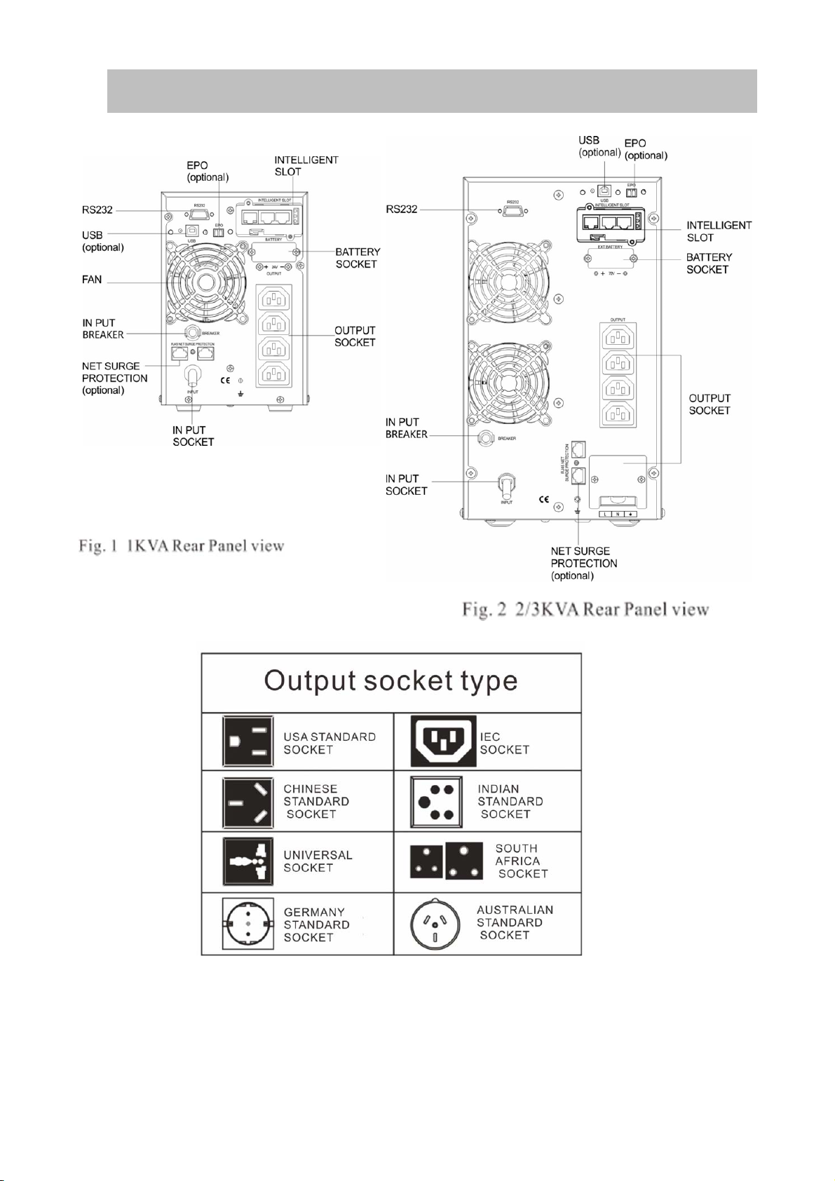
2-2 Real panel view

7
2-3 Setup the UPS
Step 1: UPS input connection
Plug the UPS into a two-pole, three-wire, grounded receptacle only. Avoid using extension
cords.
For 208/220/230/240VAC models: The power cord is supplied in the UPS package.
Step 2: UPS output connection
For socket-type outputs, simply connect devices to the outlets.
For terminal-type input or outputs, please follow below steps for the wiring
configuration:
a) Remove the small cover of the terminal block
b) Suggest using AWG14 or 2.1mm
2
power cords for 3KVA (200/208/220/230/240VAC
models).
c) Upon completion of the wiring configuration, please check whether the wires are
securely affixed.
d) Put the small cover back to the rear panel.
Step 3 Communication connection
Communication port:
To allow for unattended UPS shutdown/start-up and status monitoring, connect the
communication cable one end to the USB/RS-232 port and the other to the
communication port of your PC. With the monitoring software installed, you can
schedule UPS shutdown/start-up and monitor UPS status through PC.
The UPS is equipped with intelligent slot perfect for either SNMP or Relay card. When
installing either SNMP or Relay card in the UPS, it will provide advanced communication
and monitoring options.
NOTE: USB port and RS-232 port can’t work at the same time.
Step 4: Turn on the UPS
Press the ON button on the front panel for two seconds to power on the UPS.
Note: The battery charges fully during the first five hours of normal operation. Do not
expect full battery run capability during this initial charge period.
Step 5: Install software
For optimal computer system protection, install UPS monitoring software to fully
configure UPS shutdown. You may insert provided CD into CD-ROM to install the
monitoring software.
Step 6: External battery connection
If your UPS is not including batteries. Please connect external batteries as below chart.

8
2-4 UPSstartup and turn off
Startup operation
(1) Turn on the UPS in line mode
NOTE Verify that the total equipment ratings do not exceed the UPS
capacity to prevent an overload alarm.
a) Once mains power is plugged in, the UPS will charge the battery, at the moment,
the LCD shows that the output voltage is 220, which means the UPS automatic ally
tart the inverter. If it is expected to change to bypassmodel, you can Press “OFF”
key.
b) Press and hold the ON key for more than
three
seconds to start the UPS, then it will
start the inverter.
c) Once started, the UPS will perform a self-test function, LED will light and go out
circularly and orderly. When the self-test finishes, it will come to line mode, the
corresponding LED lights, the UPS is working in line mode.
(2) Turn on the UPS by DC without mains power
a) When mains power is disconnected, press and hold the ON key for more than half a
second to start UPS.
b) The operation of the UPS in the process of start is almost the same as that when
mains power is in. After finishing the self-test, the corresponding LED lights and the
UPS is working in battery mode.
Turn off operation
(1) Turn off the UPS in line mode

9
a) Press and hold the OFF key for more than half a second to turn off the UPS and
inverter.
b) After the UPS shutdown, the LEDs go out and there is no output. If output is
needed, you can set bps “ON” onthe LCD setting menu.
(1) Turn off the UPS by DC without mains power
a) Press and hold the OFF key for more than half a second to turn off the UPS.
b) When turning off the UPS, it will do self-testing firstly. The LEDs light and go out
circularly and orderly until there is no display on the cover.
Operation and Display Panel
The operation and display panel, shown in below chart, is on the front panel of the
inverter. It includes three indicators, four function keys and a LCD display, indicating the
operating status and input/output power information.
LCD control panel introduction
(1)LED(fromright to left: “alarm”, “bypass”, “battery”, “inverter”);
(2)On-Line UPS LCD display;(3)Function keys
LED Indicator
Indicator Description
Red
OnThe UPS has an active alarm or fault.

10
Yellow
The UPS is in Bypass mode.
OnThe UPS is operating normally
onbypassduring High Efficiency operation.
Yellow
OnThe UPS is in Battery mode.
Green
OnThe UPS is operating normally.
NOTE
When power on or startup , these indicators will turn on and off sequentially.
NOTE
On different operation modes , these indicators will indicate differently.
Function Keys
Function Key Description
ESC/OFF To turn off the ups or exit setting mode without save.
UP To go to previous selection
Down To go to next selection
ENTER/ON To turn on the ups or confirm the selection in setting mode or ente
r
settin
g
mode
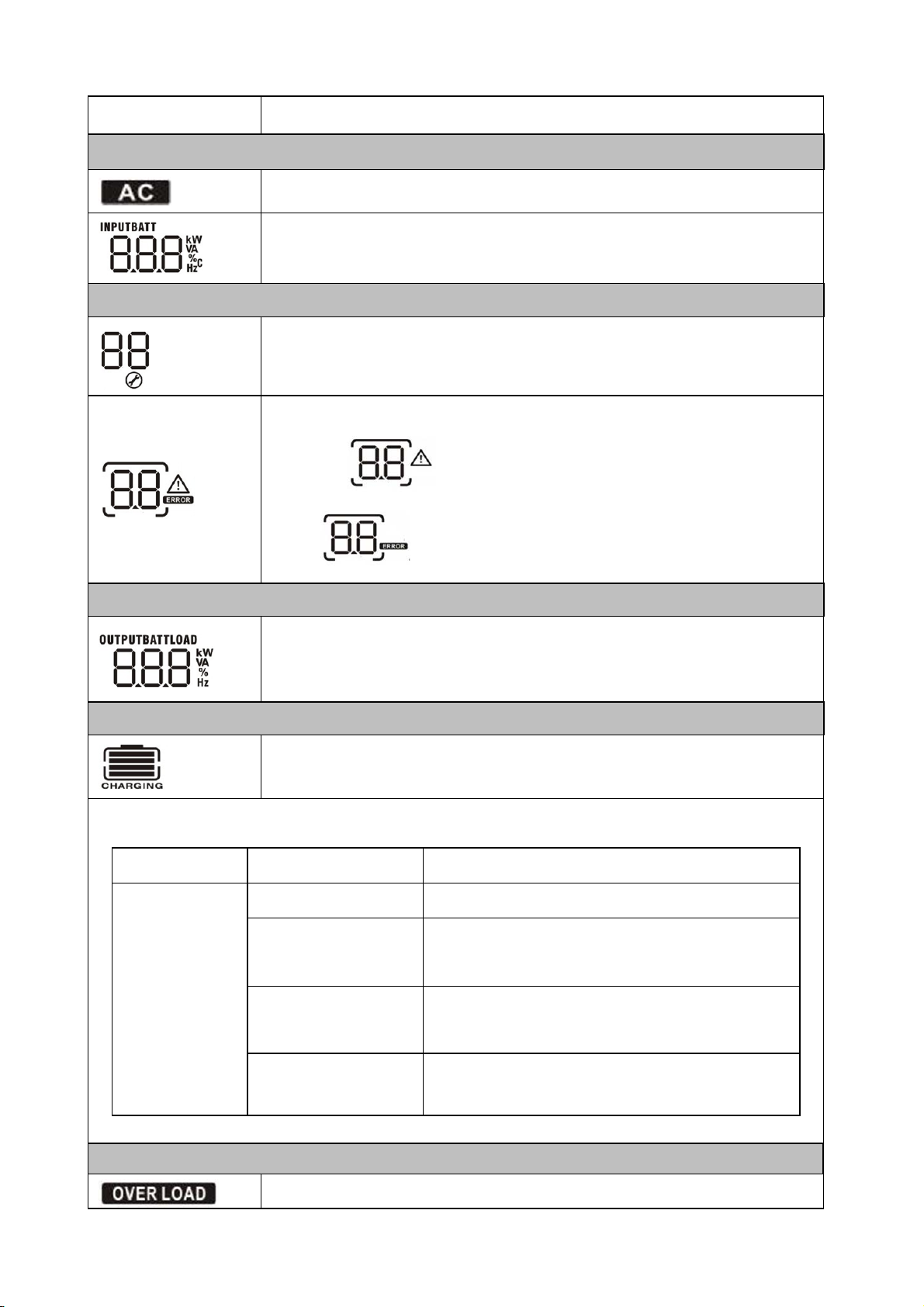
LCD Display Icons
11
Icon
Functiondescription
InputSourceInformation
IndicatestheACinput.
Indicateinputvoltage,inputfrequency,PVvoltage,batteryvoltage
and Temp
Configuration Program and Fault Information
Indicatesthesettingprograms.
Indicatesthewarningand faultcodes.
Warning: flashingwithwarningcode.
Fault: lighting withfaultcode
OutputInformation
Indicate output voltage, output frequency, load percent, load in VA,
load in
Watt and discharging current.
Battery Information
Indicates battery level by 0-24%, 25-49%, 50-74% and 75-100% in
battery mode and charging status in line mode.
In AC mode, it will present battery charging status.
Status Battery capacity LCD Display
ConstantCurre
n mode
0-24% 4 bars will flash in turns
25-49% Bottom bar will be on and the other three
bars will flash in turns
50-74% Bottom two bar will be on and the other two
bars will flash in turns
75-100% Bottom three bar will be on and thetop bars
will flash
Load Information
Indicatesoverload.

12
Indicatestheloadlevelby 0-24%,25-50%,50-74%and75-100%.
0%~25% 25%~50% 50%~75% 75%~100%
Mode Operation Information
Indicatesunitconnectstothemains.
Indicatesloadissuppliedbyutilitypower.
Indicatestheutilitychargercircuitis working.
IndicatestheDC/ACinvertercircuitis working.
Mute Operation
Indicatesunitalarmisdisabled.
3. Operations
3-1 Button operation
Button
Function
ON /ENTER Button
Turn on the UPS: Press and hold ON button for
at least 2 seconds to turn on the UPS.
Confirmcurrentsettings:When the UPS
entersthe setting mode, must press this button
to confirm thesettingsvalue what you
want,nest press up/downbutton to
changesettings information
Out off bypass mode:when the UPS enter to
bypass mode, press and hold this button it will
switch to normal mode.
OFF/ESC Button
Turn off the UPS: Press and hold this button at
least 2 seconds to turn off the UPS in battery
mode. UPS will be in standby mode under
power normal or transfer to Bypass mode if the
Bypass enable setting by pressing this button.
Exit setting mode:Press this button to confirm
selection and exit setting mode when LCD
display the last selection in UPS setting mode.
13
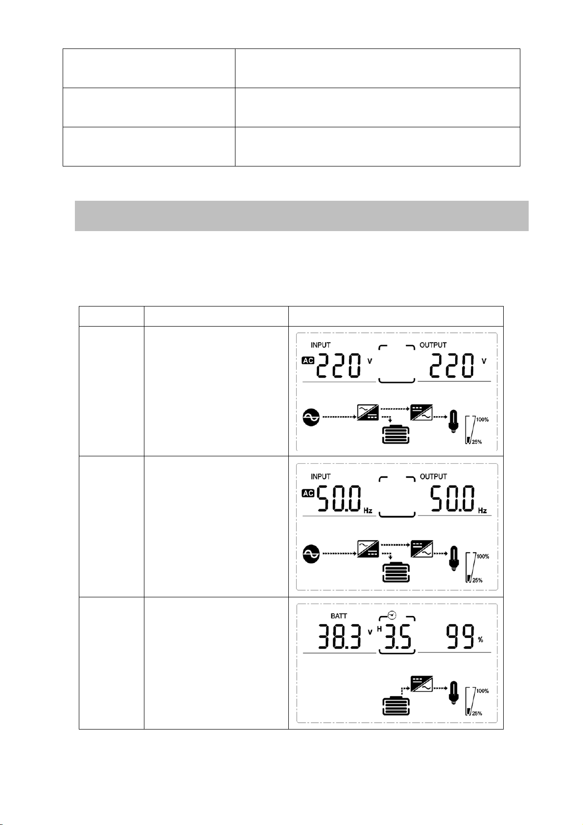
3-2 LCD display
Part one: Rack display
There are 9 interfaces available in the LCD display.
Item Interface Description Content Displayed
01 Input voltage& Output
voltage
02
Input frequency&
Output frequency
03 Battery voltage&
Batterycapacity
UP Button Up key: Press this button to display previous
selection in UPS setting mode.
DOWN Button Down key: Press this button to display next
selection in UPS setting mode.
UP + DOWN Button Setting mode: Press and hold this button for 5
seconds to enter UPS setting mode.

14
04 Load
05 Environment
Temperature
06 UPS model.
07 Firmware Version
08
Alarm Code(Warming
Message)
All alarm codes are
present when abnormal
behavior(s) occur(s)

15
3-3 UPS setting
TheUPS has setting functions. This user settings can be done under any kind of UPS
working mode. The setting will take effect under certain condition. Below table
describes how to set the UPS.
The setting functioniscontrolled by 4buttons (Up ,Down, ON/Enter,OFF/ESC):
Up ▲+OFF/Down▼---goes into the setting page,
ON/Enter ---- confirmthe settingsoptions
Up ▲ &Down ▼---value adjustment Or for choosing different pages.
After the UPS turn ON, press buttons “▲&▼” for 5seconds and then goes into the
setting interface page.
Note: Press “Down”button to confirm selection and exit setting mode when LCD
display the last selection in UPS setting mode.
Item Settings Content display
01
Mode setting
Press Enter button to change the
setting (ECO or NOR or CF or
GEN).
Press UP ▲button to select the
previous setting.
Press DOWN▼button to select
the next setting.
02
Output voltage setting
Press Enter button to change
thesetting(208,220, 230, 240).
Press UP▲button to select the
previous setting.
Press DOWN▼buttonto select
the next setting.
03
Frequency setting
Press Enter button to change
the setting (50 or 60Hz).
Press UP button▲to select the
previous setting.
Press DOWN button▼to select
the next setting.
16
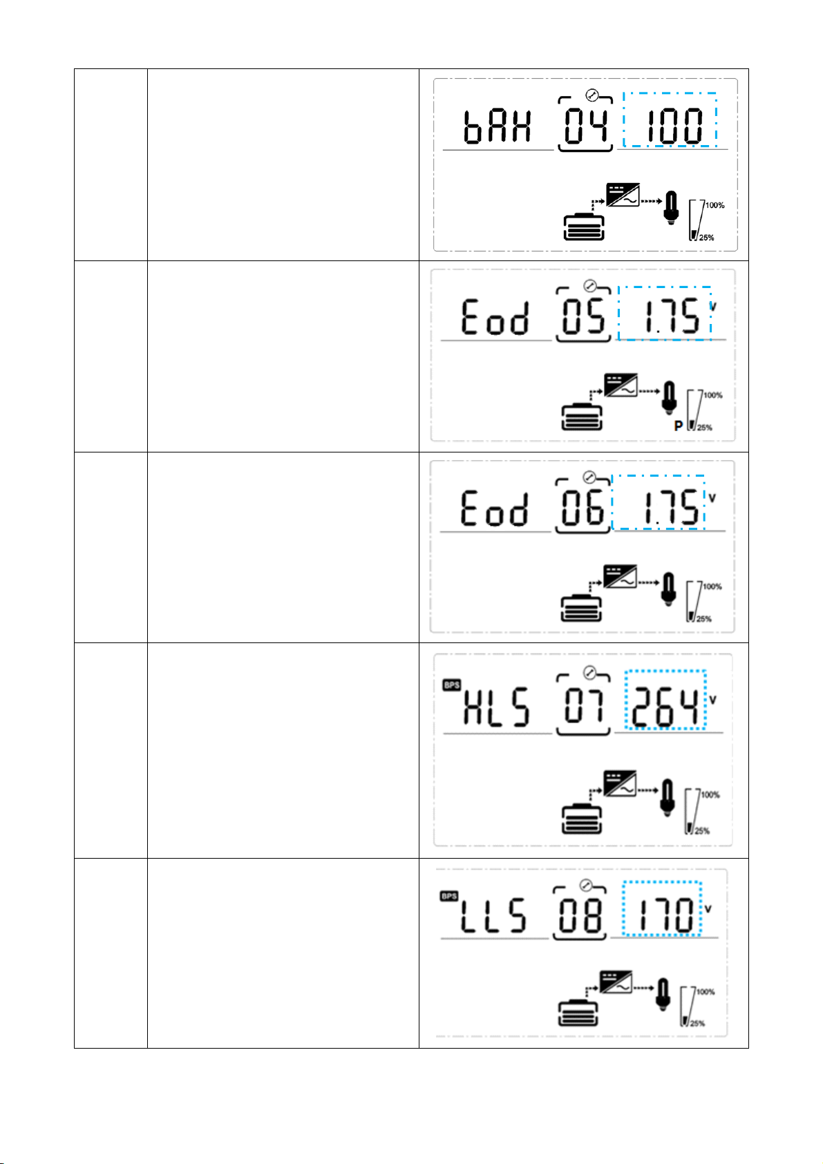
04
Battery capacity setting
Press Enterbutton to change the
setting (Battery capacity range is
1-200Ah).
Press UP button ▲ to select the
previous setting.
Press DOWN button ▼to select
the next setting.
05
Battery EOD voltae setting(Once)
Press Enterbutton to change the
setting (1.75/1.84/1.92).
Press UP button ▲ to select the
previous setting.
Press DOWN button ▼to select
the next setting.
06
Battery EOD voltae
setting(Second)
Press Enterbutton to change the
setting (1.60/1.70/1.75/1.80).
Press UP button ▲ to select the
previous setting.
Press DOWN button ▼to select
the next setting.
07
Bypass voltage upper limit setting
Press Enterbutton to change the
setting(The bypass voltage upper
limit range is 230-264Vac ).
Press UP button ▲ to select the
previous setting.
Press DOWN button ▼ to select
the next setting.
08
Bypass voltage lower limit setting
Press Enter button to change the
setting(The bypass voltage lower
limit range is 170-220Vac).
Press UP button to select the
previous setting.
Press DOWN button to select
the next setting.

17
09
Mute setting
Press Enter button to change
thesetting(ON or OFF).
Press UP button to select the
previous setting.
Press DOWN button to save and
exit the setup.
10
BYPASS enable/disable setting
Press Enter button to change
thesetting(ON or OFF).
Press UP button ▲ to select the
previous setting.
Press DOWN button ▼ to save
and exit the setup.
3-4 Operational Status and Mode(s)
item Content Displayed
2 Standby Mode
3 No Output
4 Bypass Mode
5 Utility Mode
6 Battery Mode
7 Battery Self-diagnostics
8 Inverter is starting up
9 ECO Mode
10 EPO Mode
11 Maintenance Bypass Mode
12 Fault Mode
13 Generator Mode

18
3-5 Alarm or Fault reference code
Event log
UPS Alarm Warning Buzzer LED
1
Rectifier Fault Beep continuously Fault LED lit
2 Inverter fault(Including Inverter bridge
is shorted) Beep continuously Fault LED lit
9
Fan fault Beep continuously Fault LED lit
12
Selftest fault Beep continuously Fault LED lit
13
Battery Charger fault Beep continuously Fault LED lit
15
DC Bus over voltage Beep continuously Fault LED lit
16
DC Bus below voltage Beep continuously Fault LED lit
17
DC bus unbalance Beep continuously Fault LED lit
18
Soft start failed Beep continuously Fault LED lit
19 Rectification model
Over Temperature Twice per second Fault LED lit
20
Inverter model Over Temperature
Twice per second
Fault LED lit
26
Battery over voltage Once per second Fault LED blinking
29
Output Short-circuit Once per second Fault LED blinking
30
Input current limit Once per second Fault LED blinking
31
Bypass over current
Once per second
BPS LED blinking
32 Overload Once per second INV or BPS LED blinking
33 No battery Once per second Battery LED blinking
34
Battery under voltage Once per second Battery LED blinking
35 Battery low pre-warning Once per second Battery LED blinking
36 Over load time out Once per 2 seconds Fault LED blinking
37 DC component over limit. Once per 2 seconds INV LED blinking
39
Mains volt. Abnormal Once per 2 seconds Battery LED lit
40
Mains freq. abnormal Once per 2 seconds Battery LED lit
41
Bypass Not Available BPS LED blinking
42 Bypass out of tracking range BPS LED blinking
45 EPO Enable Beep continuously Fault LED lit

19
4. Troubleshooting
If the UPS system does not operate correctly, please solve the problem by using the
table below and the Trouble Shooting Chart.
Symptom Possible cause Remedy
No indication and alarm even
though the mains is normal.
The AC input power is not
connected well.
Check if input power cord
firmly connected to the
mains.
The AC input is connected to
the UPS output.
Plug AC input power cord to
AC input correctly.
Alarm code is shown as“33” and
battery led blinking.
The external or internal
battery is incorrectly
connected.
Check if all batteries are
connected well.
Alarm code is shown as “26” and
battery led blinking.
Battery voltage is too high or
the charger is fault.
Contact your dealer.
Alarm code is shown as “34” and
battery led blinking
Battery voltage is too low or
the charger is fault. Contact your dealer.
Alarm code is shown as “32” and
INV or BYPASS led blinking.
UPS is overload Remove excess loads from
UPS output.
Alarm code is shown as “29” and
FAULT led light.
The UPS shut down
automatically because short
circuit occurs on the UPS
output.
Check output wiring and if
connected devices are in
short circuit status.
Alarm code is shown as “9” and
FAULT led light.
Fan fault. Contact your dealer.
Alarm code is shown as “01,02,
15,16,17,18”
A UPS internal fault has
occurred. Contact your dealer.
Battery backup time is
shorter than nominal value
Batteries are not fully
charged
Charge the batteries for at
least 5 hours and then check
capacity. If the problem still
persists, consult your dealer.
Batteries defect
Contact your dealer to
replace the battery.
This manual suits for next models
5
Table of contents
Other Chuphotic UPS manuals


