Equipter RB4000 User manual

Catalog No. E4000OM-0416
April 13, 2016
New Heights LLC
11 Township Drive
Paradise, PA 17562
Phone: 717-768-0070 • Fax: 717-768-8910
Web: www.equipter.com
Equipter
Operators Manual
Model RB4000


New Heights LLC
11 Township Drive
Paradise, PA 17562
Phone: 717-768-0070 • Fax: 717-768-8910
Web: www.equipter.com
CAT E4000OM-0416 i 04/13/16
All rights reserved. No part of this publication may be reproduced, stored in a retrieval system, or transmitted
in any form or by any means, electronic, mechanical, photocopying, recording, or otherwise, without prior
written permission of New Heights, LLC.
Additional manuals can be ordered for a fee from New Heights, LLC. Toll Free 717-768-0070.
COPYRIGHT 2011 by
New Heights, LLC
DISCLAIMER
The information in this manual is provided to promote the safe use of, and assist the operator in achieving the
best performance from Equipter described herein, for their intended applications.

New Heights LLC
11 Township Drive
Paradise, PA 17562
Phone: 717-768-0070 • Fax: 717-768-8910
Web: www.equipter.com
04/13/16 ii CAT E4000OM-0416
Figure 1. Operating and Maintenance Positions .................................................................................. 2
Figure 2. Decals ....................................................................................................................................... 3
Figure 3. Danger Decal, Electrocution Hazard...................................................................................... 5
Figure 4. Equipter Positioned Under Roof. ........................................................................................... 8
Figure 5. Equipter dumping into truck................................................................................................... 8
Figure 6. VIN Label, Tire and Loading Information Placard................................................................. 9
Figure 7. Connection to Tow Vehicle. .................................................................................................... 9
Figure 8. Wheel Lift Lever. .................................................................................................................... 10
Figure 9. Chains, Latch, Break-Away Cable........................................................................................ 10
Figure 10. Platform Latch and Wheel Lift Safety Lock........................................................................11
Figure 11. Parking Brake Lever. ........................................................................................................... 12
Figure 12. Parking Brake Adjustment. ................................................................................................. 12
Figure 13. Fluid Levels. ......................................................................................................................... 12
Figure 14. Grease Fittings Locations................................................................................................... 13
Figure 15. Ignition Switch, Choke, Fuel Shutoff and Pull Start. ........................................................ 14
Figure 16. Throttle at Operator Station................................................................................................ 14
Figure 17. Forward/Reverse and Steering Levers. ............................................................................ 16
Figure 18. Bubble Level Indicator. ....................................................................................................... 16
Figure 19. Outrigger Levers.................................................................................................................. 16
Figure 20. Decal-Raise or Lower Steering Wheels. ............................................................................ 16
Figure 21. Front Outriggers with blocking. ......................................................................................... 17
Figure 22. Rear Outriggers with blocking. .......................................................................................... 17
Figure 23. Decal-Operator Contact Possible....................................................................................... 17
Figure 24. Flaps Open Under Roof....................................................................................................... 18
Figure 25. Roll Back, Lift, Dump and Tailgate Levers. ....................................................................... 19
Figure 26. Dumping debris from Dump Box. ...................................................................................... 19
Figure 27. Preparing to Store the Mats................................................................................................ 19
Figure 28. Mat Storage. ......................................................................................................................... 19
Figure 29. VIN Label, Tire and Loading Information Placard............................................................. 21
IllustratIons

New Heights LLC
11 Township Drive
Paradise, PA 17562
Phone: 717-768-0070 • Fax: 717-768-8910
Web: www.equipter.com
CAT E4000OM-0416 iii 04/13/16
INTRODUCTION............................................................................................................................................ 1
REPORTING SAFETY DEFECTS ................................................................................................................. 1
WARRANTY ................................................................................................................................................... 2
GENERAL INFORMATION............................................................................................................................. 4
SAFETY PRECAUTION DEFINITIONS ......................................................................................................... 4
PRECAUTIONS.............................................................................................................................................. 4
Safety Requirements ................................................................................................................................ 5
Before You Start ....................................................................................................................................... 6
Operating Precautions.............................................................................................................................. 6
Load Handling Precautions ...................................................................................................................... 6
Transport Precautions .............................................................................................................................. 7
OVERVIEW .................................................................................................................................................... 8
TRANSPORTING ........................................................................................................................................... 8
Steps for Determining Correct Load Limit ................................................................................................ 8
Tow Vehicle............................................................................................................................................... 9
Trailer Connection .................................................................................................................................... 9
Disconnecting the Trailer .........................................................................................................................11
OPERATION..................................................................................................................................................11
Maintenance ............................................................................................................................................11
Engine Operation.................................................................................................................................... 14
DRIVING THE EQUIPTER ........................................................................................................................... 15
Loading and Unloading........................................................................................................................... 15
Outrigger Operation................................................................................................................................ 16
DUMP BOX .................................................................................................................................................. 17
Emptying the Dump Box......................................................................................................................... 19
Optional Mats ......................................................................................................................................... 20
TIRE SAFETY INFORMATION .................................................................................................................... 21
Steps for Determining Correct Load Limit – Trailer ................................................................................ 21
Steps For Determining Correct Load Limit – Tow Vehicle ...................................................................... 23
Glossary of Tire Terminology .................................................................................................................. 23
Tire Safety - Everything Rides On It ....................................................................................................... 26
Tire Safety Tips....................................................................................................................................... 31
VENDOR PARTS LIST................................................................................................................................. 31
SPECIFICATIONS........................................................................................................................................ 32
OPERATIONS CHECKLIST ......................................................................................................................... 33
table of Contents

New Heights LLC
11 Township Drive
Paradise, PA 17562
Phone: 717-768-0070 • Fax: 717-768-8910
Web: www.equipter.com
04/13/16 iv CAT E4000OM-0416
table of Contents

New Heights LLC
11 Township Drive
Paradise, PA 17562
Phone: 717-768-0070 • Fax: 717-768-8910
Web: www.equipter.com
CAT E4000OM-0416 1 04/13/16
INTRODUCTION
This manual is furnished to you, the owner/opera-
tor, as a guide to get the greatest benet from your
Equipter. New Heights, LLC wants you to be able
to get the most use out of your machine through
safe and efcient operation.
Before attempting to operate this machine, carefully
read all sections of this manual. Be sure that you
thoroughly understand all of the safety information
and operating procedures.
Pay special attention to the Safety Precautions and
Requirements, particularly all DANGER, WARN-
ING, and CAUTION notices included in this man-
ual. These items combined, form the guidelines for
promoting a safe and efcient operating environ-
ment, along with continuous, reliable service and
minimum down time.
NOTE: Directional reference is as follows: the
front is toward the hitch, back is the
tailgate, the operator platform is on
the left, hydraulic tank on the right.
Throughout this manual reference
is made to the Transport Position,
Dump Position, Rollback Position
and Lift Position (See Illustration).
NOTE: Some equipment depicted in illustra-
tions may not reect exact production
model congurations.
NOTE: All safety, operating, and servicing
information reects current produc-
tion models at the time of publication
of this manual.
NOTE: New Heights, LLC, reserves the right
to discontinue models at any time,
change specications, and improve
design without notice and without
incurring obligation on goods previ-
ously purchased and to discontinue
supplying any part listed, when the
demand does not warrant production.
REPORTING SAFETY DEFECTS
If you believe that your vehicle has a defect which
could cause a crash or could cause injury or death,
you should immediately inform the National High-
way Trafc Safety Administration (NHTSA) in
addition to notifying New Heights, LLC.
If NHTSA receives similar complaints, it may open
an investigation, and if it nds that a safety defect
exists in a group of vehicles, it may order a recall
and remedy campaign. However, NHTSA cannot
become involved in individual problems between
you, your dealer, or New Heights, LLC.
To contact NHTSA, you may either call
the Vehicle Safety Hotline toll-free at
1-888-327-4236 (TTY: 1-800-424-9153), go to
http://www.safecar.gov or write to:
Administrator
NHTSA
1200 New Jersey Avenue S.E.
Washington, DC 20590
You can also obtain other information about motor
vehicle safety from http://www.safecar.gov.

New Heights LLC
11 Township Drive
Paradise, PA 17562
Phone: 717-768-0070 • Fax: 717-768-8910
Web: www.equipter.com
04/13/16 2 CAT E4000OM-0416
WARRANTY
This Equipter is designed and manufactured to high
quality standards. New Heights, LLC, therefore,
guarantees this machine to be free from defects in
workmanship and materials for one year from pur-
chase date. Warranty provides for replacement parts
but does not include the labor to replace defective
parts.
Figure 1. Operating and Maintenance Positions
Vendor components are warranted separately by
their specic manufacturer.
Warranty does not cover normal wear or failure due
to hydraulic oil contamination.
Misuse, abuse, misapplication, and unauthorized
alterations will void this warranty.
New Heights LLC
11 Township Drive
Paradise, PA 17562
Phone: 717-768-0070 • Fax: 717-768-8910
Web: www.equipter.com
CAT E4000OM-0416 3 04/13/16
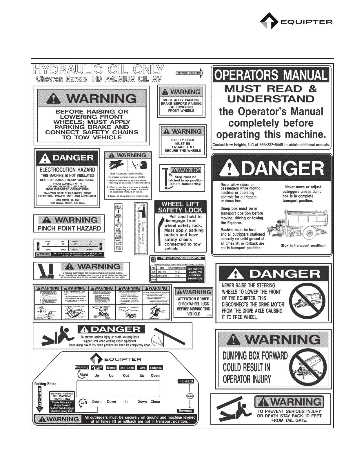
Figure 2. Decals
New Heights LLC
11 Township Drive
Paradise, PA 17562
Phone: 717-768-0070 • Fax: 717-768-8910
Web: www.equipter.com
04/13/16 4 CAT E4000OM-0416
GENERAL INFORMATION
The purpose of this manual is to provide safe oper-
ating and maintenance procedures for the intended
use of this machine. It is important that all informa-
tion in this manual is READ and UNDERSTOOD
before operating the Equipter.
Since the manufacturer has no direct control over
machine application and operation, it is the respon-
sibility of the operator to conform to good safety
practices in the implementation of this machine.
This section is composed of various warnings and
safety tips which must be followed.
SAFETY PRECAUTION DEFINITIONS
Dangers, Warnings, Cautions, and Notes are stra-
tegically placed throughout this manual to further
emphasize the importance of personal safety, qual-
ications of operating personnel, and proper use of
this machine in its intended application.
These precautions supplement and/or complement
the safety information decals afxed to the unit and
include headings that are dened as follows:
Indicates an imminently hazardous situation
which, if not avoided, will result in death or seri-
ous injury.
Indicates a potentially hazardous situation or
practice which, if not avoided, could result in
death or serious injury.
Indicates a potentially hazardous situation or
practice which, if not avoided, will result in dam-
age to equipment and/or minor injury.
Notes are also found in this manual.
NOTE: Provides information which may be
of special interest.
PRECAUTIONS
The primary responsibility for safety with the
equipment falls to the operator. It is the skill, care,
common sense, and good judgement of the operator
that determines how efciently and safely the job is
performed. Know the equipment before you start.
Know the capabilities, dimensions, and how to op-
erate all the controls. Visually inspect the equipment
before starting and never operate equipment that is
not in proper working order with all safety devices
in place and operating.
Modication of the equipment, including remov-
al or modication of safety and identication
decals, without the written consent of the manu-
facturer is a safety violation and is strictly pro-
hibited.
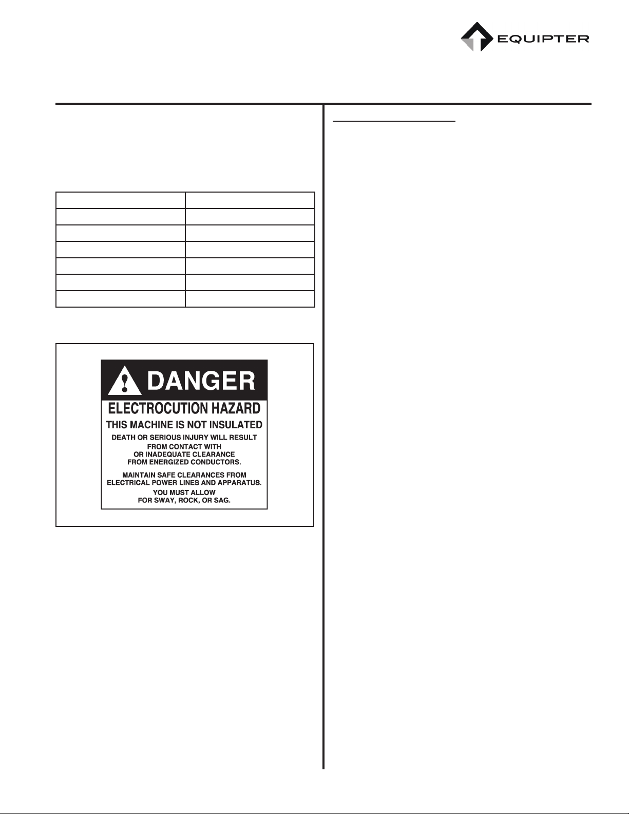
This machine is not insulated and does not pro-
vide protection from contact with or proximity to
an electrically charged conductor.
Working in the vicinity of power lines is a very seri-
ous hazard and special precautions must be taken.
Any overhead wire shall be considered to be an
energized line until the owner of the line or the
electrical utility authorities indicate that it is not an
energized line and it has been visibly grounded.
Contact with power lines is not required for electri-
cal power to arc between the line and equipment.
New Heights LLC
11 Township Drive
Paradise, PA 17562
Phone: 717-768-0070 • Fax: 717-768-8910
Web: www.equipter.com
CAT E4000OM-0416 5 04/13/16
Always be aware of the power carried by the power
lines. Allow sufcient time and distance to react
to swaying or sagging power lines. The following
table provides the minimum distances which should
be maintained.
0 volts to 300 volts Avoid Contact
300 volts to 50 kv 10 ft.(3.05 m)
50 kv to 200 kv 15 ft.(4.6 m)
200 kv to 350 kv 20 ft.(6.1 m)
350 kv to 500 kv 25 ft.(7.6 m)
500 kv to 750 kv 20 ft.(9.2 m)
750 kv to 1000 kv 45 ft.(13.7 m)
Figure 3. Danger Decal, Electrocution Hazard
Safety Requirements
All operators must be 18 years of age or older and
must have the ability to securely engage the parking
brakes.
The parking brakes must always be securely en-
gaged unless the equipment is attached to a tow
vehicle or it is being driven by its own drive system.
The equipment freewheels unless the hydraulic mo-
tor is engaged to the rear axle or the parking brake
is engaged.
Always connect and disconnect the Equipter to the
tow vehicle in a level area. Never lower or raise the
front wheels unless the parking brake is applied and
the safety chains are attached to the tow vehicle.
Never disengage the front wheel safety lock unless
the parking brake is securely applied and the safety
chains are attached to the tow vehicle.
Raising the front wheels for road transportation also
disengages the hydraulic motor from the rear axle
causing it to freewheel for highway towing. When
equipment is secured to tow vehicle hitch, slightly
engage the reverse drive lever to ensure the hydrau-
lic motor has disengaged from the rear axle.
Lowering the front wheels allows the hydraulic mo-
tor to engage to the rear axle. Before releasing the
parking brake and disconnecting the safety chains,
slightly engage the reverse drive lever to ensure the
rear axle has engaged for jobsite use.
Before lifting or extending the dump box out of
transport position always lower all outriggers and
ensure that the Equipter is completely level with all
outriggers rmly stationed on secure footing. Never
lift, lower or adjust outriggers while dump box is
not in the transport position. If any adjustments
need to be made to level the Equipter, always have
the dump box in transport position before moving
the outriggers.
The dump box cannot be dumped without the out-
riggers lowered but never lift or extend the dump
box without the outriggers supporting the Equipter.

New Heights LLC
11 Township Drive
Paradise, PA 17562
Phone: 717-768-0070 • Fax: 717-768-8910
Web: www.equipter.com
04/13/16 6 CAT E4000OM-0416
Always use the bubble level to help conrm that the
Equipter is completely level any time the dump box
is not in the transport position.
The dump box must be in the transport position
(fully forward and down on the frame) before driv-
ing or towing the Equipter.
Always wear a hard hat when operating machine.
Before You Start
Know your equipment. Know how to operate all
controls and know emergency shut down proce-
dures. Make sure all safety devices are in place.
Do not wear loose clothing or items such as rings
and watches around the equipment. They could get
caught in moving parts and lead to serious injury or
death.
Inspect the equipment. Check for missing shields,
loose bolts, twisted or damaged hydraulic hoses. Be
sure all operational decals are in place and legible.
Never operate a damaged or unsafe machine.
Keep all step plates, grab bars, pedals and controls
free of dirt, grease, oil, and water. Keep area clear
of tools, rags, and extra parts. Keep equipment clean
to help avoid injury from a fall when getting on or
off equipment.
Operating Precautions
Know the work area before you begin. Observe any
potential hazard areas such as soft ground, drop-
offs, rocks, and other obstacles.
Do not drive on hills above a 5% grade. Be aware of
wet conditions which may allow the machine to lose
traction and slide on a hill.
Always lower outriggers before raising or extending
the dump box.
Observe overhead electrical and phone lines. Be
sure equipment will safely clear them.
Be aware of others in the work area. Be sure others
know when and where you will be working. Make
sure no one is underneath or behind equipment.
Never try to board equipment while its moving.
Never allow riders or passengers while driving
machine or operating the outrigger controls or dump
box.
This machine is NOT to be used for personnel lift.
Be aware of what is going on around you. Watch for
others who may not be watching out for themselves.
Load Handling Precautions
Ensure machine is level and stabilized and that the
brakes are properly set prior to operating the dump
box.
Check clearance on both sides before outriggers are
lowered. Make sure personnel are clear of outrig-
gers.
Use blocking or cribbing underneath the outriggers
to assist in securely leveling the machine.
Never allow riders or passengers in the dump box
when raising or lowering.

New Heights LLC
11 Township Drive
Paradise, PA 17562
Phone: 717-768-0070 • Fax: 717-768-8910
Web: www.equipter.com
CAT E4000OM-0416 7 04/13/16
Transport Precautions
Always use a tow vehicle with a GVWR capacity
greater than that of the combined Equipter and tow
vehicle weight. The hitch must also be of a rating
greater than that of the Equipter.
Always connect the break-away brake cable to the
tow vehicle. Do not connect to the safety chains or
slide-in.
Always disconnect and park Equipter on level
ground. If disconnecting or parking on level ground
is not possible, use blocking in front and behind rear
wheels to prevent the machine from rolling.
Always use a snap pin or lock to secure the latch in
the locked position over the ball.
Ensure that the dump box is down against the frame
and fully retracted in “transport position” before
transporting.
Ensure that the outriggers are fully raised before
transporting.
Ensure that the front steering assembly is raised and
securely latched before transporting.
Do not transport the unit with the dump bed “aps”
open. This would cause the unit to be over-width.
Do not overload the unit. Be aware of the maximum
load capacity of the Equipter.
Check all lights before transporting the equipment
on public roads. Have an assistant verify brake light
operation.
Conrm trailer brakes work.
Being sure wheel mounting nuts (lug nuts) on trailer
rear wheels are tight and properly torqued.
Lug nuts are prone to loosen right after a wheel is
mounted to a hub. When driving on a new or re-
mounted wheel, check the lug nut tightness often
during the rst few hundred miles of the trailer’s
use, especially after the rst 10, 25 and 50 miles of
driving, before each tow, and at least twice per year
thereafter.
Maintenance Precautions
Replace all safety shields and guards when nished
performing maintenance. Do not operate the equip-
ment with protective equipment removed.
Never perform maintenance or adjustments while
the equipment is operating. Turn off the engine
when performing maintenance to prevent accidental
movement.
Never perform maintenance on this machine un-
less the lift is completely in the down position. The
dump box can be tilted in the dump position secured
with the support arm but never with the dump box
lifted.
Make sure all operating and residual pressures are
relieved before working on a hydraulic system.
Shut engine off and operate all the controls to re-
lieve any pressure.
Use only manufacturer recommended replacement
parts. Other parts may be substandard in t and quality.
New Heights LLC
11 Township Drive
Paradise, PA 17562
Phone: 717-768-0070 • Fax: 717-768-8910
Web: www.equipter.com
04/13/16 8 CAT E4000OM-0416
OVERVIEW
The Equipter is designed for contractors to simplify
a difcult job - cleanup. It takes this labor intensive,
time-consuming job to a level of automation not
found previously. This ingenious machine will not
only simplify your work, it reduces trafc through
carefully manicured ower beds, around fences, and
over shrubbery. Your customers will quickly see the
benets of less wear and tear through their yard.
The Equipter is a simple and durable time saver. It
can be towed to the jobsite by most pickup trucks.
At the jobsite, it is disconnected from the tow ve-
hicle and becomes a self-propelled vehicle. It can
be driven into place across yards and the dump bed
extended and/or raised over fences, shrubbery, and
ower beds.
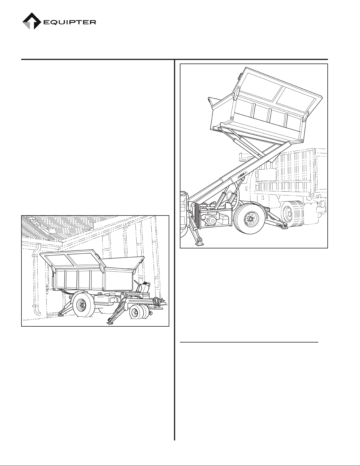
Figure 4. Equipter Positioned Under Roof.
At about 6 feet wide the Equipter ts places where
trucks and trailers do not. Once in position, panels
on the dump bed open to provide nearly 11 feet of
“collection” coverage. The dump bed can be posi-
tioned just under a roof’s overhang to prevent debris
from falling on the ground or driveway.
Figure 5. Equipter dumping into truck.
When the job is done, the Equipter is driven to the
desired location and the debris dumped into a wait-
ing container or truck. The Equipter can clear 11
feet allowing most standard dump trucks to be used
to haul away debris.
TRANSPORTING
Steps for Determining Correct Load Limit
1. Locate the statement “The weight of cargo
should never exceed 1587 kg or 3500 pounds”
on your vehicle’s placard.
2. The gure equals the available amount of
cargo and luggage load capacity.
3. Determine the combined weight of luggage
and cargo being loaded on the vehicle. That
weight may not safely exceed the available
cargo and luggage load capacity calculated in
Step 2.

New Heights LLC
11 Township Drive
Paradise, PA 17562
Phone: 717-768-0070 • Fax: 717-768-8910
Web: www.equipter.com
CAT E4000OM-0416 9 04/13/16
Figure 6. VIN Label, Tire and Loading Information
Placard.
4. If your vehicle will be towing a trailer, load
from your trailer will be transferred to your
vehicle. Consult this manual to determine
how this reduces the available cargo and lug-
gage load capacity of your vehicle.
Tow Vehicle
The tow vehicle must have a tow rating greater than
the GVWR of the Equipter (see specications). In
addition, the vehicle must be equipped with a trailer
hitch. A Class IV hitch is the minimum recommen-
dation.
NOTE: Some Class III hitches are rated for
greater than 5,000 lbs. with a 500 lb.
tongue weight. Most Class IV hitches
are rated for 10,000 lbs. and a 1,000
lb. tongue weight.
The standard hitch on the trailer utilizes a 2-5/16
inch hitch ball and 7 RV trailer plug.
NOTE: An electronic brake controller is
needed.
Hitch balls have ratings similar to hitches. Typ-
ically, a 2-5/16 inch hitch ball with a 1-1/4 inch
shaft is required for towing the Equipter.
Trailer Connection
To connect the Equipter to the tow vehicle it is
easiest to drive it into position although the tow
vehicle can also be backed under the hitch similar to
a standard trailer hook-up.
The outriggers must be fully raised before driving
or towing the Equipter.
Always connect Equipter on level ground. If
connecting on level ground is not possible, use
blocking in front of and behind rear wheels to
prevent the machine from rolling.
1. Using all applicable safety procedures, start
the engine. Refer to the section on Engine
Operation.
2. Drive the Equipter into a position with the
hitch coupler over the hitch ball. Refer to the
section on Driving the Equipter.
3. Engage Parking Brake.
4. Place steering wheels in straight forward posi-
tion.
5. Attach the safety chains to the tow vehicle.
Figure 7. Connection to Tow Vehicle.
New Heights LLC
11 Township Drive
Paradise, PA 17562
Phone: 717-768-0070 • Fax: 717-768-8910
Web: www.equipter.com
04/13/16 10 CAT E4000OM-0416
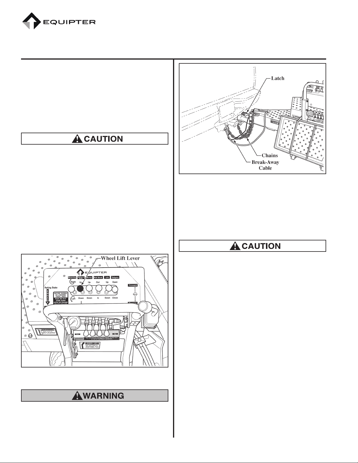
6. Lower the hitch by disengaging the “wheel
lift safety lock” and moving the “Wheel Lift”
control lever in the “Up” direction. This
lowers the trailer hitch by raising the steering
wheels.
7. Secure the trailer to the ball using the latch
mechanism.
The steering wheels, when completely raised,
t inside the frame. They must be in a straight
forward direction for the wheels to properly t
within the frame. Failure to do so will result in
failure to securely lock the steering wheels for
transport.
8. After the weight of the trailer is securely on
the tow vehicle, raise the steering wheels
completely. Ensure the wheels are latched by
trying to lower the wheels without releasing
the safety lock lever.
Figure 8. Wheel Lift Lever.
The parking brake on the Equipter must be
engaged. After the steering wheels are completely
raised, the drive system is disengaged and the
axle will freewheel.
Figure 9. Chains, Latch, Break-Away Cable.
9. To ensure that the drive system has disen-
gaged, slightly engage the drive lever in
reverse.
10. Turn off the engine.
Never transport the Equipter with the engine
running.
11. Raise the operator’s platform and secure using
the latch provided.
NOTE: If the platform does not latch, check
that the front wheels are fully raised
and safety lock is locked in position.
12. Attach the break-away brake cable and elec-
trical plug to the tow vehicle. Place a padlock
or hairpin clip through the latch. Verify that
the safety chains are securely attached to the
tow vehicle.
13. Disengage Parking Brake.
14. Test trailer brakes with brake controller in the
tow vehicle.
15. Test the brake, signal, tail, and clearance
lights on the trailer.
New Heights LLC
11 Township Drive
Paradise, PA 17562
Phone: 717-768-0070 • Fax: 717-768-8910
Web: www.equipter.com
CAT E4000OM-0416 11 04/13/16
Disconnecting the Trailer
After being towed to the job site, the Equipter can
be disconnected from the tow vehicle.
Always disconnect Equipter on level ground. If
disconnecting on level ground is not possible, use
blocking in front of and behind rear wheels to
prevent the machine from rolling.
1. Engage Parking Brake.
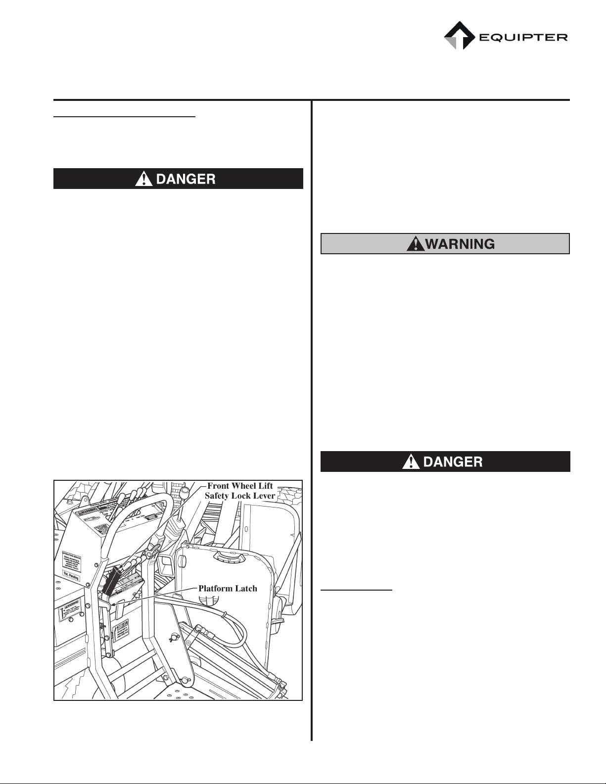
2. Lower the operator’s platform by releasing
the latch.
3. Start the engine using all applicable safety
procedures. Refer to the section on Engine
Operation.
4. Lower the steering wheels until they contact
the ground.
NOTE: Pull and hold to engage front wheel
safety lock. Must apply parking
brakes and have safety chains con-
nected to tow vehicle.
Figure 10. Platform Latch and Wheel Lift Safety Lock.
5. Release the latch that secures the trailer to the
hitch ball.
6. Continue lowering the steering wheels until
the trailer is clear of the hitch ball and the
front wheel safety lock is securely engaged.
7. Slightly engage the drive lever in reverse to
ensure that the drive system is engaged.
Never disengage the Parking Brake or safety
chains unless the drive system is engaged.
8. Disconnect the electrical plug and break-away
brake cable from the tow vehicle. Secure them
to the trailer to prevent dragging or interfer-
ence with operation of the Equipter.
9. Disconnect the safety chains from the tow
vehicle.
10. Disengage Parking Brake.
11. Drive the Equipter away from the tow vehicle.
Always engage the parking brake when parking
the Equipter. Do not park the Equipter on hills
or steep inclines unless blocking is placed in front
of and behind the rear wheels.
OPERATION
Maintenance
While every effort has been made to build a high
quality product, it is important that the Equipter be
maintained and serviced on a regular basis. This
contributes to ensuring reliable equipment that can
be depended on when its needed. Replace all worn
or damaged parts with original manufactured parts.
Never perform maintenance on this machine unless
the lift is in complete transport position. For main-
tenance under the dump box it can be tilted in the
New Heights LLC
11 Township Drive
Paradise, PA 17562
Phone: 717-768-0070 • Fax: 717-768-8910
Web: www.equipter.com
04/13/16 12 CAT E4000OM-0416
dump position and must be secured with the support
arm in place but never have the dump box in the
lifted position.
All personnel must stay off and all body parts out
from under the dump box at all times the lift is not
in the transport position.
Every 8 hours of operation or daily the following
should be checked:
• Check Engine Oil Level - Refer to Engine
Operation Manual.
• Check and adjust parking brake. (See illus-
tration). Ensure that the Parking Brake is
working properly.
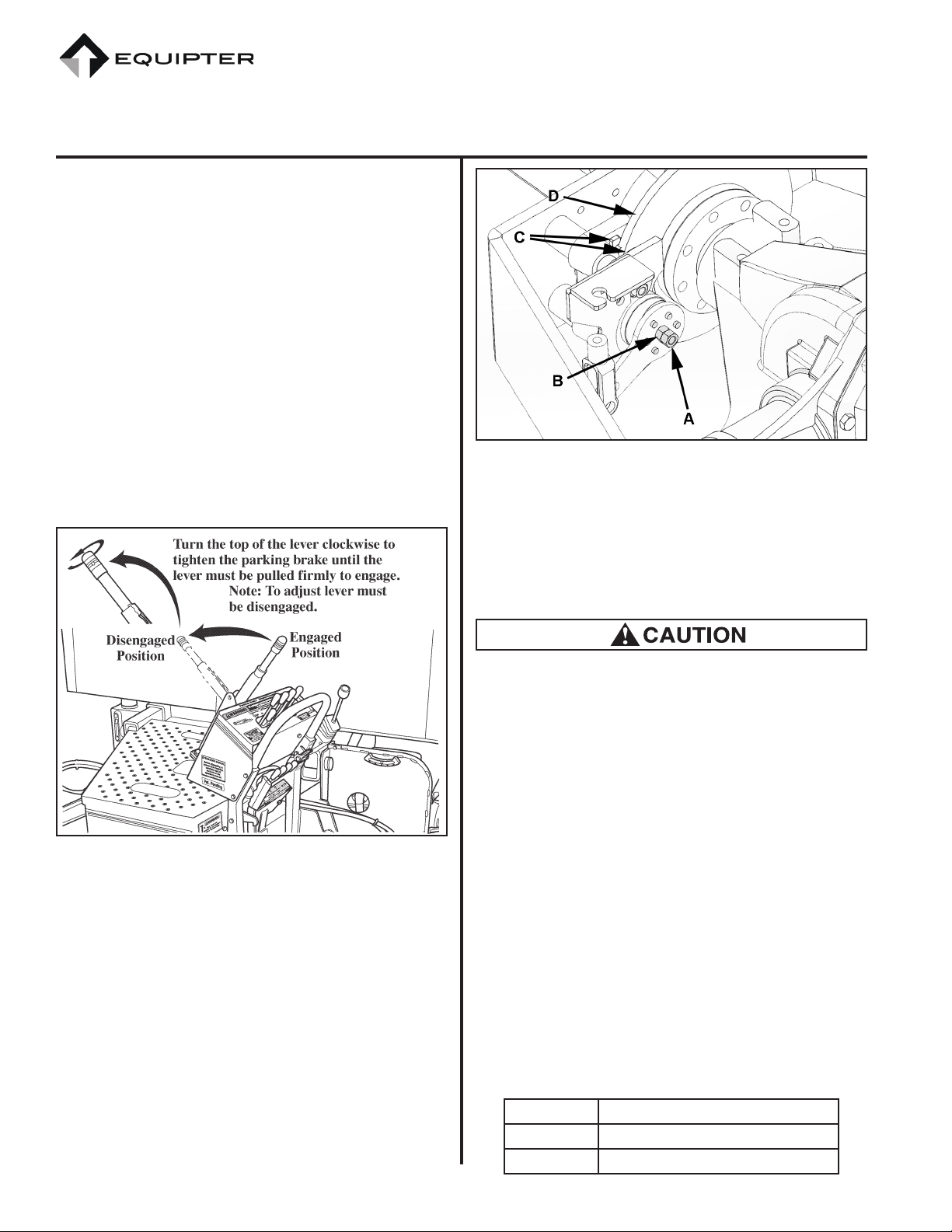
Figure 11. Parking Brake Lever.
• If parking brake does not hold trailer
and lever adjustment is at the maximum,
chock trailer tires and turn knob on top
of lever fully counter clockwise. Loosen
jam nut (A). Tighten nut (B) until there is
approximately a business card clearance
between brake pads (C) and rotor (D)
on each side. Tighten jam nut (A). Adjust
parking brake as shown in gure 11.
Figure 12. Parking Brake Adjustment.
• Check Tire Ination Pressure with tires cold
(not been driven for at least 3 hours). Rec-
ommended ination pressure is on the “Tire
and Loading Information” placard located
on the hitch.
If tires are replaced, be sure they are sized for
the rim and meet or exceed the load capacity of
the original tires supplied by the factory.
• Check Hydraulic Fluid Level - With the
Equipter on level ground, the dump bed
down and retracted, the outriggers raised,
and the steering wheels down, the hydraulic
oil level should be visible in the sight gauge
in between the top and bottom of the tem-
perature gauge (normal reading should be
between 1/4 and 1/2 on the gauge). If nec-
essary to rell, use only approved SAE 5W
hydraulic oil.
New Heights, LLC recommends changing the
hydraulic oil lter every year and the hydraulic oil
every 2 years.
The following are approved oil sources:
Chevron Rando HD Prem MV Hyd Oil
Mobil Mobil DTE 12 or 12M
Castrol Aerial Lift
New Heights LLC
11 Township Drive
Paradise, PA 17562
Phone: 717-768-0070 • Fax: 717-768-8910
Web: www.equipter.com
CAT E4000OM-0416 13 04/13/16
Figure 13. Fluid Levels.
NOTE: Maximum recommended hydraulic
oil operating temperature is 160° F
(71° C).
Every 40 hours of operation or weekly the follow-
ing should be checked:
• Check Tire Ination Pressure - Refer to
“Tire and Loading Information” placard
located on the hitch.
• Check that all wheel lugs nuts are tight. If
not, they must be torqued to the proper spec-
ication.
• Lubricate rollback slide rails - Apply grease
to frame rails where dump box slides. Use
Molybdenum grease (NLGI #2).
• Check rear axle oil level.
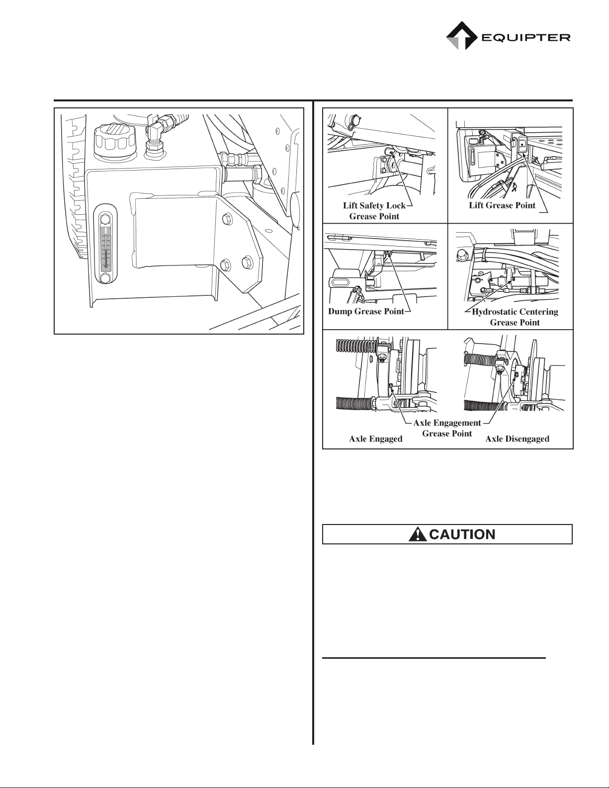
Figure 14. Grease Fittings Locations.
• Lubricate all Grease Fittings - Grease t-
tings are located at most pivot areas.
Be sure to lubricate like items on the opposite
sides of the Equipter.
Worn grease ttings that will not hold the grease
gun, and ttings with a stuck ball, must be re-
placed.
Lubricate the Axle Engagement System
In the drive system is a grease tting. This tting
should be lubricated every 40 hours to ensure prop-
er operation. To access the grease tting:
1. Engage Parking Brake.

New Heights LLC
11 Township Drive
Paradise, PA 17562
Phone: 717-768-0070 • Fax: 717-768-8910
Web: www.equipter.com
04/13/16 14 CAT E4000OM-0416
2. Lower the outriggers.
3. Release the safety latch and raise the front
steering wheels completely.
Place the support arm under the dump box to
provide extra safety while lubricating the axle
engagement system.
4. Tilt the dump box to gain access to the top of
the drive axle. Place the support arm under
the dump box before entering the area under
the dump box.
NOTE: If the grease tting is rotated away
and cannot be accessed, the drive sys-
tem can be operated to spin the drive
shaft. Use the drive control lever to
“bump” the system until the grease
tting is accessible.
5. Apply lubricant as needed.
Engine Operation
This manual is intended to provide an overview of
how the engine works within the Equipter. Addi-
tional information regarding engine operation and
maintenance is available within the Engine Manual
supplied with the machine.
The engine is used to drive a hydraulic pump. The
hydraulic pump then powers various cylinders
and the drive motor. Engine controls consist of a
keyed ignition switch, choke, remote throttle, and
fuel shut-off valve. The ignition switch has three
positions: OFF, RUN, and START. The engine has
a rope pull-start in the event that the battery is not
operational (ignition switch must be in the RUN
position to pull-start).
Figure 15. Ignition Switch, Choke, Fuel Shutoff and Pull
Start.
The throttle is located at the operator station next
to the directional control lever. Press red button in
center of knob to adjust throttle, release button to
lock. More gradual adjustment of throttle can be
made by turning black knob. When starting a cold
engine,pull throttle part way out, slide choke lever
toward the front of the Equipter. After the engine is
running, slowly move the choke into the run posi-
tion. If the engine is warm, choke operation should
not be necessary.
Figure 16. Throttle at Operator Station.
Other manuals for RB4000
2
Table of contents
Other Equipter Utility Vehicle manuals

Popular Utility Vehicle manuals by other brands

Roketa
Roketa GK-19 Owners manual, assembly instructions, and parts manual

Rick's Specialty Vehicles
Rick's Specialty Vehicles Cricket ESV owner's manual

Cushman
Cushman 646442 owner's manual

HAUL MASTER
HAUL MASTER 62645 Owner's manual & safety instructions

Seizmik
Seizmik 06016 Installation & operation manual

Westward
Westward GO-4 EV INTERCEPTOR IV Operator's manual


