Equipter RB4000 User manual

RB4000 OPERATORS MANUAL
855.378.4783
www.equipter.com
49 Eagle Drive, Leola, PA 17540


i
All rights reserved. No part of this publication may be reproduced, stored in a retrieval system, or trans-
mitted in any form or by any means, electronic, mechanical, photocopying, recording, or otherwise, without
prior written permission of New Heights, LLC.
Additional manuals can be ordered for a fee from New Heights, LLC. 717.768.0070
The information in this manual is provided to promote the safe use of, and assist the operator in achieving
the best performance from Equipter products described herein, for their intended applications.
DISCLAIMER
Copyright 2019 by New Heights, LLC
Covered by Patent Number 6817677

INTRODUCTION ................................................................................................................................................................................................1
REPORTING SAFETY DEFECTS..................................................................................................................................................................1
WARRANTY..........................................................................................................................................................................................................2
GENERAL INFORMATION..............................................................................................................................................................................4
SAFETY PRECAUTION DEFINITIONS.......................................................................................................................................................4
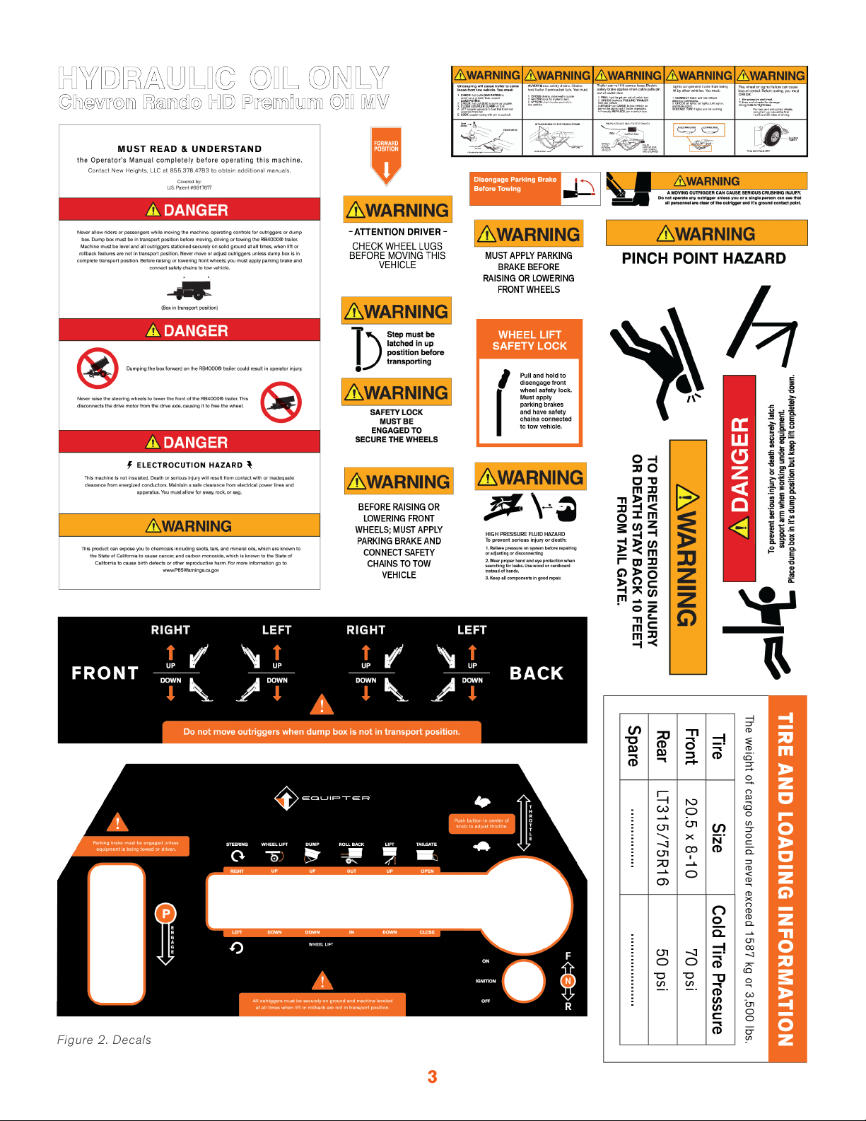
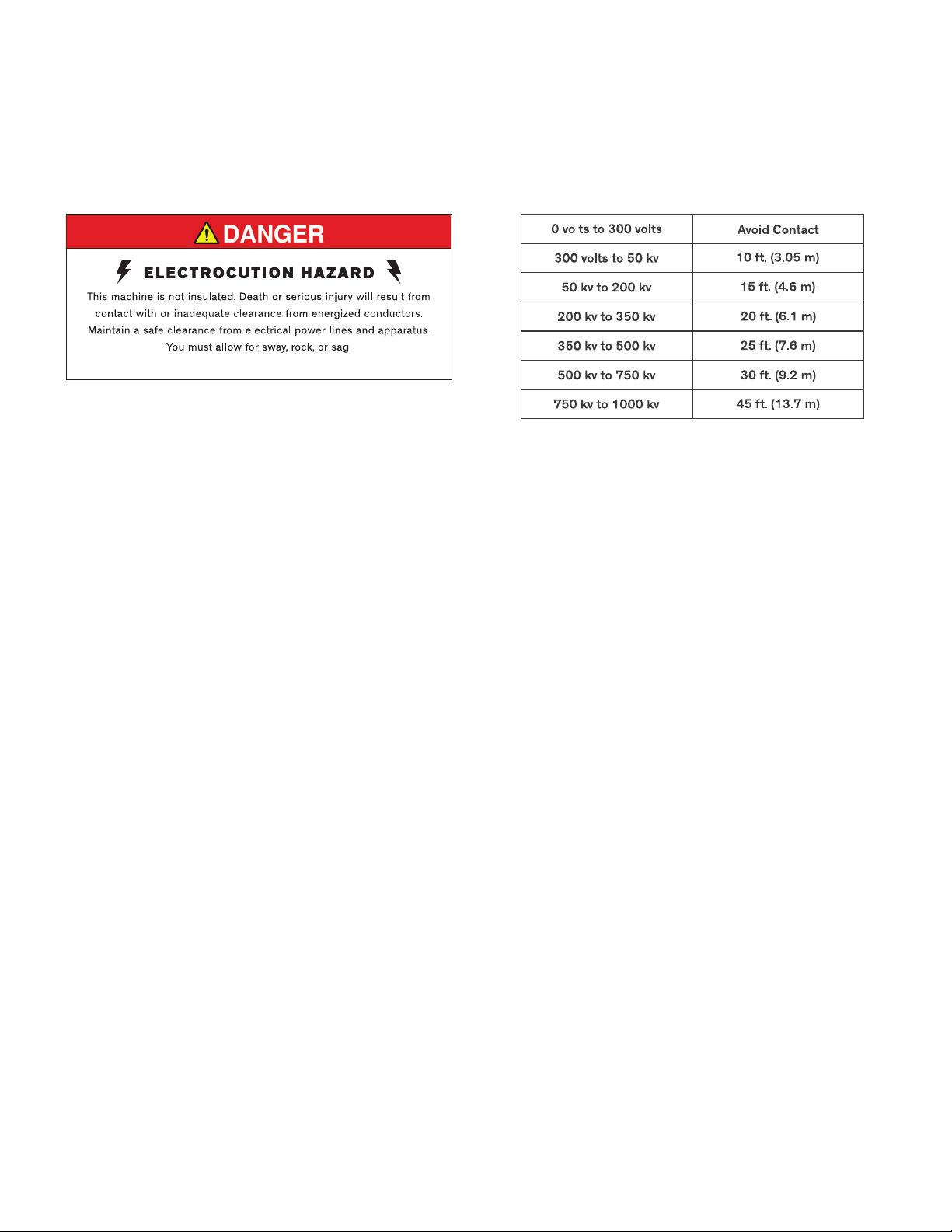
PRECAUTIONS...................................................................................................................................................................................................4
Safety Requirements................................................................................................................................................................................5
Before You Start ........................................................................................................................................................................................6
Operating Precautions.............................................................................................................................................................................6
Load Handling Precautions ...................................................................................................................................................................6
Transport Precautions...............................................................................................................................................................................7
Maintainance Precautions.......................................................................................................................................................................7
OVERVIEW ...........................................................................................................................................................................................................8
TRANSPORTING................................................................................................................................................................................................9
Steps for Determining Correct Load Limit ......................................................................................................................................9
Tow Vehicle ..................................................................................................................................................................................................9
Trailer Connection.................................................................................................................................................................................. 10
Disconnecting the Trailer .................................................................................................................................................................... 11
OPERATION...................................................................................................................................................................................................... 12
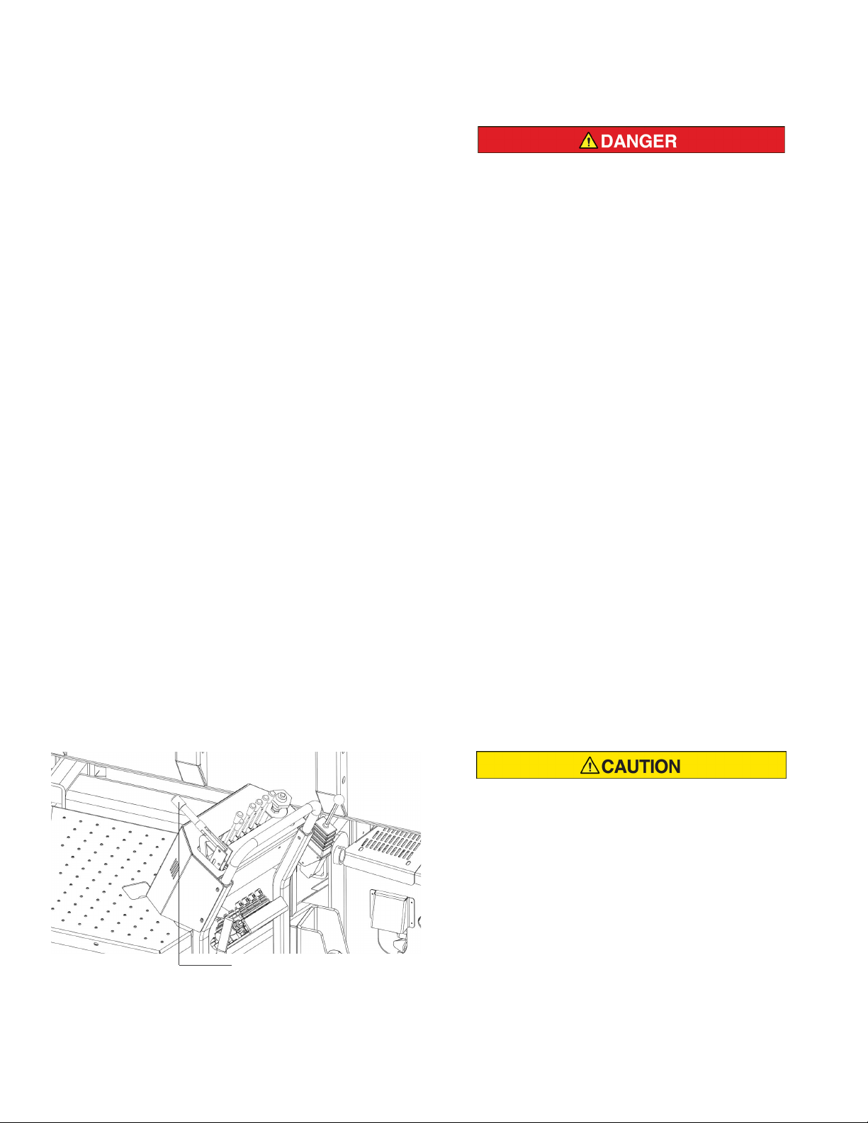
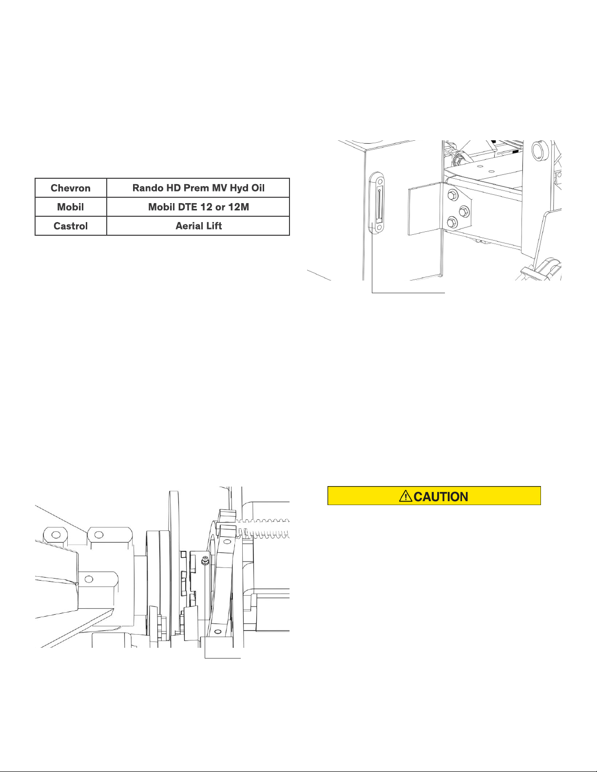
Maintenance............................................................................................................................................................................................. 12
Engine Operation ................................................................................................................................................................................... 14
DRIVING THE EQUIPTER ........................................................................................................................................................................... 15
Loading and Unloading........................................................................................................................................................................ 16
Outrigger Operation .............................................................................................................................................................................. 16
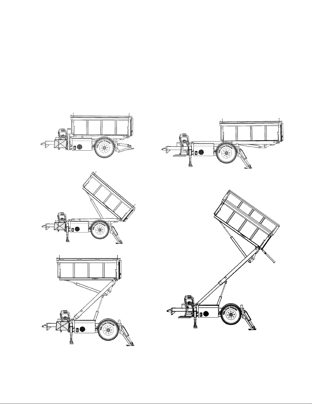
DUMP BOX ....................................................................................................................................................................................................... 18
Emptying the Dump Box...................................................................................................................................................................... 19
EXTENSION RAILS........................................................................................................................................................................................ 20
OPTIONAL MATS............................................................................................................................................................................................ 21
CHUTES............................................................................................................................................................................................................. 21
SPOUTING GUARD ....................................................................................................................................................................................... 22
CHUTE AND SPOUTING GUARD STORAGE....................................................................................................................................... 22
CONTOL PANEL COVER ............................................................................................................................................................................. 22
SPARE TIRE MOUNT AND OUTRIGGER PAD STORAGE............................................................................................................... 22
TIRE SAFETY INFORMATION.................................................................................................................................................................... 23
Steps for Determining Correct Load Limit – Trailer................................................................................................................. 24
Steps For Determining Correct Load Limit – Tow Vehicle..................................................................................................... 25
Glossary of Tire Terminology ............................................................................................................................................................. 26
Tire Safety - Everything Rides On It............................................................................................................................................... 29
Tire Safety Tips ....................................................................................................................................................................................... 34
SPECIFICATIONS........................................................................................................................................................................................... 36
OPERATIONS CHECKLIST ..........................................................................................................................................................................37
TABLE OF CONTENTS
ii

iii
Figure 1. Operating and Maintenance Positions ............................................................................................................................2
Figure 2. Decals ..........................................................................................................................................................................................3
Figure 3. Danger Decal, Electrocution Hazard ................................................................................................................................5
Figure 4. Equipter Positioned Under Roof........................................................................................................................................8
Figure 5. Equipter dumping into truck. ..............................................................................................................................................8
Figure 6. VIN Label, Tire and Loading Information Placard........................................................................................................9
Figure 7. Connection to Tow Vehicle................................................................................................................................................. 10
Figure 8. Wheel Lift Lever.................................................................................................................................................................... 10
Figure 9. Chains, Latch, Break-Away Cable. .................................................................................................................................. 11
Figure 10. Platform Latch and Wheel Lift Safety Lock............................................................................................................. 11
Figure 11. Parking Brake Lever.......................................................................................................................................................... 12
Figure 12. Fluid Levels. ......................................................................................................................................................................... 13
Figure 13. Grease Fittings Locations............................................................................................................................................... 13
Figure 14. Ignition Switch, Choke, Fuel Shutoff and Pull Start. ............................................................................................ 15
Figure 15. Throttle at Operator Station........................................................................................................................................... 15
Figure 16. Forward/Reverse and Steering Levers. .................................................................................................................... 16
Figure 18. Outrigger Levers. ............................................................................................................................................................... 16
Figure 17. Bubble Level Indicator.......................................................................................................................................................17
Figure 19. Decal-Raise or Lower Steering Wheels. ....................................................................................................................17
Figure 20. Front Outriggers with blocking......................................................................................................................................17
Figure 21. Rear Outriggers with blocking.......................................................................................................................................17
Figure 22. Decal-Operator Contact Possible................................................................................................................................ 18
Figure 23. Flaps Open Under Roof................................................................................................................................................... 18
Figure 24. Roll Back, Lift, Dump and Tailgate Levers. .............................................................................................................. 19
Figure 25. Dumping debris from Dump Box.................................................................................................................................. 19
Figure 28. Rear Extension Rails Stored.......................................................................................................................................... 20
Figure 29. Rear Extension Rails Installed. ..................................................................................................................................... 20
Figure 26. Preparing to Store the Mats. ......................................................................................................................................... 21
Figure 27. Mat Storage. ......................................................................................................................................................................... 21
Figure 30. Chutes in Use...................................................................................................................................................................... 21
Figure 31. Chute and Spouting Guard Storage. .......................................................................................................................... 22
Figure 32. VIN Label, Tire and Loading Information Placard.................................................................................................. 25
ILLUSTRATIONS

iv
RIGHT
(Hydraulic Tank Side)
REAR
(Tail Gate)
LEFT
(Operator Side)
FRONT
(Hitch)

1
This manual is furnished to you, the owner/operator, as a guide to get the greatest benefit from your
Equipter. New Heights, LLC wants you to be able to get the most use out of your machine through safe
and efficient operation.
Before attempting to operate this machine, carefully read all sections of this manual. Be sure that you
thoroughly understand all of the safety information and operating procedures.
Pay special attention to the Safety Precautions and Requirements, particularly all DANGER, WARNING,
and CAUTION notices included in this manual. These items combined, form the guidelines for promoting a
safe and efficient operating environment, along with continuous, reliable service and minimum down time.
INTRODUCTION
NOTE: Directional reference is as follows: the front is toward the hitch, back is the tailgate,
the operator platform is on the left, hydraulic tank on the right.
Throughout this manual reference is made to the Transport Position, Dump Position, Rollback
Position and Lift Position (See Illustration).
NOTE: Some equipment depicted in illustrations may not reflect exact production model
configurations.
NOTE: All safety, operating, and servicing information reflects current production models at
the time of publication of this manual.
NOTE: New Heights, LLC, reserves the right to discontinue models at any time, change
specifications, and improve design without notice and without incurring obligation on goods
previously purchased and to discontinue supplying any part listed, when the demand does not
warrant production.
If you believe that your vehicle has a defect which could cause a crash or could cause injury or death,
you should immediately inform the National Highway Traffic Safety Administration (NHTSA) in addition to
notifying New Heights, LLC.
If NHTSA receives similar complaints, it may open an investigation, and if it finds that a safety defect
exists in a group of vehicles, it may order a recall and remedy campaign. However, NHTSA cannot become
involved in individual problems between you, your dealer, or New Heights, LLC.
To contact NHTSA, you may either call the Vehicle Safety Hotline toll-free at 1-888-327-4236
(TTY: 1-800-424-9153), go to http://www.safecar.gov or write to:
Administrator
NHTSA
1200 New Jersey Avenue S.E.
Washington, DC 20590
You can also obtain other information about motor vehicle safety from http://www.safecar.gov.
REPORTING SAFETY DEFECTS

Figure 1. Operating and Maintenance Positions
This Equipter is designed and manufactured to high quality standards. New Heights, LLC, therefore,
guarantees this machine to be free from defects in workmanship and materials for two years from
purchase date. Warranty provides for replacement parts but does not include the labor to replace
defective parts.
Vendor components are warranted separately by their specific manufacturer.
Warranty does not cover normal wear or failure due to hydraulic oil contamination.
Misuse, abuse, misapplication, and unauthorized alterations will void this warranty.
WARRANTY
Lift & Rollback Position
Lift Position
Rollback Position
Transport Position
Dump Position
2

3
Figure 2. Decals

The purpose of this manual is to provide safe operating and maintenance procedures for the intended
use of this machine. It is important that all information in this manual is READ and UNDERSTOOD before
operating the Equipter.
Since the manufacturer has no direct control over machine application and operation, it is the responsibil-
ity of the operator to conform to good safety practices in the implementation of this machine.
This section is composed of various warnings and safety tips which must be followed.
GENERAL INFORMATION
Dangers, Warnings, Cautions, and Notes are strategically placed throughout this manual to further
emphasize the importance of 750 kv to 1000 kv50 kv to 750 kv350 kv to 500 kv200 kv to 350 kv50 kv
to 200 kv300 volts to 50 kv0 volts to 300 voltsThese precautions supplement and/or complement the
safety information decals affixed to the unit and include headings that are defined as follows:
SAFETY PRECAUTION DEFINITIONS
Notes are also found in this manual.
NOTE: Provides information which may be of special interest.
4
The primary responsibility for safety with the equipment falls to the operator. It is the skill, care, common
sense, and good judgement of the operator that determines how efficiently and safely the job is
performed. Know the equipment before you start. Know the capabilities, dimensions, and how to operate
all the controls. Visually inspect the equipment before starting and never operate equipment that is not in
proper working order with all safety devices in place and operating.
PRECAUTIONS
Modification of the equipment, including
removal or modification of safety and
identification decals, without the written
consent of the manufacturer is a safety
violation and is strictly prohibited.
This machine is not insulated and does
not provide protection from contact with
or proximity to an electrically charged
conductor.
Indicates a potentially hazardous situation or
practice which, if not avoided, could result in
death or serious injury.
Indicates an imminently hazardous situation
which, if not avoided, will result in death or
serious injury.
Indicates potentially hazardous situation or
practice which, if not avoided, will result in
damage to equipment and/or minor injury.

Always be aware of the power carried by the power lines. Allow sufficient time and distance to react to
swaying or sagging power lines. The following table provides the minimum distances which should be
maintained.
SAFETY REQUIREMENTS
All operators must be 18 years of age or older and must have the ability to securely engage the parking
brakes.
The parking brakes must always be securely engaged unless the equipment is attached to a tow vehicle
or it is being driven by its own drive system. The equipment freewheels unless the hydraulic motor is
engaged to the rear axle or the parking brake is engaged.
Always connect and disconnect the Equipter to the tow vehicle in a level area. Never lower or raise the
front wheels unless the parking brake is applied and the safety chains are attached to the tow vehicle.
Never disengage the front wheel safety lock unless the parking brake is securely applied and the safety
chains are attached to the tow vehicle.
Raising the front wheels for road transportation also disengages the hydraulic motor from the rear axle
causing it to freewheel for highway towing. When equipment is secured to tow vehicle hitch, slightly
engage the reverse drive lever to ensure the hydraulic motor has disengaged from the rear axle.
Lowering the front wheels allows the hydraulic motor to engage to the rear axle. Before releasing the
parking brake and disconnecting the safety chains, slightly engage the reverse drive lever to ensure the
rear axle has engaged for jobsite use.
Before lifting or extending the dump box out of transport position always lower all outriggers and ensure
that the Equipter is completely level with all outriggers firmly stationed on secure footing. Never lift, lower
or adjust outriggers while dump box is not in the transport position. If any adjustments need to be made
to level the Equipter, always have the dump box in transport position before moving the outriggers.
Never lift or extend the dump box without the outriggers supporting the Equipter.
Figure 3. Danger Decal, Electrocution Hazard
5
Working in the vicinity of power lines is a very serious hazard and special precautions must be taken.
Any overhead wire shall be considered to be an energized line until the owner of the line or the electrical
utility authorities indicate that it is not an energized line and it has been visibly grounded.
Contact with power lines is not required for electrical power to arc between the line and equipment.

Always use the bubble level to help confirm that the Equipter is completely level any time the dump box is
not in the transport position.
The dump box must be in the transport position (fully forward and down on the frame) before driving or
towing the Equipter.
Always wear a hard hat when operating machine.
Know your equipment. Know how to operate all controls and know emergency shut down procedures.
Make sure all safety devices are in place.
Do not wear loose clothing or items such as rings and watches around the equipment. They could get
caught in moving parts and lead to serious injury or death.
Inspect the equipment. Check for missing shields, loose bolts, twisted or damaged hydraulic hoses. Be
sure all operational decals are in place and legible. Never operate a damaged or unsafe machine.
Keep all step plates, grab bars, pedals and controls free of dirt, grease, oil, and water. Keep area clear of
tools, rags, and extra parts. Keep equipment clean to help avoid injury from a fall when getting on or off
equipment.
Ensure machine is level and stabilized and that the brakes are properly set prior to operating the dump
box.
Check clearance on both sides before outriggers are lowered. Make sure personnel are clear of
outriggers.
BEFORE YOU START
LOAD HANDLING PRECAUTIONS
Know the work area before you begin. Observe any potential hazard areas such as soft ground, drop-offs,
rocks, and other obstacles.
Do not drive on hills above a 5% grade. Be aware of wet conditions which may allow the machine to lose
traction and slide on a hill.
Always lower outriggers before raising or extending the dump box.
Observe overhead electrical and phone lines. Be sure equipment will safely clear them.
Be aware of others in the work area. Be sure others know when and where you will be working. Make sure
no one is underneath or behind equipment.
Never try to board equipment while its moving.
Never allow riders or passengers while driving machine or operating the outrigger controls or dump box.
This machine is NOT to be used for personnel lift.
Be aware of what is going on around you. Watch for others who may not be watching out for themselves.
OPERATING PRECAUTIONS
6

Always use a tow vehicle with a GVWR capacity greater than that of the combined Equipter and tow
vehicle weight. The hitch must also be of a rating greater than that of the Equipter.
Always connect the break-away brake cable to the tow vehicle. Do not connect to the safety chains or
slide-in.
Always disconnect and park Equipter on level ground. If disconnecting or parking on level ground is not
possible, use blocking in front and behind rear wheels to prevent the machine from rolling.
Always use a snap pin or lock to secure the latch in the locked position over the ball.
Ensure that the dump box is down against the frame and fully retracted in “transport position” before
transporting.
Ensure that the outriggers are fully raised before transporting.
Ensure that the front steering assembly is raised and securely latched before transporting.
Do not transport the unit with the dump bed “lids” open. This would cause the unit to be over-width.
Do not overload the unit. Be aware of the maximum load capacity of the Equipter.
Check all lights before transporting the equipment on public roads. Have an assistant verify brake light
operation.
Confirm trailer brakes work.
Being sure wheel mounting nuts (lug nuts) on trailer rear wheels are tight and properly torqued.
Lug nuts are prone to loosen right after a wheel is mounted to a hub. When driving on a new or
remounted wheel, check the lug nut tightness often during the first few hundred miles of the trailer’s
use, especially after the first 10, 25 and 50 miles of driving, before each tow, and at least twice per year
thereafter.
TRANSPORT PRECAUTIONS
Replace all safety shields and guards when finished performing maintenance. Do not operate the
equipment with protective equipment removed.
Never perform maintenance or adjustments while the equipment is operating. Turn off the engine when
performing maintenance to prevent accidental movement.
MAINTENANCE PRECAUTIONS
7
Use blocking or cribbing underneath the outriggers to assist in securely leveling the machine.
Never allow riders or passengers in the dump box when raising or lowering.

8
The Equipter is designed for contractors to simplify a difficult job - cleanup. It takes this labor intensive,
time-consuming job to a level of automation not found previously. This ingenious machine will not only
simplify your work, it reduces traffic through carefully manicured flower beds, around fences, and over
shrubbery. Your customers will quickly see the benefits of less wear and tear through their yard.
The Equipter is a simple and durable time saver. It can be towed to the jobsite by most pickup trucks. At
the jobsite, it is disconnected from the tow vehicle and becomes a self-propelled vehicle. It can be driven
into place across yards and the dump bed extended and/or raised over fences, shrubbery, and flower
beds.
At about 6 feet wide the Equipter fits places where trucks and trailers do not. Once in position, lids on the
dump bed open to provide nearly 11 feet of “collection” coverage. The dump bed can be positioned just
under a roof’s overhang to prevent debris from falling on the ground or driveway.
When the job is done, the Equipter is driven to the desired location and the debris dumped into a waiting
container or truck. The Equipter can clear 11 feet allowing most standard dump trucks to be used to haul
away debris.
OVERVIEW
Figure 4. Equipter Positioned Under Roof. Figure 5. Equipter Dumping into Truck.
Never perform maintenance on this machine unless the lift is completely in the down position. The dump
box can be tilted in the dump position secured with the support arm but never with the dump box lifted.
Make sure all operating and residual pressures are relieved before working on a hydraulic system.
Shut engine off and operate all the controls to relieve any pressure.
Use only manufacturer recommended replacement parts. Other parts may be substandard in fit and
quality.

9
Steps for Determining Correct Load Limit
1. Locate the statement “The weight of cargo should never exceed 1587 kg or 3500 pounds” on
your vehicle’s placard.
2. The figure equals the available amount of cargo and luggage load capacity.
3. Determine the combined weight of luggage and cargo being loaded on the vehicle. That weight
may not safely exceed the available
4. If your vehicle will be towing a trailer, load from your trailer will be transferred to your vehicle.
Consult this manual to determine how this reduces the available cargo and luggage load capacity of
your vehicle.
TRANSPORTING
Figure 6. VIN Label, Tire and Loading Information Placard
The tow vehicle must have a tow rating greater than the GVWR of the Equipter (see specifications).
In addition, the vehicle must be equipped with a trailer hitch. A Class IV hitch is the minimum
recommendation.
NOTE: Some Class III hitches are rated for greater than 5,000 lbs. with a 500 lb. tongue
weight. Most Class IV hitches are rated for 10,000 lbs. and a 1,000 lb. tongue weight.
The standard hitch on the trailer utilizes a 2-5/16 inch hitch ball and 7 RV trailer plug.
NOTE: An electronic brake controller is needed.
TOW VEHICLE
Hitch balls have ratings similar to hitches.
Typically, a 2-5/16 inch hitch ball with a
1-1/4 inch shaft is required for towing the
Equipter.

10
Figure 8. Wheel Lift Lever
Figure 7. Connection to Tow Vehicle
To connect the Equipter to the tow vehicle it is easiest to drive it into position although the tow vehicle
can also be backed under the hitch similar to a standard trailer hook-up.
The outriggers must be fully raised before driving or towing the Equipter.
TRAILER CONNECTION
1. Using all applicable safety procedures,
start the engine. Refer to the section on
Engine Operation.
2. Drive the Equipter into a position with the
hitch coupler over the hitch ball. Refer to the
section on Driving the Equipter.
3. Engage Parking Brake.
4. Place steering wheels in straight forward
position.
5. Attach the safety chains to the tow
vehicle.
6. Lower the hitch by disengaging the “wheel
lift safety lock” and moving the “Wheel Lift”
control lever in the “Up” direction. This lowers
the trailer hitch by raising the steering
wheels.
7. Secure the trailer to the ball using the
latch mechanism.
8. After the weight of the trailer is securely
on the tow vehicle, raise the steering wheels
completely. Ensure the wheels are latched by
trying to lower the wheels without releasing
the safety lock lever.
9. To ensure that the drive system has
disengaged, slightly engage the drive lever
in reverse.
10. Turn off the engine.
11. Raise the operator’s platform and secure
using the latch provided.
NOTE: If the platform does not latch, check
that the front wheels are fully raised and
safety lock is locked in position.
Always connect Equipter on level ground. If
connecting on level ground is not possible,
use blocking in front of and behind rear
wheels to prevent the machine from rolling.
The steering wheels, when completely
raised, fit inside the frame. They must be in
a straight forward direction for the wheels
to properly fit within the frame. Failure to do
so will result in failure to securely lock the
steering wheels for transport.
The parking brake on the Equipter must
be engaged. After the steering wheels
are completely raised, the drive system is
disengaged and the axle will freewheel.

11
Figure 9. Chains, Latch, Break-Away Cable
DISCONNECTING THE TRAILER
Figure 10. Platform Latch
12. Attach the break-away brake cable and
electrical plug to the tow vehicle. Place a
padlock or hairpin clip through the latch.
Verify that the safety chains are securely
attached to the tow vehicle.
13. Disengage Parking Brake.
14. Test trailer brakes with brake controller
in the tow vehicle.
15. Test the brake, signal, tail, and clearance
lights on the trailer.
Never transport the Equipter with the
engine running.
After being towed to the job site, the Equipter can
be disconnected from the tow vehicle.
1. Engage Parking Brake.
2. Lower the operator’s platform by releasing
the latch.
3. Start the engine using all applicable
safety procedures. Refer to the section on
Engine Operation.
4. Lower the steering wheels until they
contact the ground.
NOTE: Pull and hold to engage front wheel
safety lock. Must apply parking brakes
and have safety chains connected to tow
vehicle.
5. Release the latch that secures the trailer
to the hitch ball.
6. Continue lowering the steering wheels
until the trailer is clear of the hitch ball
and the front wheel safety lock is securely
engaged.
7. Slightly engage the drive lever in reverse
to ensure that the drive system is engaged.
Never disengage the Parking Brake or safety
chains unless the drive system is engaged.
Always disconnect Equipter on level
ground. If disconnecting on level ground is
not possible, use blocking in front of and
behind rear wheels to prevent the machine
from rolling.
Wheel Lift Safety Lock.

Figure 11. Parking Brake Lever
12
8. Disconnect the electrical plug and break-
away brake cable from the tow vehicle.
Secure them to the trailer to prevent
dragging or interference with operation of
the Equipter.
9. Disconnect the safety chains from the tow
vehicle.
10. Disengage Parking Brake.
11. Drive the Equipter away from the tow
vehicle.
Maintenance
While every effort has been made to build a high quality product, it is important that the Equipter be
maintained and serviced on a regular basis. This contributes to ensuring reliable equipment that can be
depended on when its needed. Replace all worn or damaged parts with original manufactured parts.
Never perform maintenance on this machine unless the lift is in complete transport position. For
maintenance under the dump box it can be tilted in the dump position and must be secured with the
support arm in place but never have the dump box in the lifted position.
All personnel must stay off and all body parts out from under the dump box at all times the lift is not in
the transport position.
Every 8 hours of operation or daily the following should be checked:
• Check Engine Oil Level - Refer to Engine Operation Manual.
• Check and adjust parking brake (1). (See illustration). Ensure that the Parking Brake is working
properly. Rotate top of lever clockwise to tighten parking brake. Note: to adjust, lever must be
disengaged. Pull lever to upright position to engage parking brake. Lever shown disengaged.
OPERATION
Always engage the parking brake when
parking the Equipter. Do not park the
Equipter on hills or steep inclines unless
blocking is placed in front of and behind
the rear wheels.
If tires are replaced, be sure they are
sized for the rim and meet or exceed the
load capacity of the original tires supplied
by the factory.
• Check Tire Inflation Pressure with tires cold (not been driven for at least 3 hours). Recommended
inflation pressure is on the “Tire and Loading Information” placard located on the hitch.

Figure 12. Fluid Levels
Figure 13. Grease Fittings Locations
13
•Check Hydraulic Fluid Level - With the Equipter on level ground, the dump bed down and retracted,
the outriggers raised, and the steering wheels down. The hydraulic oil level should be visible in the
sight gauge in between the top and bottom of the temperature gauge (normal reading should be
between 1/4 and 1/2 on the gauge). If necessary to refill, use only approved hydraulic oil.
New Heights, LLC recommends changing the hydraulic oil filter every 6 months and the hydraulic oil every
3 years.
The following are approved oil sources:
NOTE: Maximum recommended hydraulic oil
operating temperature is 160° F (71° C).
Every 40 hours of operation or weekly the following should be checked:
• Check Tire Inflation Pressure - Refer to “Tire and Loading Information” placard located on the
hitch.
• Check that all wheel lugs nuts are tight. If not, they must be torqued to the proper specification.
• Lubricate rollback slide rails - Apply grease to frame rails where dump box slides. Use multi-
purpose grease (NLGI #2).
• Check rear axle oil level.
• Lubricate all Grease Fittings - Grease fittings are located at most pivot areas.
Be sure to lubricate like items on the
opposite sides of the Equipter. Worn grease
fittings that will not hold the grease gun, and
fittings with a stuck ball, must be replaced.
Grease Zerk

14
Lubricate the Axle Engagement System
In the drive system is a grease fitting. This fitting should be lubricated every 40 hours to ensure proper
operation. To access the grease fitting:
1. Engage Parking Brake.
2. Lower the outriggers.
3. Release the safety latch and raise the
front steering wheels completely.
4. Tilt the dump box to gain access to the
top of the drive axle. Place the support arm
under the dump box before entering the area
under the dump box.
NOTE: If the grease fitting is rotated away
and cannot be accessed, the drive system
can be operated to spin the drive shaft.
Use the drive control lever to “bump”
the system until the grease fitting is
accessible.
5. Apply lubricant as needed.
Engine Operation
This manual is intended to provide an overview of how the engine works within the Equipter. Additional
information regarding engine operation and maintenance is available within the Engine Manual supplied
with the machine.
The engine is used to drive a hydraulic pump. The hydraulic pump then powers various cylinders and
the drive motor. Engine controls consist of a keyed ignition switch, choke, remote ignition switch, remote
throttle, and fuel shut-off valve. The ignition switch has three positions: OFF, ON, and START.
The engine has a rope pull-start in the event the battery is not operational (ignition switch must be in the
ON position to pull-start).
RB4000s produced in 2018 and later feature a remote ignition switch on the operator’s station,
underneath the remote throttle. This allows the operator to easily engage the engine from the control
panel rather than through the engine cage.
The remote ignition switch will only engage if the engine key is in the On position. If the key is switched
to Off, the engine will crank but will not fire.
The throttle is located at the operator station next to the directional control lever. Press red button in
center of knob to adjust throttle, release button to lock. More gradual adjustment of throttle can be made
by turning black knob. When starting a cold engine, pull throttle part way out, slide choke lever toward
the front of the Equipter. After the engine is running, slowly move the choke into the run position. If the
engine is warm, choke operation should not be necessary.
The engine should be turned OFF after the machine is positioned for loading.
Place the support arm under the dump box
to provide extra safety while lubricating the
axle engagement system.
Other manuals for RB4000
2
Table of contents
Other Equipter Utility Vehicle manuals
Popular Utility Vehicle manuals by other brands

WABASH COMMUNICATIONS
WABASH COMMUNICATIONS MBS-1P installation guide

Opus
Opus Off-Road Camper OP15 owner's manual

Winget
Winget 4B2000 Operator's handbook

Buffalo Tools
Buffalo Tools TRDOLLY Assembly instructions

PLAYTIVE JUNIOR
PLAYTIVE JUNIOR MERO Instructions for use

Ditch Witch
Ditch Witch JT30 Operator's manual