Terri 2040 User manual

1
Instruction book
2040
604732
From 199561010

2
Foreword
By studying this Manual you will learn how to
operate and look after your new Terri 2040. For
those of you already familiar with Terri, this
Manual also contains certain information which
you must know.
Apart from lubrication and simpler maintenance
tasks, which you can easily do yourself, you
should let your dealer, who has trained personnel,
be responsible for the servicing.
We reserve the right to change without previous
notice data and equipment, as well as maintenance
and other service instructions.
Manufacturer: Tranells Heby Terrängfordon
THT AB
S-744 31 HEBY, Sweden
Tel: +46-224- 341 40
Fax: +46-224-318 95
Machine type: TERRI 2040
Machine nameplate:
Located to the left in the
front of the engine
compartment
Serial number: .............................
Engine number; .............................

3
ICONTENTS
1 Foreword
1 Manufacturer
1 Machine nameplate
1 Serial number
2 Contents
3 Description
4 Safety
5 Working close to overhead lines
6 Main components of Terri 2040
7 Instrumentation and controls
8 Front dashboard
8 Rear dashboard
15 Driver’s seat
16 Driving instructions
18 Maintenance
18 Diesel engine
20 Fuel system
21 Air lter
22 Cooling system
23 Electrical system
25 Hydraulic system
26 Hydraulic oil tank
27 Tracks-Bogie system
29 Brakes
30 Winch
31 Gearbox
32 Trailer adjustments
33 Lubrication
34 Recommended lubricants
35 Maintenance schedule
36 Troubleshooting
37 Technical specication
39 Alphabetical index

4
DESCRIPTION
TERRI 2040
Terri 2040 is a articulated-steered off-road tracked vehicle (forwarder), with a load capacity of 1.2 m².
Terri 2040 is a special machine with a wide and versatile range of applications.
A 3-cylinder Kubota D1105 diesel engine with precombustion chamber is used as power source in Terri
2040.
Terri 2040 has a hydrostatic/mechanical transmission with a closed hydraulic circuit. The system is
driven by a power-limited variable hydraulic pump, which is directly coupled to the diesel engine. In the
trailer a high-speed hydraulic motor drives a 2-speed preselector gearbox with mechanical differential
lock. The gearbox drives the tracks via two sprocket wheels.
Terri 2040 is easy to operate, having smooth driving charactristics and providing a substantial pulling
power in all situations. The closed hydraulic system is just as effective as a brake as a power unit, when,
for example, the forwarder is driven with a full load down a slope.
The safety cab is spacious and the controls used during normal work are in easy reach of the driver. The
number of functions needed to operate Terri 2040 has been reduced to a minimum. The driver therefore
sits comfortably when both driving and working. The versatile grab-loader is operated with a convention-
al multi-stick system. Different driver seats with mechanical or air suspension are available.
At the front of the machine there is a built-in winch. This can be used to pull the machine loose or to haul
timber from inaccesible terrain.
TRAILER WITH HYDRAULIC DRIVE
The trailer has two low-speed hydraulic motors, which drive the tracks via sprocket wheels. It is
equipped with an automatic hydraulic differential brake. An electric switch in the cab is used to engage
and disengage the trailer drive. When the trailer drive is disengaged, the hydraulic motors are disconnect-
ed at the same time from the load, which enables the trailer to move freely. The highest transport speed is
obtained with the trailer drive disengaged and the gearbox in top gear engaged. The trailer has a built-in
parking brake, which is operated with an electric switch in the cab. When the diesel engine is stopped, the
trailer is automatically braked.
Remember that safety always depends on the driver. Therefore always follow the safety instructions
carefully.
5
SAFETY
This chapter summarizes the rules, which must
always be followed when you are working with
Terri 2040. These rules do not exempt the driver,
however, from taking into account statutory or
other valid national regulations and directives con-
cerning trafc safety and industrial safety.
To be on the safe side
Get throughly acquainted with Terri 2040 and its
operating instructions.
Don’t lend Terri 2040 to anybody who is not used
to operating your machine. You may be held re-
sponsible for any injury or damage that may occur.
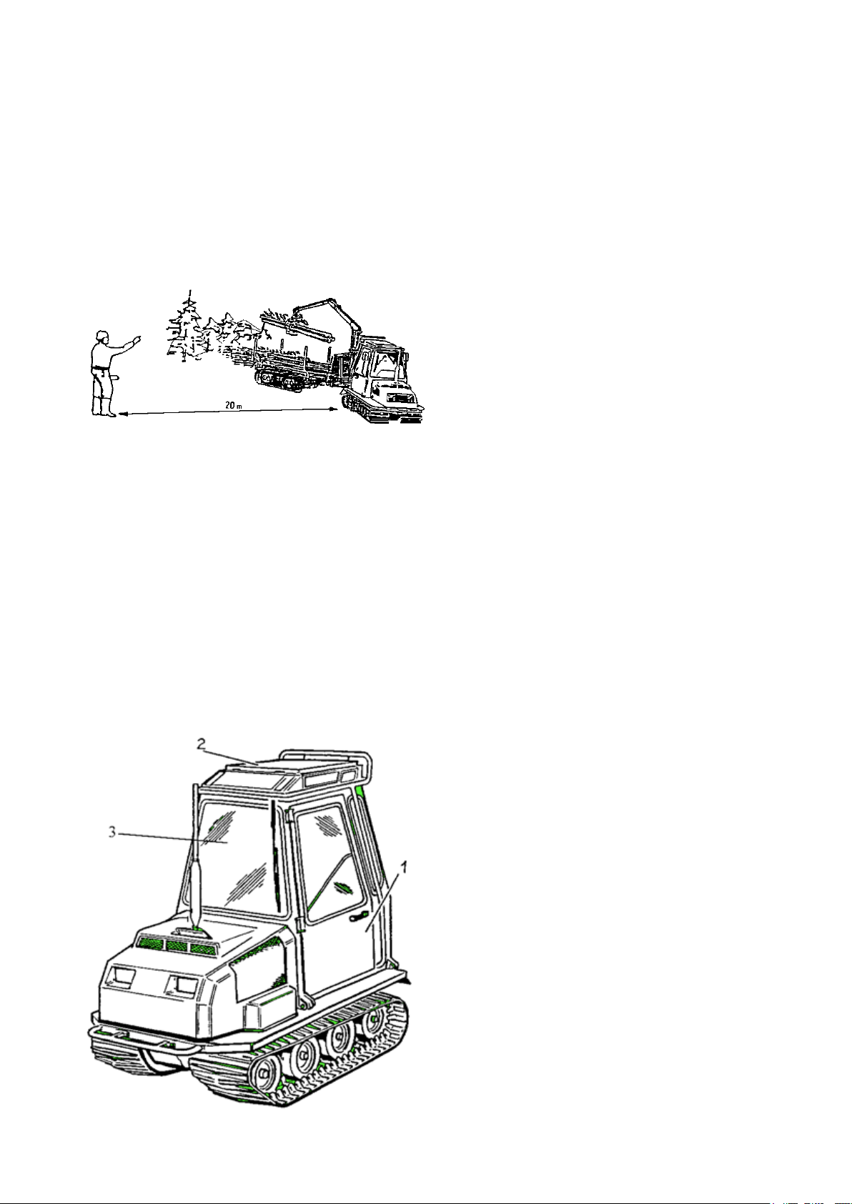
T H E D A N G E R Z O N E I S 2 0 M E T R E S!
Nobody may stay in the danger zone when the
machine is in use.
Terri 2040 does not have any room for a passenger.
Never start the diesel engine, or let it run indoors
in premises with closed doors. Warning for carbon
monoxide poisoning.
If the machine overturns, hold on to the seat or
handles. DON’T JUMP OUT!
Don’t drive the forwarder with a load hanging
from the grab-loader.
Before getting out of your Terri 2040, lower the
gripper, stop the engine and turn off the main
switch.
Don’t walk or stand under a hanging load.
Carry out regularly the maintenance points accor-
ding to the schedule. Before servicing or checking
the machine, always stop the engine.
Familiarize yourself with the emergency exits in
the cab:
1. Side doors 2. Roof opening
The safety bolts of the roof opening must be
withdrawn when you drive on a lake or river cove-
red with ice.
When checking the level of the fuel tank and the
battery electrolyte, never use a naked ame.

6
If possible, inspect in advance the terrain on the
route to be taken, particularly during the winter,
when snow may cover unevenness in the ground.
Note the slope of the terrain and its inuence on
the stability of the tractor.
Be aware of the total height of the grab-loader and
load, before driving anywhere with height restric-
tions. Pay particular attention to any temporary
structures, sagging overhead lines, etc.
Never load the trailer above the height of the load
protection.
Never allow children to stay in the cab or in the vi-
cinity of the machine, when the engine is running.
WORKING CLOSE TO OVERHEAD
LINES
When you are working in the vicinity of elec-
tric overhead lines, no part of the machine or
the load must come closer to the line than the
distances given in the following:
Low voltage 2 metres
High voltage <40 kV 4 metres
High voltage >40 kV 6 metres
If it is difcult to follow the above-mentioned
safety regulations, contact the owner of the over-
head line in order to de-energize it. Under no cir-
cumstances whatsoever can you rely on good luck
when working close to an overhead line. Where
applicable, material must be moved by some other
means a sufcient distance from the overhead line
before it is loaded.
When driving in forests and along forest roads,
remember that it is difcult to see an overhead line
crossing the route. In addition, the line may be
sagging heavily due to snow and ice.
ELECTRICITY DOES NOT NEED ANY DI-
RECT CONTACT. A HIGH VOLTAGE CAN
JUMP ACROSS EVEN LONGER DISTANCES.
7
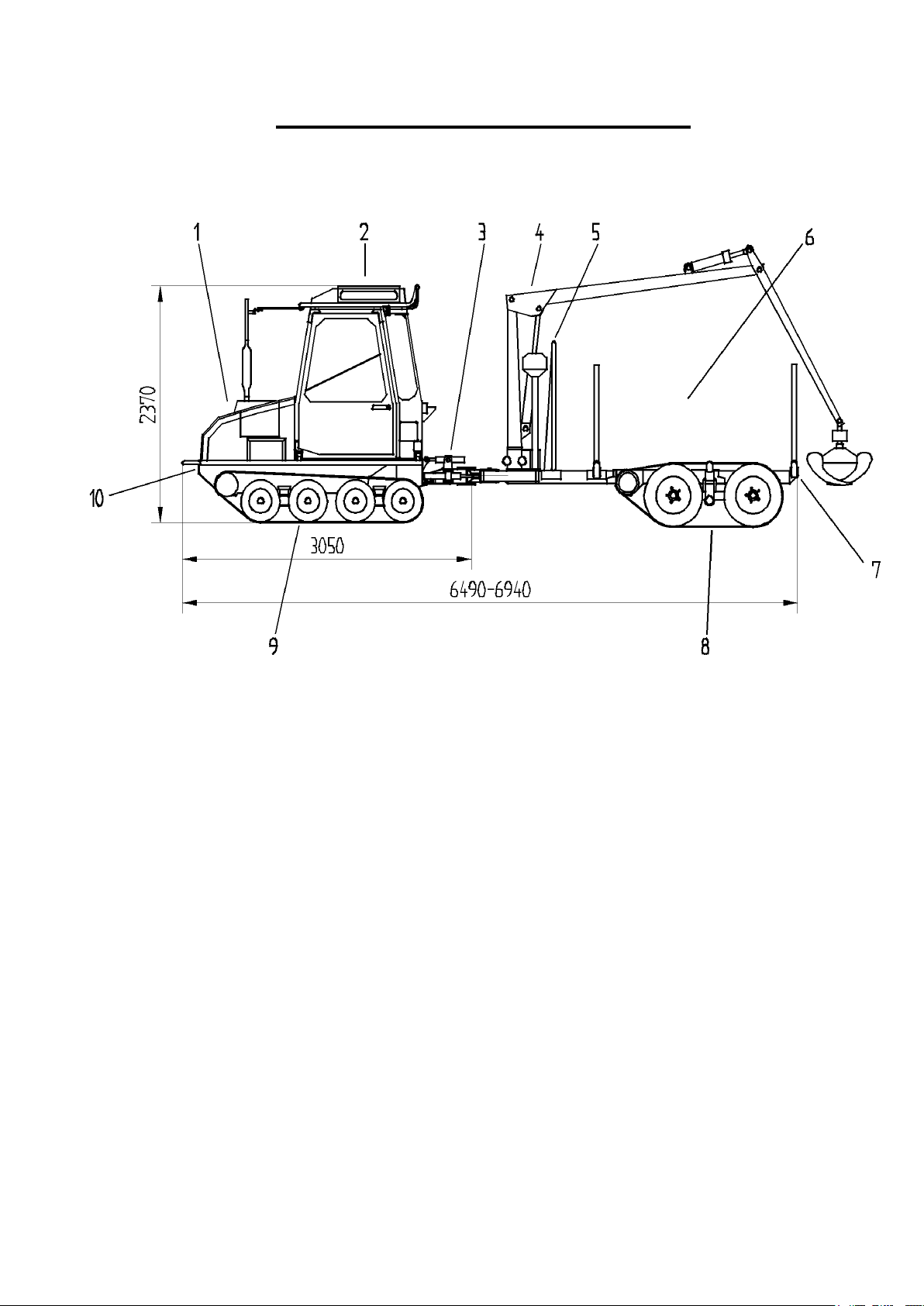
Main components of Terri 2040
1 Drive unit
2 Cab
3 Pulling bar with support cylinder
4 Grab-loader
5 Load shifting protection
6 Load area
7 Trailer
8 Track-bogie system
9 Track-bogie system
10 Winch
8
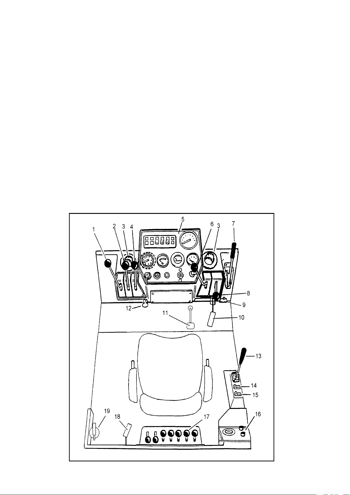
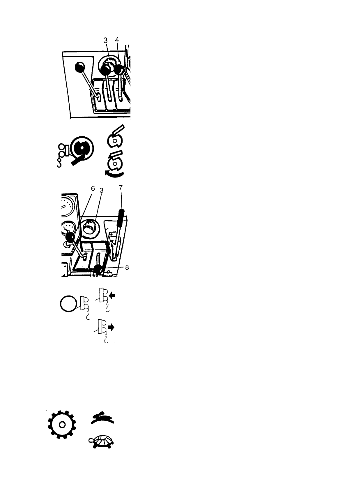
Instrumentation and controls
1 Load cylinder control lever
2 Differential lock (not Sweden)
3 Air vents
4 Winch lock control lever
5 Front dashboard
6 Winch control lever
7 Parking brake
8 Gear shift lever
9 Main switch
10 Accelerator pedal, front
11 Brake (only Sweden)
12 Hand throttle (optional equipment)
13 Drive lever
14 Switch with indicator for trailer drive
15 Switch with indicator for trailer parking brake
16 Rear dashboard
17 Grab-loader controls
18 Accelerator pedal, rear
19 Fire extinguisher

9
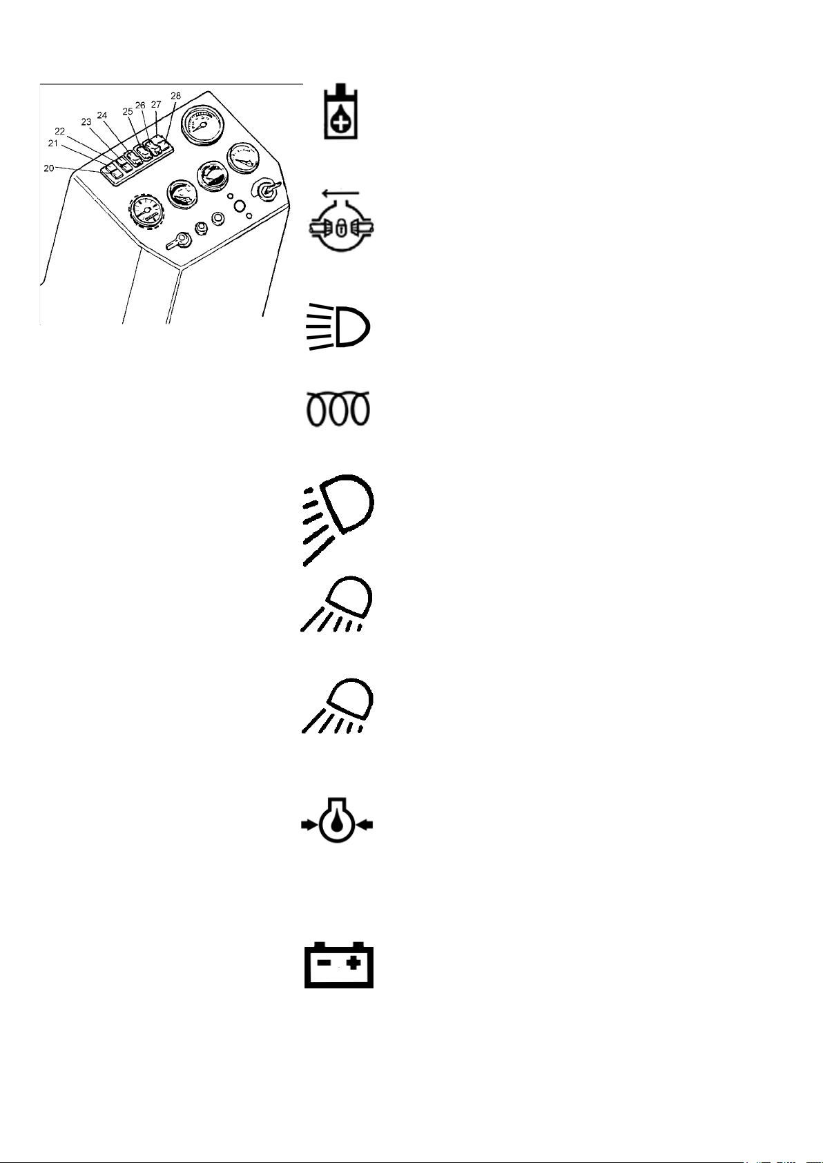
5 Front dashboard
20 Warning light for low hydraulic oil level
21 Warning light for differential lock engaged
22 Indicator for main beams
23 Glow plug indicator
24 Switch with indicator for main-dipped beams
25 Switch with indicator for working lights, side
26 Switch with indicator for working lights, rear
27 Warning light for low oil pressure in diesel engine
28 Charging indicator
29 Tachometer
30 Engine temperature gauge
31 Ignition switch
32 Hydraulic oil temperature gauge
33 Pushbutton for windscreen washer
34 Pushbutton for horn
35 Direction indicator
36 Fuel gauge
37 Running-time meter
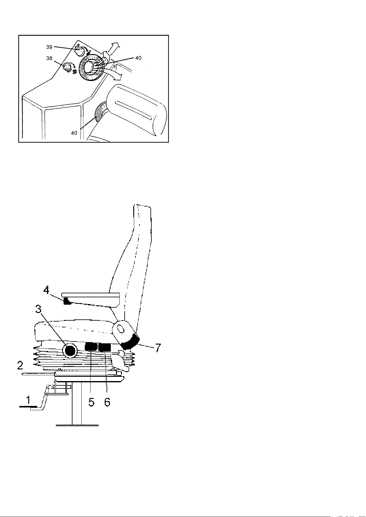
16 Rear dashboard
38 Ventilation blower control
39 Cab heating control
40 Air vents
10
1 Load cylinder
With the help of the load cylinder, which is located
between the tractor and the trailer, it is possible to
adjust the position of the front of the tractor de-
pending on different situations. The load cylinder
is operated with a lever to the left on the dash-
board.
Position 1: The lever pushed upwards = the tractor
‘moves freely’, i.e., the tractor can freely follow
the terrain. It is recommended that this position
should always be used.
N.B. Spring-loaded locking of the lever in this position!
Position 2: The lever in the mid-position, with
spring loading in the centred position = ‘locked
position’. The position of the tractor in relation to
the trailer is locked. It is recommended that this
position should only be used during driving in
loose snow without any track or when the tractor
is driven over a ditch or the like.
Position 3: When the lever is moved forwards, the
front of the tractor is lowered. The lever returns
with spring loading to the ‘locked position’ (2),
when it is released.
CAUTION! Do not turn sharply when the front of
the machine is lowered.
Position 4: When the lever is moved downwards,
the front of the tractor is raised. The lever returns
with spring loading to the ‘locked position’ (2),
when it is released.
Practical example: Driving over a ditch of normal
size:
•Raise the front slightly when approaching the ditch.
•Lower the front before the tractor’s bogie has com-
pletely crossed the ditch so that the front of the bogie
touches the ground on the other side of the ditch.
•Drive the vehicle with the load cylinder in the
locked position until the trailer wheels have
crossed the ditch.
•Continue to drive the vehicle with the load cylin-
der in the ‘free position’.
2 Differential lock
The tractor’s gearbox is provided with a mechani-
cal differential lock, which is controlled with a
lever on the dashboard. When the lever is in its
lowest position, the differential lock is disengaged.
Locked
Free
11
Free
3 Front air vents
The direction of the incoming air is controlled
with the air vents. The air is directed towards the
front windscreen to provide a defroster action.
4 Winch lock
The winch lock prevents the wire rope from run-
ning out. It is operated with a lever to the left on
the dashboard. The winch lock is released when
the lever is in its upper position. Release the
winch lock and draw out the wire rope.
N.B. Wear protective gloves!
N.B. Never drive backwards with the drive lever
while using the winch! This may damage the ge-
arbox.
6 Winch
The winch is operated with a lever to the right
on the dashboard. When the lever is in the up-
per position, the gear in neutral, the trailer drive
disengaged, the drive lever forwards and the ac-
celerator pedal is pushed, the wire rope is wound
up on the drum
N.B. Never drive backwards with the drive lever
while using the winch! This will cause the wire
rope to be wound up in the wrong direction on the
winch drum.
7 Parking brake
This lever actuates a mechanical brake yoke.
When the lever is moved backwards, the machine
is braked. The lock is released with the button at
the end of the lever.
8 Gear shift lever
Two gears can be selected with the lever. If the
lever is moved upwards, the low gear is engaged,
while if the lever is moved downwards, the high
gear is engaged. When the lever stands in the
middle, the gearbox is in neutral.
Disengaged
Engaged
High gear
Low gear
Locked
12
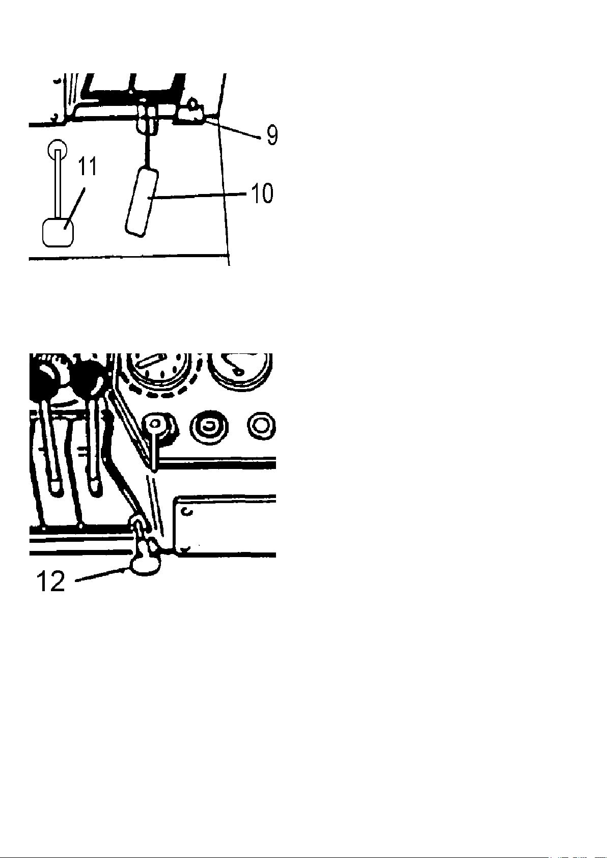
9 Main switch
All the power supply is disconnected with the
main switch.
N.B. Never open the main switch when the engine
is running!
10 Accelerator pedal, front
The engine speed is controlled with the accelerator
pedal during driving.
11 Brake pedal
The machine is braked with the brake pedal.
12 Hand throttle
(optional equipment)
The engine speed can be set with the hand throttle.
Rough setting: press the button and withdraw it.
Fine setting: turn the knob.

13
13 Drive lever
The driving direction and steering are controlled
with the drive lever.
When the drive lever is moved forwards, the
machine goes forwards.
When the drive lever is moved backwards, the
machine goes backwards.
When the drive lever is moved to the right, the
machine turns to the right.
When the drive lever is moved to the left, the
machine turns to the left.
The steering does not automatically return to
‘straight forwards’ but must be moved back with
the drive lever.
The drive lever can be locked in the neutral posi-
tion with the lock.
14 Trailer drive
The trailer drive is engaged and disengaged with
the switch. The indicator shines when the trailer
drive is engaged.
15 Trailer brake
The trailer brake is applied and released with the
switch. The indicator shines when the trailer brake
has been applied. When the oil pressure drops
below 10 bar, the trailer brake is automatically
applied.
N.B. The trailer brake is a parking brake. Always
release the trailer brake when driving the machi-
ne; the brake may otherwise be damaged!
17 Grab-loader controls
See separate instruction manual.
18 Accelerator pedal, rear
The engine speed is controlled with the accelerator
pedal during operation of the grab-loader.
19 Fire extinguisher
The re extinguisher is a 2 kg powder extinguis-
her. See the extinguisher instructions regarding its
use.
Regularly check that the extinguisher’s pressure
gauge eedle stands in the green eld.
When the hydraulic oil level drops to the mini-
mum level, the warning light shines.
Lock
14
20 Warning light for low hydraulic oil level
When the hydraulic oil level drops to the minimum level, the
warning light shines.
21 Warning light fordifferential lock
The indicator shines when the differential lock is
applied.
22 Indicator for main beams
The indicator shines when the main beams are
switched on.
23 Glow plug indicator
The indicator goes out when the heating is ready.
24 Light switch
The headlights are turned on, and the change-over
between dipped and main beams is made with
the switch. The indicator shines when the dipped
beams are switched on.
25 Working light switch, sides
The working lights on the sides are turned on with
the switch. The indicator shines when the lighting
is turned on.
26 Working light switch, rear
The working light on the rear is turned on with the
switch. The indicator shines when the lighting is
turned on.
27 Warning light for oil pressure in the
engine
The warning light goes out when the engine starts.
When the oil pressure drops below 0.5 bar, the
warning light shines. You must then immediately
stop the engine, investigate the cause and remedy
the fault before starting the engine again.
28 Charging indicator
The indicator must be extinguished during nor-
mal running. If the indicator shines, there is some
electrical fault, which must be investigated and
remedied.
15
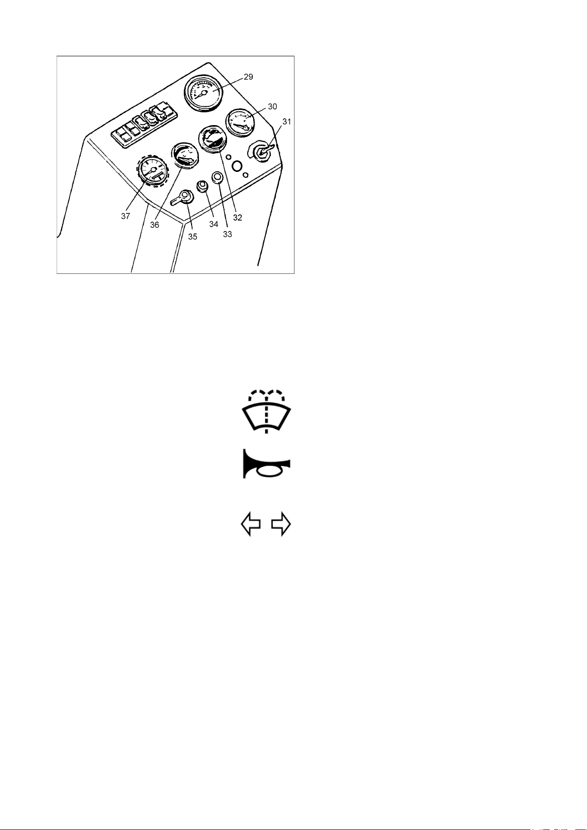
29 Tachometer
The tachometer shows the engine speed.
30 Engine temperature gauge
The temperature gauge shows the temperature of
the engine cooling water. The normal operating
temperature is about 90 oC.
31 Ignition switch
The ignition switch has four positions: OFF-ON-
GL-ST:
OFF = locked
ON = unlocked
GL = glow plugs (sprung)
ST = start (sprung)
32 Hydraulic oil temperature gauge
Shows the temperature of the hydraulic oil.
33 Pushbutton for windscreen washer
When the button is pressed, water is sprayed on to
the windscreen.
34 Pushbutton for signal horn
When the button is pressed, the signal horn
sounds.
35 Direction indicator control
If the knob is moved to the left, the left-hand in-
dicator ashes. If the knob is turned to the right,
the right-hand indicator ashes. The light shines
when the direction indicator is switched on.
N.B. If a direction indicator bulb fails, the light
ashes more quickly!
36 Fuel gauge
Shows the level of fuel in the fuel tank.
37 Running-time meter
Shows the running time of the machine. When the
engine is running, the meter functions.
16
38 Ventilation blower control
The control has three positions: OFF-LOW-HIGH.
39 Cab heating control
The heating control is steplessly adjustable. When
the knob is moved to the left, the heating is swit-
ched off. When the knob is moved to the right, the
maximum heating is obtained.
40 Air nozzles
Used for directing the ow of incoming air. To
obtain
the maximum defroster effect, direct the air ow
towards the windscreen.
Driver’s seat
Turning of the driver’s seat
The driver’s seat can be turned and xed in three
positions: forwards for driving, 60 degrees to the
left for entering and getting out, and backwards for
operating the grab-loader. The seat is released with
the foot pedal 1.
Adjustment of driver’s seat
The seat is moved forwards-backwards with the
lever 2 and the height is adjusted with control 3.
The vertical suspension of the seat is adjusted with
the crank 4. The suspension can be read off on the
scale; the set value shall correspond to the weight
of the driver. The horizontal suspension of the seat
can be locked with the lever 5. The angle of the
seat back can be adjusted with control 6.

17
DRIVING INSTRUCTIONS
Routine check before starting the engine
•Make certain that the accelerator pedal automati-
cally
returns to the idling position.
•Make certain that the drive lever is in the midpo-
sition
and that the winch is disengaged.
Starting of cold engine
Turn the ignition switch to the drive position
(ON). Warning lights for charging and oil pressure
shine. Turn the switch to the ‘glow plug’ position
(GL). When the indicator is extinguished, turn the
switch to the start position (ST).
Make certain that the ignition switch automati-
cally returns to the ‘drive’ position (ON), when the
engine has started.
Don’t run the starter motor continuously for more
than 10 seconds at a time. Repeat the heating with
the glow plugs before the next starting attempt.
Starting of warm engine
No heating with the glow plugs is required for the
starting of a warm engine. Turn the ignition switch
direct to start (ST).
Starting during cold weather
At extremely low temperatures it may prove ne-
cessary to use the glow plugs twice at an interval
of 15 seconds. A full throttle gives the injection
pump the maximum amount of fuel.
Engine heater (option)
During cold weather there may be reason to use an
electric or diesel-powered engine heater to heat the
engine’s cooling water.
Warming up before driving
The engine requires about 4 to 5 minutes’ warming
up, before you can start to drive the machine. Av-
oid engine speeds exceeding 1,500 r.p.m. before
the hydraulic oil has become warm. Drive with the
gearbox in neutral and the trailer drive disenga-
ged.

18
STOPPING OF ENGINE
Allow the diesel engine to slow down to the idling
speed and turn the ignition switch to the position
‘OFF’.
CAUTION! Don’t stop the engine when it is run-
ning at high speed and is warm.
When you leave the machine
Turn off the main switch and take the ignition switch with
you when leaving the machine. In this way you make certain
that all the electrical loads are disconnected and that unaut-
horized persons cannot start the machine.
DRIVING
Driving
N.B. Check that the load cylinder’s lever is in the
upper position, ‘free position’. The gearbox used
in Terri is of preselector type with two speeds. This
means that gear changes can only be made when
Terri is at a standstill.
•Release the brakes
•Move the load cylinder lever to the ‘free position’
•Engage the gears (low/high)
•Select the driving direction with the drive lever
•Increase the engine speed with the accelerator
pedal
Stopping of machine
The machine stops when the accelerator pedal
returns to the idling position or the drive lever is
moved to the mid-position. When the drive lever is
in the mid-position, the hydraulic circuit is closed
and the tracks do not rotate. (See the text about the
brakes.)

19
MAINTENANCE
The preventive maintenance which you yourself
carry out is the most important form of care. It in-
volves lubrication and various checks and adjust-
ments.
Most of these service measures are easy to per-
form and do not require any detailed explanation.
In some cases, however, more detailed instructions
are needed, as described in the following.
DIESEL ENGINE
Running in
Observe the following during the running-in pe-
riod. Change the engine oil and oil lter after 50
hours of service. Never run the machine when it is
cold, but rst let the engine and the hydraulic oil
become warm.
Measures during cold weather
Under winter conditions with temperatures below
0°C observe the following:
· Make certain the cooling water has sufcient
anti-
freeze protection according to the instructions
on
page 22.
· Use oils recommended for winter use, see page
34.
· Fill the fuel tank after nishing your work to
prevent
the formation of condensation water in the tank.
Valve mechanism
Check the valve clearance after every 800 hours
of service. If necessary, adjust the clearance. This
valve adjustment must be carried out by an autho-
rized service centre.
20
Checking of oil level
Check the oil level daily. The oil level shall lie
between the marks on the dipstick (4). Top up if
necessary. See page 34 regarding oil grades.
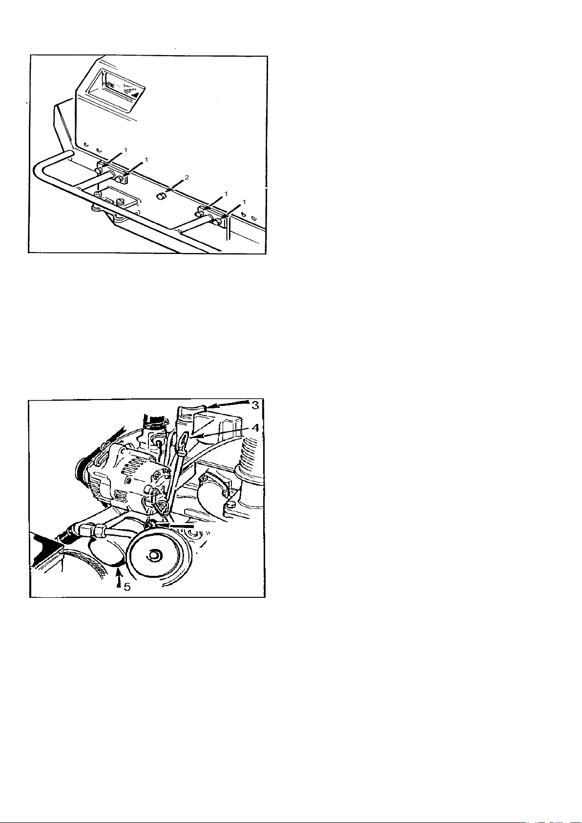
Changing of engine oil
Change the engine oil after every 100 hours of
service.
Run the engine so that it becomes warm.
Slacken the bolts (1) of the undershield by the
bumper, take out the bolt (2) in the middle and
lower down the undershield and withdraw it.
Place a suitable container between the tracks.
Open the drain plug through the hole in the bot-
tom and let the oilrun out.
Replace the drain plug and ll new oil through the
oil lling opening (3). See page 34 regarding the
amount of oil needed.
Check the oil level with the dipstick (4).
Replace the undershield.
Changing of oil lter
Change the oil lter (5) after every 200 hours of
service. Unscrew the old lter, smear the washer
of the new lter with engine oil and tighten the
lter by hand.
Table of contents
Popular Utility Vehicle manuals by other brands


Labrie
Labrie AUTOMIZER FULL EJECT Maintenance manual

Coleman Powersports
Coleman Powersports SK100 Assembly instructions

HAUL MASTER
HAUL MASTER 95419 Assembly and operating instructions

Prime Karts
Prime Karts Racer owner's manual

Floe
Floe 500-95500-00 owner's manual

Columbia
Columbia Journeyman Operator's manual


