Equitel D841 User manual

D841 / D842
D841 / D842D841 / D842
D841 / D842
Technical and installation manual
Technical and installation manualTechnical and installation manual
Technical and installation manual
Video transmission over
optical fibre

This document is the technical reference of D841 and D842 system, a link for 8 channels video
transmission over optical fibre with digital quality.
This document is valid for the following versions of the equipments:
oD841: Version V101
oD842: Version V101
© Equipos De Telecomunicación Optoelectrónicos, S.A.
Zaragoza, Spain, September 2010.
Ed. 1.0
The information included in this manual cannot be copied or reproduced in any way without the previous written authorisation of Equipos de Telecomunicación Optoelectrónicos, S.A.

EQUITEL – Technical manual D841 / D842
iii
September 2010 – Ed.1.0
Technical manual D841 / D842
Index
Chapter 1. Previous steps and precautions........................................................................1
1.1.
Initial inspection ......................................................................................................................1
1.2.
Safety instructions ..................................................................................................................1
Chapter 2 Description ........................................................................................................2
2.1.
General system description ....................................................................................................2
2.2.
D841 description.....................................................................................................................3
2.3.
D842 description.....................................................................................................................4
Chapter 3 Installation.........................................................................................................5
3.1.
Equipments fixing and supply:................................................................................................5
3.2.
Optical connection: .................................................................................................................5
3.3.
Video signals connection........................................................................................................5
Chapter 4 Technical characteristics ...................................................................................6
Chapter 5 Mechanical dimensions .....................................................................................7

EQUITEL - Technical manual D841 / D842 1
September 2010 – Ed.1.0
Chapter 1. Previous steps and precautions
1.1. Initial inspection
Please, check that the contents of the consignment are correct and verify that no element has been
damaged during the transport. In case of mistaken or damaged material, please state an immediate
claim to the transport carrier and notify it immediately to the manufacturer or distributor, either for a
new remittance or for the repair or replacement of the damaged material.
1.2. Safety instructions
All the devices described in this manual have been designed to be properly performed by qualified
technical personnel only. Personnel skilled enough to foresee the possible consequences of
inadequate handling must carry out the installation, setting, maintenance or repair of this equipment.
For a correct and safe use of the provided equipment and in order to achieve the best possible
security conditions, it is essential to follow not only general security procedures but also the special
ones described in this manual.
Never switch on the systems should there be the slightest suspicion of bad functioning.
This may happen as a consequence of damages during storage, transport, etc.
Before any setting or maintenance operations, disconnect the equipment from any power
supply or optical emitter. After electrical disconnection, inside capacitors could remain
loaded for one second.
Active power circuitry could appear when protecting lids or coverings are taken away. Likewise,
unplugged optical connectors must be immediately covered with the corresponding protecting caps.
Should the equipment need to be checked while functioning, remember that maintenance operations
can only be carried out by qualified technical personnel who is aware of the risks of the operation,
both from the electrical and optical point of view.
The security classification of this product is Class III
The modification of the electrical protection elements and the disconnection of the earth terminal
may result in personal injury.
Before the equipment is switched on, make sure that it has been properly grounded (through the
protective conductor of the a.c. power cable) to a socket outlet provided with protective earth contact.
The earth circuit cover of the electrical external connectors must not be used as protective general
earth contact for the equipment.
The optical transmitters could cause safety problems to the personnel in charge of the installation,
test, service or maintenance of the equipment. This is due to the high level of optical power in some
fibre-optic installations and to the fact that light radiation is infrared type (not visible for the human
eye).
As a consequence, never look directly either at the optical output of an optical transmitter, or
at the end of an optical fibre connected to an active optical transmitter. This situation will be
especially dangerous when the inspection takes place with the assistance of light focusing
elements, magnifying glasses, microscopes, etc.
In case these recommendations are not followed, eyes would be exposed to a level of light radiation
that would be higher than the maximum admissible level. This could result in permanent and
irreversible damages in eyes.
The use of controls, adjustments or procedures different from the ones specified here, could cause a
dangerous exposure to radiation.
EQUITEL - Technical manual D841 / D842 2
September 2010 – Ed.1.0
Chapter 2 Description
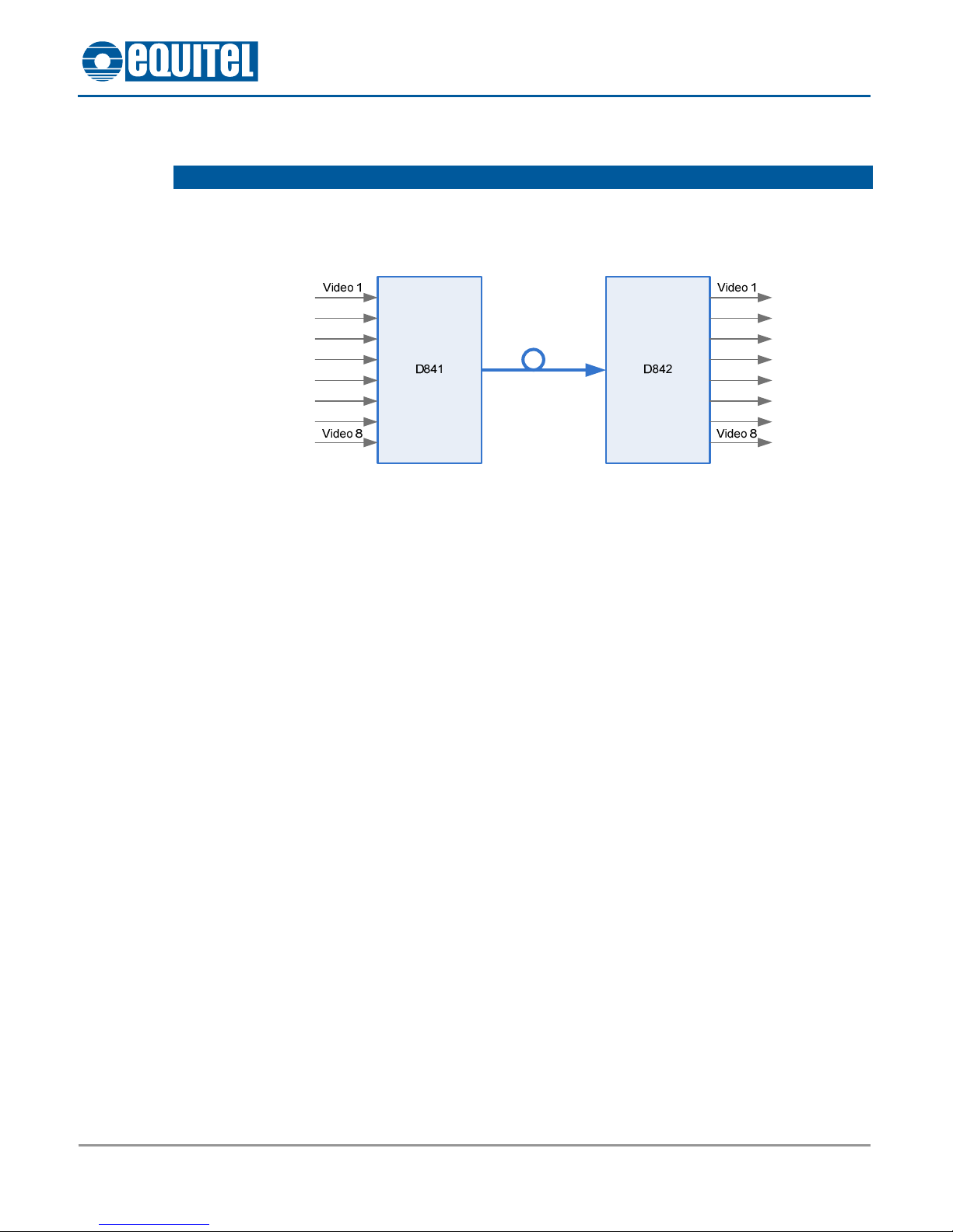
2.1. General system description
D841 and D842 system is the EQUITEL solution for the transmission of up to 8 video channels with
the highest possible quality using only one optical fibre.
Figure 1: D841 / D842 system general diagram
In the D841 unit, the video signals are digitized with a 10 bits resolution, without compression, and
are digitally multiplexed for sending over optical fibre.
In the D842 unit the process is the other way around: the optical signal received is demultiplexed
and the analogue video signals are recovered.
The digitizing process and the signal recovery are made without using any compression algorithm.
This allows a latency of just some hundreds of microseconds (the time between the video signal
input and the reception at D842).
This application is usual in big security installations, tunnels systems control and in any situation
where the transmitted video signal requires an excellent quality and no delays.
Both systems are supplied in stand alone version with 12 Vcc power supply.

EQUITEL - Technical manual D841 / D842 3
September 2010 – Ed.1.0
2.2. D841 description
The following photograph shows the most important parts of this device:
Item
Description
1 Video signal inputs (8 total)
2 Optical fibre output
3 “NV” indicators – Absence of video input
4 “ON” indicator – Equipment on
5 Power supply connector (rear part)
The equipment is powered at 12 Vcc through the rear power terminal. The polarity is indicated in the
cover.
The 8 video inputs have an input impedance of 75 Ωand accept PAL signals, of 1Vpp ± 3dB
1
.
The leds “NV” light when the input signal does not comply with these requirements, or when there is
no signal.
The led “ON” indicates the correct power and internal operation of the equipment.
The output fibre connector is FC/PC for one singlemode fibre 10/125 µ.
1This means that the equipment is capable of compensating input signal amplitude deviations of 3 dB over the 1 Vpp nominal amplitude in both directions.
5
1
3
4
2
Figure 2: Parts of D841
EQUITEL - Technical manual D841 / D842 4
September 2010 – Ed.1.0
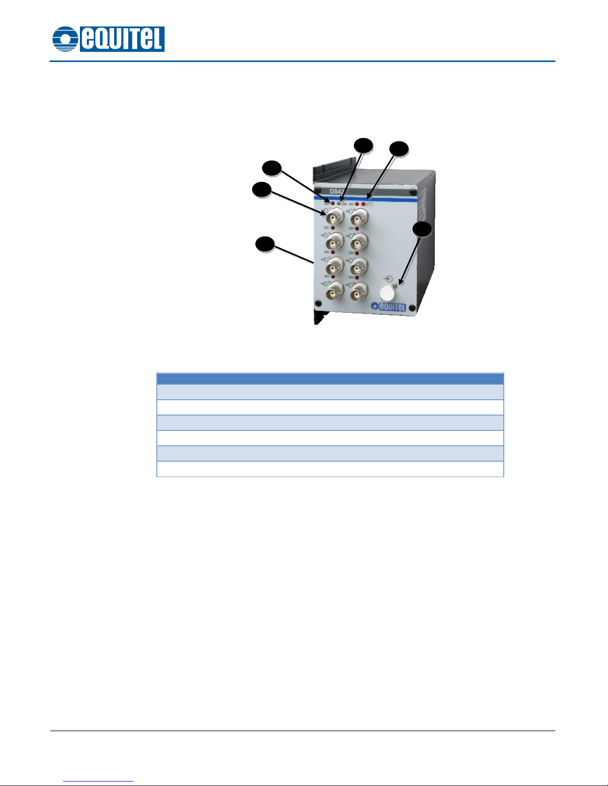
2.3. D842 description
The following photograph shows the most important parts of this device:
Item
Description
1 Video signals outputs (8 total)
2 Fibre optic input
3 “NV” indicators – Absence of video in remote input
4 “APO” indicator – Absence of optical power in fibre input
5 “ON” indicator – Equipment on
6 Power supply connector (rear part)
6
1
3
5
2
4
Figure 3: Parts of D842

EQUITEL - Technical manual D841 / D842 5
September 2010 – Ed.1.0
Chapter 3 Installation
The steps to follow for the correct installation of this system are:
3.1. Equipments fixing and supply:
Fix the equipments in its operating position and connect the rear power terminal to an appropriate
12 Vdc power supply outlet.
The “ON” indicator must turn on.
3.2. Optical connection:
Connect each side of the fibre line to one of the equipments. In order to do that, the following
precautions must be taken into account. This is very important:
The optical output connectors must be thoroughly cleaned. Use an optical-cleaning paper or gauze
dampened with ethylic or isopropilic alcohol.
Introduce the fibre jumpers in the optical connectors after removing the protective cover. Both tabs
must be aligned and adequately screwed.
We insist that it is very important to follow these indications. The introduction of a non-cleaned
optical connector in the equipment may end up in serious damages that could make necessary it to
be repaired.
Likewise, the introduction of strange mechanical elements in the optical connector may result in
irreparable damages in the internal connector.
Once both systems are connected, the indicator “APO” in D842 must remain switched off, indicating
that the signal from D841 is received correctly.
3.3. Video signals connection
Connect the video sources to the D841 inputs and the receivers to the D842 outputs.
The corresponding “NV” leds, both in D841 and D842, must switch off.

EQUITEL - Technical manual D841 / D842 6
September 2010 – Ed.1.0
Chapter 4 Technical characteristics
General features
Type of transmission Digital video (10 bit) without compression
Video signals 8
Optical parameters
Optical emitter (D841) DFB laser
Optical receiver (D842) PIN-TIA
Wavelength 1310 / 1550 nm
Optical power (D841) ≥-4 dBm
Sensitivity (D842) ≤-24 dBm
Video parameters
Amplitude (D841) 1 Vpp ±3 dB
Wavelength 1310 / 1550 nm
Optical power (D841) ≥-4 dBm
Output amplitude (D842) 1 Vpp
Impedance 75 Ω
Differential gain < 2 % peak to peak
Differential phase < 2 º peak to peak
Bandwidth > 5,8 MHz
SNR weighed > 67 dB
Power paramenters
Voltage 12 Vcc ± 5%
Consumption (D841) < 14 W
Consumption (D842) < 12 W
Environmental
Operating temperature
range
-40 ºC to 74 ºC
Humidity 0 a 95% without condensing
Notes:
•Typical values, as production average.
•Actual values are given in the test sheet. These values are measured according to the test
procedure for this device.

EQUITEL - Technical manual D841 / D842 7
September 2010 – Ed.1.0
Chapter 5 Mechanical dimensions
Figure 4: Mechanical dimensions D841 / D842
This manual suits for next models
1
Table of contents


 user manual")


