TESTO 6381 User manual

testo 6381 Ethernet · differential pressure transmitter
testo 6610 · Probes
P2A software · Parameterizing, adjusting and analyzing
software
Instruction manual Volume 1
1.800.561.8187info@Testo-Direct.ca www.Testo-Direct.ca
All manuals and user guides at all-guides.com
all-guides.com

1 Safety and the environment
3
Pos: 1 /TD/Übersc hriften/MUF/Sicher heit und Umwelt @ 3\mod_1234 793958627_79.doc @ 26223 @ 1
1 Safety and the environment
Pos: 2 /TD/Sic herheit und Umwelt/Sicher heit gewährleisten/ MUF 63xx/Elektrisc he Gefahren vermeiden @ 3\ mod_1234794609299_79. doc @ 26280 @ 5
Avoiding electrical hazards
> Never use the instrument and connected probes to measure on
or near live parts!
> Damaged mains cables must only be replaced by authorized
personnel.
> Only have the transmitter wired and connected by authorized
personnel with the voltage disconnected.
> You must always comply with the regulations applicable in your
country for opening and repairing electrical equipment.
Pos: 3 /TD/Sic herheit und Umwelt/Sicher heit gewährleisten/ MUF 63xx/Personen- und Sac hschäden vermeiden @ 3\ mod_1234794744768_79 .doc @ 26299 @ 5
Avoiding personal injury and damage to equipment
> Installation, setting and calibration work must only be carried
out by qualified and authorized personnel!
> Only open the instrument when this is expressly described in
the instruction manual for installation, maintenance or repair
purposes.
> Observe the permissible storage, transport and operating
temperature.
Pos: 4 /TD/Sic herheit und Umwelt/Si cherheit gewährlei sten/Nicht mit Lös ungsmitteln lag ern @ 0\mod_117569237517 9_79.doc @ 583 @
> Do not store the product together with solvents. Do not use any
desiccants.
Pos: 5 /TD/Sic herheit und Umwelt/Sicher heit gewährleisten/ MUF 63xx/Bei War tungM UFnic ht zur Regelung verwende n @ 3\mod_1234794852377_7 9.doc @ 26318 @
> Do not use the instrument for control purposes at the same time
as operating or servicing the transmitter.
Pos: 6 /TD/Sic herheit und Umwelt/Si cherheit gewähr leisten/Produkt besti mmungsgemäß ver wenden @ 0\mod_117378126 1848_79.doc @ 386 @
> Only operate the product properly, for its intended purpose and
within the parameters specified in the technical data. Do not
use any force.
Pos: 7 /TD/Sic herheit und Umwelt/Sicher heit gewährleisten/ Nur beschriebene War tungsarbeiten durc hführen @ 0\mod_1175692705195 _79.doc @ 601 @
> Carry out only the maintenance and repair work on this
instrument that is described in the documentation. Follow the
prescribed steps exactly. Use only original spare parts from
Testo.
Pos: 8 /TD/Sic herheit und Umwelt/Sicher heit gewährleisten/ MUF 63xx/Fachpersonal @ 3\ mod_1234794940409_7 9.doc @ 26337 @
Any additional work must only be carried out by authorized
personnel. Otherwise testo will not accept any responsibility for the
proper functioning of the instrument after repair and for the validity
of certifications.
1.800.561.8187info@Testo-Direct.ca www.Testo-Direct.ca
All manuals and user guides at all-guides.com

2 About this document
4
Pos: 9 /TD/Übersc hriften/MUF/Umwelt sc hützen @ 3\mod_1234858 757571_79.doc @ 26363 @ 5
Protecting the environment
Pos: 10 /TD/Sic herheit und Umwelt/ Umwelt schützen/Pr odukt entsorgen @ 0\ mod_1173780307072_ 79.doc @ 357 @
> At the end of its useful life, send the product to the separate
collection for electric and electronic devices (observe local
regulations) or return the product to Testo for disposal.
Pos: 11 /TD/Übersc hriften/MUF/Zu diese m Dokument @ 3\mod_12347939 91331_79.doc @ 26242 @ 1
2 About this document
Pos: 12 /TD/Sic herheit und Umwelt/Zu diese m Dokument/Verwendun g (Standard) @ 0\mod_117377 5068554_79.doc @ 337 @ 5
Use
> Please read this documentation through carefully and
familiarize yourself with the product before putting it to use. Pay
particular attention to the safety instructions and warning advice
in order to prevent injuries and damage to the products.
> Keep this document to hand so that you can refer to it when
necessary.
> Hand this documentation on to any subsequent users of the
product.
Pos: 13 /TD/Sic herheit und Umwelt/Zu die sem Dokument/Symbole und Sc hreibkonventione n/Warnhinweis W ARNUNG@ 2\ mod_1207646966234_7 9.doc @ 14398 @
WARNING Indicates potential serious injuries
Pos: 14 /TD/Sic herheit und Umwelt/Zu diese m Dokument/Symbole und Sc hreibkonventione n/Warnhinweis VORSIC HT@ 2\ mod_1207651416515_79. doc @ 14416 @
CAUTION indicates potential minor injuries
Pos: 15 /TD/Sic herheit und Umwelt/Zu diese m Dokument/Symbole und Sc hreibkonv. Soft ware[ Standard] @ 0\mod_11902 03332543_79.doc @ 4883 @ 5
Symbols and writing standards
Representa-
tion Explanation
Note: Basic or further information.
1. ...
2. ... Action: more steps, the sequence must be
followed.
> ... Action: a step or an optional step.
- ... Result of an action.
Menu Elements of the program interface.
[OK] Buttons of the program interface.
... | ... Functions/paths within a menu.
“...” Example entries
Pos:16 /TD/--- Seitenwechsel--- @ 0\mod_11737744306 01_0.doc @ 283 @
1.800.561.8187info@Testo-Direct.ca www.Testo-Direct.ca
All manuals and user guides at all-guides.com

3 Contents
5
Pos: 17 /TD/Übersc hriften/MUF/Inhal t @ 3\mod_1234794019831_ 79.doc @ 26261 @ 1
3 Contents
1Safety and the environment....................................................................3
2About this document...............................................................................4
3Contents...................................................................................................5
4Transmitter...............................................................................................7
4.1. Specifications ..................................................................................7
4.1.1. Functions and use ...........................................................................................7
4.1.2. Scope of delivery.............................................................................................7
4.1.3. Accessories .....................................................................................................8
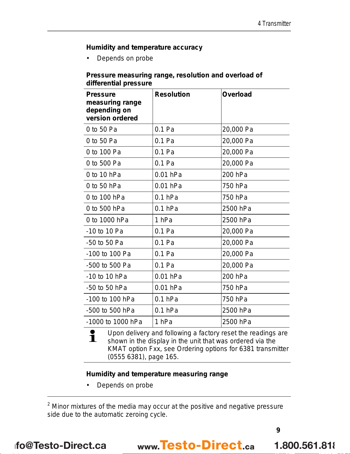
4.1.4. Technical data .................................................................................................8
4.1.5. Dimensions....................................................................................................12
4.2. Product description........................................................................13
4.2.1. At a glance.....................................................................................................13
4.2.2. Usable probes................................................................................................14
4.2.3. Display and keypad........................................................................................15
4.2.4. Service interface............................................................................................15
4.2.5. Relay board (option) ......................................................................................15
4.2.6. Analog outputs...............................................................................................16
4.2.7. Parameters....................................................................................................16
4.2.8. Scaling .........................................................................................................17
4.2.9. Alarm handling...............................................................................................20
4.3. Commissioning..............................................................................21
4.3.1. Inserting Ethernet module (order no. 0554 6656)...........................................21
4.3.2. Assembling the instrument.............................................................................23
4.3.2.1. Wall mounting (for testo 6611, 6613, 6614, 6615, 6617 probes).......23
4.3.2.2. Duct mounting (for testo 6612 probes)..............................................24
4.3.3. Connecting the instrument.............................................................................25
4.3.3.1. Overview of terminals........................................................................27
4.3.3.2. Connecting voltage supply and analog outputs.................................28
4.3.3.3. Connecting the relay outputs ............................................................29
4.3.3.4. Plug-in connection option..................................................................32
4.3.3.5. Creating the PE/earthing terminal.....................................................33
4.3.3.6. Setting the Ethernet module..............................................................34
4.3.3.7. Closing the instrument ......................................................................36
4.3.4. Ethernet communication................................................................................37
4.3.4.1. Types of operation............................................................................37
4.3.4.2. Mains connection..............................................................................37
4.3.4.3. LED status displays ..........................................................................38
4.3.4.4. testo 6381 as Saveris subscriber......................................................38
4.3.4.5. Integration into customer's Ethernet system......................................39
4.3.4.6. Adjusting the instrument....................................................................49
4.3.4.7. Overview: Adjustment keys and test contacts...................................50
1.800.561.8187info@Testo-Direct.ca www.Testo-Direct.ca
All manuals and user guides at all-guides.com

3 Contents
6
4.3.4.8. 1-point adjustment (offset - humidity/temperature)............................51
4.3.4.9. 2-point adjustment (humidity/temperature)........................................53
4.3.4.10. Analog output adjustment ..........................................................55
4.3.4.11. n-point adjustment (pressure)....................................................56
4.3.4.12. High-humidity adjustment for testo 6614....................................57
4.3.4.13. Self adjustment of testo 6615 trace humidity probe....................58
4.4. Operation......................................................................................60
4.4.1. Relationship between user menu and mini-DIN socket is active....................60
4.4.2. Key cover ......................................................................................................60
4.4.3. Password protection......................................................................................61
4.4.4. Structure of user menu..................................................................................61
4.4.5. Overview of the testo 6381 user menu ..........................................................63
4.4.6. The individual main menus............................................................................66
4.4.6.1. Editing main menu of channel 1........................................................66
4.4.6.2. Editing Main Menu Channel 2 (if this option is available) ..................66
4.4.6.3. Editing Main Menu Channel 3 (if this option is available) ..................67
4.4.6.4. Editing Main Menu Alarm..................................................................67
4.4.6.5. Editing Main Menu Settings ..............................................................69
4.4.6.6. Editing Main Menu Analysis..............................................................73
4.4.6.7. Editing Message main menu.............................................................75
4.4.6.8. Calling up Main Menu Ident ..............................................................76
4.4.6.9. Editing Main Menu Adjust.................................................................76
4.4.6.10. Editing Reset main menu...........................................................79
4.5. Status, warning and error messages ............................................79
4.5.1. Status messages...........................................................................................80
4.5.2. Warning messages........................................................................................81
4.5.3. Transmitter error messages...........................................................................83
4.5.4. Handling alarm messages .............................................................................84
4.5.5. Namur fault conditions...................................................................................86
4.6. Maintenance and cleaning............................................................87
4.6.1. Maintaining the instrument.............................................................................87
4.6.2. Cleaning the instrument.................................................................................87
Pos:18 /TD/--- Seitenwechsel--- @ 0\mod_11737744306 01_0.doc @ 283 @
1.800.561.8187info@Testo-Direct.ca www.Testo-Direct.ca
All manuals and user guides at all-guides.com

4 Transmitter
7
Pos: 19 /TD/Übersc hriften/MUF/1 Messu mformer @ 3\mod_123425840 1060_79.doc @ 23894 @ 1
4 Transmitter
Pos: 20 /TD/Übersc hriften/MUF/1.1/2. 1/3.1 Leistungsbe schreibung @ 3\mod_123425 8595211_79.doc @ 23951 @ 2
4.1. Specifications
Pos: 21 /TD/Leis tungsbeschreibung/V erwendung/MUF63 xx/MUF 638x Ethernet @ 3\mod_12344 43770405_79.doc @ 25020 @ 3
4.1.1. Functions and use
The testo 6381 transmitter with Ethernet module is used together
with the plug-in, adjusted probes from the testo 6610 family.
Please refer to volume 2, testo 6610 probes, page 93 for
information about commissioning, operating and maintaining the
testo 6610 probe.
The testo 6381 transmitter is suitable for the following applications
with Ethernet networking, amongst others:
• Clean rooms
• Test benches
• Drying processes
• Filling processes
• Painting systems
• Monitoring flow velocities or volumetric flow rates in air
conditioning systems
In addition to the signal transmission of the readings to a control
unit via analog outputs, the measurement data can simultaneously
be recorded, documented and visualized via Ethernet.
Furthermore, it is possible to issue an alarm for those responsible
for the process, if necessary.
Pos: 22 /TD/Leis tungsbeschreibung/Li eferumfang/MUF 63 xx/MUF 63xx Ethernet @ 3\mod_ 1234447308472_79. doc @ 25117 @ 3
4.1.2. Scope of delivery
The scope of delivery of the testo 6381 transmitter includes the
following:
• Key cover
• Rear panel bracket
• Ethernet module
• Instruction manual
• Calibration report
• CD-ROM with operating instructions (PDF), configuration files
for Ethernet module and P2A update (this can only be used in
conjunction with the P2A software, which has to be ordered
separately).
1.800.561.8187info@Testo-Direct.ca www.Testo-Direct.ca
All manuals and user guides at all-guides.com
all-guides.com

4 Transmitter
8
Pos: 23 /TD/Leis tungsbeschreibung/Li eferumfang/MUF 63 xx/Zubehör Übersicht 63 8x @ 3\mod_1234448071530 _79.doc @ 25136 @ 3
4.1.3. Accessories
The following accessories are available for the testo 6381
transmitter, amongst others:
• Protection caps for probes
• Mains unit
• P2A software (parameterizing, adjusting and analyzing
software)
• Assembly accessories
Information about accessories and their order numbers can
be found in volume 2, Accessories and spare parts or on
the website at www.testo.com.
Pos: 24 /TD/Leis tungsbeschreibung/ Technische Daten/ MUF63 xx/MUF 638x Ethernet @ 3\ mod_1234448296123_79. doc @ 25156 @ 3555555555555555 555555555
4.1.4. Technical data
Parameters
• Differential pressure
• Humidity (various variables and units)
• Temperature (°C/°F)
Differential pressure accuracy
The specifications are only valid if the positive pressure is
applied at the positive pressure connection.
• 0.5 % of measuring range, additional 0.3 Pa intrinsic error1
• TK slope drift = 0.03 % of measuring range per degree Kelvin of
deviation from nominal temperature 22 °C
• TK zeroing drift= 0 %, as zeroing with solenoid valve2
1Measuring uncertainty in accordance with GUM: ±0.8 % of measuring range
final value ±0.3 Pa.
GUM (Guide to the Expression of Uncertainty in Measurement): ISO guideline for determining the
measuring uncertainty in order to render global measurement results comparable.
The following uncertainties are used during the inquiry:
• Hysteresis
• Linearity
• Reproducibility
• Adjustment area/factory calibration
• Test location
1.800.561.8187info@Testo-Direct.ca www.Testo-Direct.ca
All manuals and user guides at all-guides.com

4 Transmitter
9
Humidity and temperature accuracy
• Depends on probe
Pressure measuring range, resolution and overload of
differential pressure
Pressure
measuring range
depending on
version ordered
Resolution Overload
0 to 50 Pa 0.1 Pa 20,000 Pa
0 to 100 Pa 0.1 Pa 20,000 Pa
0 to 500 Pa 0.1 Pa 20,000 Pa
0 to 10 hPa 0.01 hPa 200 hPa
0 to 50 hPa 0.01 hPa 750 hPa
0 to 100 hPa 0.1 hPa 750 hPa
0 to 500 hPa 0.1 hPa 2500 hPa
0 to 1000 hPa 1 hPa 2500 hPa
-10 to 10 Pa 0.1 Pa 20,000 Pa
-50 to 50 Pa 0.1 Pa 20,000 Pa
-100 to 100 Pa 0.1 Pa 20,000 Pa
-500 to 500 Pa 0.1 Pa 20,000 Pa
-10 to 10 hPa 0.01 hPa 200 hPa
-50 to 50 hPa 0.01 hPa 750 hPa
-100 to 100 hPa 0.1 hPa 750 hPa
-500 to 500 hPa 0.1 hPa 2500 hPa
-1000 to 1000 hPa 1 hPa 2500 hPa
Upon delivery and following a factory reset the readings are
shown in the display in the unit that was ordered via the
KMAT option Fxx, see Ordering options for 6381 transmitter
(0555 6381), page 165.
Humidity and temperature measuring range
• Depends on probe
2Minor mixtures of the media may occur at the positive and negative pressure
side due to the automatic zeroing cycle.
1.800.561.8187info@Testo-Direct.ca www.Testo-Direct.ca
All manuals and user guides at all-guides.com

4 Transmitter
10
Humidity and temperature resolution
• 0.1 % RH or 0.01 °C/0.01 °F
Meas. cycle
• 1/sec
Interface
• Mini-DIN for P2A software (parameterizing and adjusting
software) and handheld testo 400/650
Voltage supply
• 4-wire (separate signal and supply lines): 20 to 30 V AC/DC,
300 mA power consumption
Maximum load
• 4-wire: 500 Ω(power output)
Maximal load
• 4-wire: 10 kΩ(voltage output)
Analog output
• 0 to 1 V ± 1.5 mV (4-wire) or
• 0 to 5 V ± 7.5 mV (4-wire) or
• 0 to 10 V ± 15 mV (4-wire) or
• 0 to 20 mA ± 0.03 mA (4-wire) or
1.800.561.8187info@Testo-Direct.ca www.Testo-Direct.ca
All manuals and user guides at all-guides.com

4 Transmitter
11
• 4 to 20 mA ± 0.03 mA (4-wire)
Resolution of analog output
• 12 bit
Relay
• 4 relays, 250 V AC/DC, 3 A (optional)
Display
• 2-line LCD with plain text line (optional)
Operating temperature
• -5 to 50 °C/23 to 122 °F
Storage temperature
• -20 to 60 °C/-4 to +140 °F
Process temperature
• -20 to 65 °C/-4 to 149 °F
Oper. humidity
• 0 to 90 % RH
Housing, weight
• Metal: 1.960 kg
• Ethernet module: 0.610 kg
Protection class
• IP 65 only if the transmitter iswired properly (closed cable
entries), Ethernet connector, Harting PushPull connector and
humidity probe are inserted and/or sealing plugs are inserted.
Directives, standards and tests
• EC Directive: 2004/108/EC
• DIN 14644-4
• EN 61000-6-2 interference immunity
• EN 61000-6-3 interference emission
• EN 61326-1+A1+A2
1.800.561.8187info@Testo-Direct.ca www.Testo-Direct.ca
All manuals and user guides at all-guides.com

4 Transmitter
12
Ethernet module
• Interface:
◦1 x mini-DIN
◦1 x RJ45 (Ethernet 10 BaseT/100 BaseTX)
• LED:
2 x green
Warranty
• Duration: 2 years
• Warranty conditions: see website www.testo.com/warranty
Pos: 25 /TD/Leis tungsbeschreibung/ Technische Daten/ MUF63 xx/MUF 63xx Abmessungen @ 3\ mod_1234450671494_79. doc @ 25194 @ 3
4.1.5. Dimensions
Dimensions in mm a b
with M20 cable couplings 144 147
With NPT cable coupling 144 144
With M plug-in connection 143
Pos: 26 /TD/Übersc hriften/MUF/1.2/2. 2 Produktbeschrei bung @ 3\mod_1234258723551 _79.doc @ 24008 @ 2
1.800.561.8187info@Testo-Direct.ca www.Testo-Direct.ca
All manuals and user guides at all-guides.com
all-guides.com

4 Transmitter
13
4.2. Product description
Pos: 27 /TD/Produk tbeschreibung/ Übersicht/MUF 63xx/Auf einen Blick MUF 638 xEt hernet @ 3\mod_1234772 621147_79.doc @ 25612 @ 3
4.2.1. At a glance
1 Keys (only with optional display)
2 Service flap screw connection
(self-locking, 2 pcs.)
3 Display (optional)
4 Service flap
5 Negative pressure connection
6 Positive pressure connection,
marked with a red washer
7 M 16 x 1.5 screw connection*,
e.g. analog outputs
8 M 16 x 1.5 screw connection*,
e.g. voltage supply
9 Earthing/PE connection
10 M 20 x 1.5 screw connection*,
e.g. R3 and R4 relays
11 Eyelet for measuring point panel
12 M 20 x 1.5 screw connection*,
e.g. R1 and R2 relays
13 Probe connector (testo 6610)
14 Upper part of housing
* Alternatively, NPT cable
couplings or M plug-in
connections are available
A Ethernet module
1 DIP switch
2 Ethernet port
3 LED: LAN connection status
4 LED: Supply
1.800.561.8187info@Testo-Direct.ca www.Testo-Direct.ca
All manuals and user guides at all-guides.com

4 Transmitter
14
5 Housing screws
6 Socket for probe connector
7 Hole for fastening to rear panel
bracket (M3 x 6 screw)
8 Plastic bracket for assembly on
rear panel
Pos: 28 /TD/Produk tbeschreibung/ Übersicht/MUF 63xx/Ver wendbare Fühler 638x @ 3\mod_12 34773201901_79.doc @ 25631 @ 3
4.2.2. Usable probes
The testo 6381 transmitter can be used with the following probes:
Probes Article no. Characteristic
testo 6611 0555 6610-L11 Wall probe version; accuracy to ±1 % RH;
temperature range -20 to +70 °C/-4 to +158 °F,
sensor plugged in
testo 6612 0555 6610-L12 Duct probe version; accuracy to ±1 % RH;
temperature range -30 to +150 °C/
-22 to +302 °F, sensor soldered
testo 6613 0555 6610-L13 Cable probe version; accuracy to ±1 % RH;
temperature range -40 to +180 °C/
-40 to +356 °F, sensor soldered
testo 6614 0555 6610-L14 Heated cable probe version; accuracy to ±1.0 %
RH; temperature range -40 to +180 °C/
-40 to +356 °F, sensor soldered
1.800.561.8187info@Testo-Direct.ca www.Testo-Direct.ca
All manuals and user guides at all-guides.com

4 Transmitter
15
Probes Article no. Characteristic
testo 6615 0555 6610-L15 Trace humidity cable probe version; accuracy
±1 K at 0 °Ctd/+32 °Ftd; temperature range
-40 to 120 °C/-40 to +248 °F, sensor soldered
testo 6617 0555 6610-L17 Cable with cover electrode monitoring probe
version; accuracy to ± 1.2 % RH; temperature
range -40 to 180 °C/
-40 to +356 °F, sensor soldered
Pos: 29 /TD/Produk tbeschreibung/ Übersicht/MUF 63xx/Dis play und Tastatur @ 3\ mod_1234773965059_79.doc @ 25650 @ 3
4.2.3. Display and keypad
The display option allows operation of the testo 6381 transmitter via
the display and four keys.
The LCD display consists of two 7-segment lines for displaying
readings and units and of an information line (for status messages,
for example).
The brightness and contrast of the display and the background
lighting (permanent or off) can be changed via the user menu or the
P2A software.
Pos: 30 /TD/Übersc hriften/MUF/1.2. xSer viceschnitts telle @ 3\mod_123730689165 4_79.doc @ 29795 @ 3
4.2.4. Service interface
Pos: 31 /TD/Produk tbeschreibung/ Übersicht/MUF 63xx/Ser viceschnittstel le 638x @ 3\mod_12347740929 11_79.doc @ 25669 @
The parameterizing socket (mini-DIN) is located behind the service
flap as an interface to the P2A software or Testo handheld
instrument (testo 400/testo 650).
Pos: 32 /TD/Produk tbeschreibung/ Übersicht/MUF 63xx/Rel aisplatine (Option) @ 3\mod_1234774 184843_79.doc @ 25688 @ 3
4.2.5. Relay board (option)
This has a floating switch capacity of 250 V AC/3 A. The switching
limits and hysteresis as well as the function as relay for the
collective alarm can be set via the display or the P2A software.
Further features include:
• Function of changeover contacts (NC/NO contacts) freely
selectable
• 12 terminals for a total of 4 relays.
If no relays are available, settings for monitoring limit values
or alarms can still be controlled via the display. The alarm
status will be shown on the display.
Only have the transmitter wired and connected by
authorized personnel with the voltage disconnected.
1.800.561.8187info@Testo-Direct.ca www.Testo-Direct.ca
All manuals and user guides at all-guides.com

4 Transmitter
16
Pos: 33 /TD/Produk tbeschreibung/ Übersicht/MUF 63xx/Ana logausgänge 638x @ 3\mod_1 234774341528_79.doc @ 25707 @ 3
4.2.6. Analog outputs
As analog outputs, the testo 6381 has either
• 1 or optionally 3 current outputs of 0 to 20 mA (4-wire)/4 to
20 mA (4-wire) or
• 1 or optionally 3 voltage outputs of 0 to 1 V/0 to 5 V/0 to 10 V
(4-wire).
The transmitter can be ordered with three analog outputs as an
option.
The optional three channels are galvanically isolated.
Pos: 34 /TD/Produk tbeschreibung/ Übersicht/MUF 63xx/Messgr ößen 638x @ 4\mod_1248354 361572_79.doc @ 46349 @ 3
4.2.7. Parameters
The following parameters are displayed
• Differential pressure in Pa, hPa, kPa, mbar, bar, mmH2O,
kg/cm2, PSI, inch HG, inch H2O
• Volumetric flow rate3in m3/h, l/min, Nm3/h, Nl/min
• Flow4in m/s, ft/min
• Relative humidity in % RH (technical)
• Relative humidity in % WMO* (calculation according to the
WMO standard)
• Degree of humidity in g/kg and gr/lb
• Absolute humidity in g/m³ and gr/ft³
• Water content in ppm (vol) and % vol
• Psychrometer temperature in °Ctw and °Ftw
• Enthalpy in kJ/kg and BTU/lb
• Water vapour partial pressure in hPa and H2O
• Dewpoint temperature in °Ctd and °Ftd
• Standardized dewpoint in °CtdA , standardized at atmospheric
pressure (1013 hPa); precondition: Absolute process pressure.
* It is possible that condensation appears as of a displayed
humidity starting from 70 % and is shown on the display. This
unit is used in meteorology, amongst others. When calculating
3Calculated
4To prevent fluctuating flow rate values at the zero point (depressurized), the
flow rate values are only calculated as of differential pressures > 0.2 Pa or
> 0.1 % of the respective measuring range (whichever is the greater). With
smaller differential pressures, the flow rate value remains at 0.00 m/s.
1.800.561.8187info@Testo-Direct.ca www.Testo-Direct.ca
All manuals and user guides at all-guides.com

4 Transmitter
17
the relative humidity the Magnus coefficient with undercooled
water is used in accordance with WMO.
Calculated humidity variables correspond to the medium of
air. With other gases/gas compositions, deviations may
occur, e.g. with the enthalpy.
• Dewpoint of H2O2mixture in °Ctm and °Ftm
• Temperature °C and °F
Pos: 35 /TD/Produk tbeschreibung/ Übersicht/MUF 63xx/Ska lierung @ 3\mod_123477540 6989_79.doc @ 25783 @ 3
4.2.8. Scaling
There are three types of min./max. values:
1 The measuring range: The maximum sensor performance is in
this range. Values outside of the measuring range are displayed
via messages, for example. Measuring range, see table
(below).
2 Standard scaling: The output signals are assigned to this
measuring range as standard:
◦during delivery if no entries are made in the order code
◦after exchanging the unit, the measuring range recorded in
the instrument is applied as standard.
The transmitter even retains its scaling with the voltage
disconnected.
Measuring range, see table (below).
3 The maximum settings for the manual scaling
◦The maximum limits can be calculated as follows:
X = difference between MIN. and MAX. value of the
standard scaling
(Max. value of standard) + (50 % of X)
(Min. value of standard) - (50 % of X)
◦It is thus possible to scale beyond the measuring range, e.g.
for the adjustment of the scaling limits to standard values of
a PLC.
With the alarm definition, however, the physical measuring
range limits are decisive.
Pos: 36 /TD/Produk tbeschreibung/ Übersicht/MUF 63xx/Tabe lle Skalierung MUF 638 x@ 3\ mod_1236343950039_79. doc @ 27502 @
1.800.561.8187info@Testo-Direct.ca www.Testo-Direct.ca
All manuals and user guides at all-guides.com
all-guides.com

4 Transmitter
18
Measuring
range/standard
scaling
Maximum scaling
0 to 50 Pa -5 to 15 Pa
0 to 50 Pa -25 to 75 Pa
0 to 100 Pa -50 to 150 Pa
0 to 500 Pa -250 to 750 Pa
0 to 10 hPa -5 to 15 hPa
0 to 50 hPa -25 to 75 hPa
0 to 100 hPa -50 to 150 hPa
0 to 500 hPa -250 to 750 hPa
0 to 1000 hPa 500 to 1500 hPa
-10 to 10 Pa -20 to 20 Pa
-50 to 50 Pa -100 to 100 Pa
-100 to 100 Pa -200 to 200 Pa
-500 to 500 Pa -1000 to 1000 Pa
-10 to 10 hPa -20 to 20 hPa
-50 to 50 hPa -100 to 100 hPa
-100 to 100 hPa -200 to 200 hPa
-500 to 500 hPa -1000 to 1000 hPa
-1000 to 1000 hPa -2000 to 2000 hPa
Pos: 37 /TD/Produk tbeschreibung/ Übersicht/MUF 63xx/Tabe lle Skalierung Fühler 638x @ 3\mod_123477 5771238_79.doc @ 25802 @
Physical
measuring range
at 1013 hPa
Standard scaling of
transmitter
measuring range
Parameter Unit Probes
MIN MAX MIN MAX
°C 6611 -20 +70 -20 +70
°F 6611 -4 +158 -4 +158
°C 6612 -30 +150 -30 +150
°F 6612 -22 +302 -22 +302
Temperature
°C 6613,
6614,
6617
-40 +180 -40 +180
1.800.561.8187info@Testo-Direct.ca www.Testo-Direct.ca
All manuals and user guides at all-guides.com

4 Transmitter
19
Physical
measuring range
at 1013 hPa
Standard scaling of
transmitter
measuring range
°F 6613,
6614,
6617
-40 +356 -40 +356
°C 6615 -40 +120 -40 +120
°F 6615 -40 +248 -40 +248
°Ctd 6611 -20 +70 -80 +100
°Ftd 6611 -4 +158 -112 +212
°Ctd 6612,
6613,
6614,
6617
-20 +100 -80 +100
°Ftd 6612,
6613,
6614,
6617
-4 +212 -112 +212
°Ctd 6615 -60 +30 -80 +100
Dewpoint
°Ftd 6615 -76 +86 -112 +212
g/m3all
probes 0 600 0 2000
Absolute
humidity gr/ft3all
probes 0 250 0 800
relative humidity % RH all
probes 0 100 0 100
WMO relative
humidity % RH 0 100 0 100
°Ctm -20 +100 -20 +100
Mixture dewpoint
(H2O2) °Ftm -4 +212 -4 +212
g/kg all
probes 0 13300 0 9500
Degree of
humidity gr/lb all
probes 0 93000 0 66500
kJ/kg -40 99999 -40 8000Enthalpy BTU/lb -18 43000 -18 3500
Psychrometer °Ctw -40 100 -40 180
1.800.561.8187info@Testo-Direct.ca www.Testo-Direct.ca
All manuals and user guides at all-guides.com

4 Transmitter
20
Physical
measuring range
at 1013 hPa
Standard scaling of
transmitter
measuring range
temperature °Ftw -58 210 -40 356
ppm
(vol)
H2O
0 99999 0 99999
Water content
% vol 0 100 0 100
hPa 0 1000 0 7000
Water vapour
partial pressure inchH2O 0 400 0 2800
Pos: 38 /TD/Produk tbeschreibung/ Übersicht/MUF 63xx/Alar mbehandlung @ 3\mod_12 34776787635_79.doc @ 25821 @ 3
4.2.9. Alarm handling
For upper and lower alarm limits, individual alarms as well as
collective alarms can be specified. If the collective alarm function is
activated, an alarm is triggered as soon as the alarm limit of an
alarm is exceeded, if this alarm is assigned to the collective alarm.
The testo 6381 monitors limit values with the help of relays. If a
reading is outside the limit values, a relay to be specified by the
user is switched.
If the reading reverts to more than a specified hysteresis below or
above the limit value, the alarm is cancelled.
In addition, information about the occurrence of error/status
messages can be provided by means of a collective alarm relay,
see Status, warning and error messages, page 79
If multiple alarm messages are activated at the same time,
the last alarm is shown. If the alarm is cancelled again, the
previous messages are no longer shown.
Pos: 39 /TD/Übersc hriften/MUF/1.3/2. 3 Inbetriebnahme @ 3\ mod_1234258805768_79. doc @ 24027 @ 2
1.800.561.8187info@Testo-Direct.ca www.Testo-Direct.ca
All manuals and user guides at all-guides.com

4 Transmitter
21
4.3. Commissioning
Pos: 40 /TD/Erst e Schritte/MUF 63xx/E thernet-spezifi sch/Ethernetmodul einse tzen 638x @ 3\mod_12348746 03926_79.doc @ 26424 @ 3
4.3.1. Inserting Ethernet module (order no. 0554 6656)
The Ethernet module can be ordered retroactively as an accessory.
It can easily be installed in the testo 6381 transmitter.
✓ The probe connector must be disconnected.
1. Loosen screw connection (1) of service flap and open the flap.
2. Loosen and remove housing screws (2).
3. Remove upper part of housing (3) and place on a clean surface.
1.800.561.8187info@Testo-Direct.ca www.Testo-Direct.ca
All manuals and user guides at all-guides.com
Other manuals for 6381
4
Table of contents
Other TESTO Transmitter manuals

TESTO
TESTO 6781 User manual

TESTO
TESTO 6631 User manual

TESTO
TESTO 6651 User manual

TESTO
TESTO 6681 Profibus User manual

TESTO
TESTO 6682 Installation instructions

TESTO
TESTO 6383 User manual

TESTO
TESTO 6740 User manual

TESTO
TESTO 6383 User manual

TESTO
TESTO 6681 Profibus User manual

TESTO
TESTO 6682 User manual