ERBA ELite 5 User manual
Erba Lachema s.r.o., Karásek 2219/1d, 621 00 Brno, CZ
ELite 5
Hematology Analyzer
USER MANUAL
INS00068

Page 2 of 159
Introduction
This user manual is intended to give detailed information for end users of the ‘ELite 5’ optical
hematology analyzer.
All information contained herein is the intellectual property of Erba Lachema s.r.o. and should
not be used or reproduced without prior agreement of Erba Lachema s.r.o., the
manufacturer.
This manual was written with the intention to give the most precise and up-to-date, detailed
description of operation and use of the analyzer for laboratory purposes.
Despite careful revision and multiple grammar and content control, mistakes can still be
present in this manual. Erba Lachema may from time to time issue errata, or a new revision
of the manual. Would you find things unclear, please contact your service engineer for
assistance.
Descriptions contained herein are relevant to ‘ELite 5’, software versions (latest available at
the publication of the manual):
High Level SW version: 1.5.2105.0
Low Level SW version: 1.5.2105.0
Low Level boot version 2.0
Firmware: 2.78 (1208)
PIC SW: 2.1
Laser SW: 3.5
TCU SW: 3.42

Page 3 of 159
Warranty
THIS WARRANTY IS EXCLUSIVE AND IS IN LIEU OF ALL OTHER WARRANTIES,
EXPRESSED OR IMPLIED, INCLUDING WARRANTIES OF MERCHANTABILITY OR
FITNESS FOR ANY PARTICULAR PURPOSE.
Exemptions
Erba Lachema’s obligation or liability under this warranty does not include any transportation
or other charges or liability for direct, indirect or consequential damages or delay resulting
from the improper use or application of the product or the use of parts or accessories not
approved by Erba Lachema or repairs by people other than Erba Lachema authorized
personnel.
This warranty shall not extend to:
•Any Erba Lachema product which has been subjected to misuse, negligence or
accident.
•Any Erba Lachema product from which Erba Lachema’s original serial number tag or
product identification markings have been altered or removed.
•Any product of any other manufacturer.

Content
Page 4 of 159
Table of Contents
1
For Your Safety ........................................................................................................ 10
1.1 Who Should Use This Manual ....................................................................................... 10
1.2 Spe ial symbols used in this Manual............................................................................. 10
1.3 General Pre autions .................................................................................................... 10
1.4 Environmental Fa tors ................................................................................................. 11
1.5 Ele tri al Requirements ............................................................................................... 12
1.6 Spa e Requirements .................................................................................................... 12
1.7 Weight Requirements .................................................................................................. 14
1.8 Waste Disposal ............................................................................................................ 15
1.9 Known Limitations ....................................................................................................... 15
1.10 Emergen y Situations .................................................................................................. 15
2
Product Support ....................................................................................................... 16
3
Installation .............................................................................................................. 17
3.1 Pa kage ontents ......................................................................................................... 17
3.1.1
The ‘ELite 5’ Analyzer Package ....................................................................................................... 1
3.1.2
The Autosampler Package ............................................................................................................. 1
3.1.3
Small Sample Package (optional) ................................................................................................... 1
3.2 Conne ting the reagents .............................................................................................. 18
3.3 Power onne tion ........................................................................................................ 18
3.4 Conne tions to the peripherals .................................................................................... 18
3.5 Environmental onditions ............................................................................................ 18
3.6 Visual inspe tion ......................................................................................................... 19
3.7 Moving to the sele ted lo ation ................................................................................... 19
3.8 Removing the safety ard from the shear valve ............................................................ 19
3.9 Conne ting the Autosampler ........................................................................................ 20
3.10 Conne ting the reagents .............................................................................................. 20
4
General O er iew and Principles of Operation .......................................................... 21
4.1 General Overview ........................................................................................................ 21
4.1.1
Measured Parameters ................................................................................................................... 21
4.1.2
Approved Reagents and Control Materials .................................................................................... 22
4.1.3
Original Erba Lachema Reagents ................................................................................................... 22
4.2 Prin iples of Operation ................................................................................................ 24
4.2.1
Volumetric Impedance Method ..................................................................................................... 24
4.2.2
Photometric Light Absorbance Method ........................................................................................ 24

Content
Page 5 of 159
4.2.3
Optical Light Scatter and Diffraction Method ................................................................................ 25
Inside the ‘ELite 5’ Analyzer .................................................................................................... 28
4.2.4
Front Panel ..................................................................................................................................... 28
4.2.5
Back Panel ...................................................................................................................................... 28
4.2.6
Left Side Assembly ......................................................................................................................... 30
4.2.
Right Side Assembly ....................................................................................................................... 31
4.2.8
Front Assembly .............................................................................................................................. 32
4.3 Small Sample Mode (SSM) – optional ........................................................................... 32
5
User Interface .......................................................................................................... 34
5.1 Using the Tou h S reen ................................................................................................ 34
5.2 Using the ‘Start’ Button ............................................................................................... 34
5.3 Using an External Mouse ............................................................................................. 34
5.4 Using an External Keyboard ......................................................................................... 35
5.5 Using the On-S reen Virtual Keypads ........................................................................... 35
5.6 Using the Graphi al User Interfa e ............................................................................... 37
5.6.1
Quick Links ..................................................................................................................................... 3
5.6.2
Interactive Display Area ................................................................................................................. 3
5.6.3
Status Display ................................................................................................................................. 38
5.6.4
Entering Information ..................................................................................................................... 38
5.7 The Menu System ........................................................................................................ 38
5. .1
Primary Menu Items ...................................................................................................................... 38
5. .2
Starting a Manual Single Tube Measurement ............................................................................... 38
5. .3
Start Automated Measurements ................................................................................................... 39
5. .4
Access the Database ...................................................................................................................... 39
5. .5
Initiate Printing .............................................................................................................................. 39
5. .6
Main Menu .................................................................................................................................... 40
5. .
Autosampler (AS) Control Panel .................................................................................................... 40
5. .8
Adjust the Time and Date .............................................................................................................. 40
5. .9
Open the Warning Panel ................................................................................................................ 40
5. .10
Menu tree ...................................................................................................................................... 41
5. .11
Safety Access Codes ....................................................................................................................... 43
5. .12
SSM Menu Add-ons ....................................................................................................................... 43
6
Start Up and Shut Down of ‘ELite 5’ .......................................................................... 45
6.1 Start Up and Shut Down Overview ............................................................................... 45
6.2 Starting Up the ‘ELite 5’ Analyzer ................................................................................. 45
6.2.1
Visual Inspection ............................................................................................................................ 45
6.2.2
Power Up the ‘ELite 5’ Analyzer ..................................................................................................... 45
6.2.3
Start Up the User Interface ............................................................................................................ 46
6.2.4
User Login ...................................................................................................................................... 4
6.2.5
Pneumatic System Start and Blank Measurement ........................................................................ 4
6.3 Exiting the ‘ELite 5’ Analyzer ........................................................................................ 48
6.3.1
Log Off ............................................................................................................................................ 48
6.3.2
Shut Down...................................................................................................................................... 49

Content
Page 6 of 159
6.3.3
Prepare for Shipment .................................................................................................................... 49
6.3.4
Emergency Shut Down ................................................................................................................... 52
6.3.5
Repackaging the ‘ELite 5’ Analyzer ................................................................................................ 53
7
Sample Measurement .............................................................................................. 55
7.1 Sample Types Supported by the ‘ELite 5’ ...................................................................... 55
.1.1
Supported Sample Tube Types ...................................................................................................... 55
.1.2
Sampling Depth .............................................................................................................................. 55
.1.3
Open or Closed Sample Tubes ....................................................................................................... 56
.1.4
Sample Collection and Handling .................................................................................................... 56
7.2 Sample Types and Modes ............................................................................................ 57
7.3 Sample Identifi ation ................................................................................................... 57
7.4 Running Samples ......................................................................................................... 58
.4.1
Manual Mode ................................................................................................................................ 58
.4.2
Prediluted mode ............................................................................................................................ 61
.4.3
Automatic Mode ............................................................................................................................ 62
7.5 Result Display .............................................................................................................. 72
7.6 Printing Reports........................................................................................................... 72
7.7 The Measurement Pro ess ........................................................................................... 72
8
Result Interpretation ................................................................................................ 74
8.1 The Result S reen ........................................................................................................ 74
8.2 Sample Identifi ation Information ................................................................................ 74
8.3 Parameter Information ................................................................................................ 75
8.3.1
Scatter Diagrams and Histograms .................................................................................................. 6
8.3.2
Warnings ........................................................................................................................................
9
Database Functions .................................................................................................. 85
9.1 Database Overview ...................................................................................................... 85
9.2 S rolling the Database View ......................................................................................... 86
9.3 Sorting Database Information ...................................................................................... 87
9.4 Manual Sele tion of Database Re ords ......................................................................... 87
9.5 Automati Sele tion of Database Re ords .................................................................... 88
9.6 Viewing Detailed Results ............................................................................................. 88
9.7 Statisti s ...................................................................................................................... 88
9.8 Managing Database Re ords ........................................................................................ 88
9.8.1
Select By ......................................................................................................................................... 89
9.8.2
Importing ....................................................................................................................................... 90
9.8.3
Export ............................................................................................................................................. 91
9.8.4
Send to LIS...................................................................................................................................... 91
9.8.5
Save Tab File .................................................................................................................................. 91
9.8.6
Save Raw Data ............................................................................................................................... 92
9.8.
Delete ............................................................................................................................................. 92

Content
Page of 159
10
Calibration ........................................................................................................... 93
10.1 Calibrating the ‘ELite 5’ ................................................................................................ 94
10.1.1
View Calibrations ........................................................................................................................... 95
10.2 SSM Calibration ........................................................................................................... 96
11
Quality Control ..................................................................................................... 97
11.1 Set QC Referen e ......................................................................................................... 97
11.2 QC Measure................................................................................................................. 99
11.3 View QC Referen es ..................................................................................................... 99
11.4 View QC Data .............................................................................................................. 99
11.5 View QC Diagrams ....................................................................................................... 99
11.6 View X-B Data............................................................................................................. 100
11.7 View X-B diagrams ...................................................................................................... 101
12
Patients ............................................................................................................ 102
13
Settings ............................................................................................................... 104
13.1 Customize Settings ..................................................................................................... 104
13.2 Laboratory Settings..................................................................................................... 105
13.3 External Devi es ......................................................................................................... 106
13.4 System Settings .......................................................................................................... 107
13.5 Units .......................................................................................................................... 108
13.6 Printer Settings ........................................................................................................... 109
13.7 Profile Limits Settings ................................................................................................. 110
13.8 X-B Settings ................................................................................................................ 111
13.9 User Settings .............................................................................................................. 112
13.10 Date and Time Adjustment ...................................................................................... 113
14
Instrument Diagnostics ........................................................................................ 114
14.1 Self Test of the Analyzer ............................................................................................. 115
14.2 Daily Log .................................................................................................................... 117
14.3 Reagent Status ........................................................................................................... 117
14.4 Statisti s ..................................................................................................................... 118
14.5 Information ................................................................................................................ 118
15
Maintenance ....................................................................................................... 120
15.1 Opening the Front Panel ............................................................................................. 120
15.1.1
Closing the Front Panel ................................................................................................................ 121
15.1.2
Removing the Side Panels ............................................................................................................ 121

Content
Page 8 of 159
15.1.3
User Maintainable Parts of the Analyzer ..................................................................................... 121
15.2 Maintenan e Programs of the Analyzer ....................................................................... 122
15.2.1
Cleaning the Shear Valve ............................................................................................................. 123
15.2.2
Cleaning the Washing Head ......................................................................................................... 12
15.2.3
Cleaning the Measuring Chambers (Hard Cleaning) .................................................................... 128
15.2.4
Daily Cleaning .............................................................................................................................. 128
15.2.5
Special Cleaning Procedure .......................................................................................................... 128
15.2.6
Replacing Reagents ...................................................................................................................... 129
15.2.
Disposal of Reagent Containers ................................................................................................... 130
16
Reagent Locking .................................................................................................. 131
17
The Daily-Routine ................................................................................................ 132
18
Troubleshooting .................................................................................................. 134
18.1 Software error messages ............................................................................................ 134
18.2 Pneumati error messages .......................................................................................... 134
18.3 Me hani al Problems .................................................................................................. 135
18.4 Sample Rotor (SR) Failures .......................................................................................... 135
18.4.1
SR Gives Grinding Noise And / Or SW Displays SR Error Messages ............................................. 135
18.4.2
SR Error Appears During Initialization Process: ........................................................................... 136
18.4.3
The SR Does Not Turn Into the Analyzer Even With Open Front Panel ....................................... 136
18.5 Needle Me hani s, Verti al Motor (Mvert) Problems ................................................... 136
18.5.1
The Needle Carriage Keeps Dropping Back (Down) At Initialization ............................................ 136
18.6 Shear Valve (SV) Related Errors ................................................................................... 136
18.6.1
SV Error at the First Startup ......................................................................................................... 136
18.6.2
Grinding Noise after SV Cleaning, (after SV Reinstallation) ......................................................... 136
18.6.3
SV Leakage ................................................................................................................................... 136
18.7 Dilutor Errors .............................................................................................................. 137
18.8 Priming Problems ....................................................................................................... 137
18.8.1
The Analyzer Would Not Prime Liquids ....................................................................................... 13
18.9 Ele troni s Related Problems ...................................................................................... 137
18.9.1
No Image on Display, No Backlight .............................................................................................. 13
18.9.2
Touch Sensitive Surface Not Working .......................................................................................... 13
18.9.3
Touch (Click) Is Inaccurate ........................................................................................................... 13
18.9.4
The Cursor Seems To Be Moving With Good Ratios, But In a Smaller Area ................................ 13
18.10 The Analyzer Does Not Power On ............................................................................ 137
18.11 I2 Errors Displayed At Startup ................................................................................ 137
18.12 Measurement results related problems ................................................................... 138
18.12.1
Fluctuating PLT background values .............................................................................................. 138
18.12.2
Long, smeared population ........................................................................................................... 138
19
Accessories .......................................................................................................... 139
20
Appendices .......................................................................................................... 140
20.1 Reagent Consumption ................................................................................................ 140

Content
Page 9 of 159
20.2 Display Range ............................................................................................................. 141
20.3 Printed Report Formats .............................................................................................. 142
20.4 Spe ifi ations ............................................................................................................. 144
20.4.1
Measured Parameters ................................................................................................................. 144
20.4.2
Technical Data .............................................................................................................................. 145
20.4.3
Performance Data ........................................................................................................................ 148
20.4.4
Reagent System ........................................................................................................................... 151
20.4.5
Tab File Format ............................................................................................................................ 152
20.5 Fluidi System............................................................................................................. 153
20.6 Summary of Cleaning Produ ts and Pro edures for Elite Hematology Analyzers ........... 154
21
Known Problems .................................................................................................. 155
22
Index ................................................................................................................... 156
23
Contact ................................................................................................................ 158
24
Appendix- package inserts for reagents and cleaning solutions ............................ 159

ELite 5, User Manual
Page 10 of 159
1 For Your Safety
1.1 Who Should Use This Manual
This User Manual is intended for clinical laboratory professionals using the ‘ELite 5’
automated hematology analyzer. The Manual includes information about the operation and
user interface of the ‘ELite 5’ analyzer.
It also contains basic steps necessary to perform the setup procedures to adapt the
operation of the analyzer to the requirements of your laboratory.
This manual also describes daily routine maintenance requirements to keep your analyzer
functioning properly.
1.2 Special symbols used in this Manual
Label
Meaning Explanation
Biohazard Blood samples and analyzer waste are potentially
infectious materials.
Corrosive Reagents may cause corrosion or skin irritation.
Warning General warning of possible hazard conditions.
Sharp needle warning The sampling needle may be a hazard to the operator.
1.3 General Precautions
The analyzer weighs 35kg (~77lbs).Please do not attempt to move it alone. The
analyzer should always be moved by two persons holding the analyzers by its sides
in an upright position.
Always use safe lifting procedures when lifting the analyzer.
Make sure to retain the original packaging material for safe transportation and
storage in the future.
To prepare the analyzer for shipping, storage or extended periods of inactivity,
please drain the reagents and repackage the ‘ELite 5’ in its original packaging. Do
not expose the ‘ELite 5’ to direct sunlight, extreme temperature or humidity (>80%).
The analyzer operates with chemically and biologically active reagents. Physical
contact with these reagents should be avoided. Please read reagent descriptions
carefully for possible emergency actions.

ELite 5, User Manual
Page 11 of 159
To ensure reliable operation and reliable results:
•Only human blood samples should be analyzed
•Only original Erba Lachema reagents should be used
•Required maintenance (user and service level) should be performed as
recommended in this Manual
•Only Erba Lachema certified service personnel should perform service
actions
•Only original Erba Lachema service materials and spare parts should be
used
Original reagents and service materials and spare parts are available from Erba
Lachema.
Only Erba Lachema certified service personnel that have successfully completed
the ‘Erba Lachema ELite 5 Service Training program are qualified to service the
‘ELite 5’ analyzer.
Before operating the ‘ELite 5’ analyzer, all operators should complete the ‘Erba
Lachema ELite 5 Operator Training’ program. This program is offered by Erba
Lachema or by Erba Lachema certified service personnel.
Replacement materials or spare parts (tubes, valves, etc.) which might have been in
contact with human blood or reagents should be handled as a potentially
biologically hazardous and chemically dangerous material. All applicable laws and
regulations must be observed in the handling and disposal of these materials.
The ‘ELite 5’ is designed for laboratory operation. Mobile operation is not supported.
Operate ‘ELite 5’ within the ambient temperature range described in section 1.4.
The IVD equipment complies with the emission and immunity requirements
described in relevant part of the IEC 61326 series.
This equipment has been designed and tested to CISPR 11 Class A. In a domestic
environment it may cause radio interference, in which case, you may need to take
measures to reduce the interference.
Electromagnetic environment should be evaluated prior to operation of the device.
This analyzer contains electronic components. Please handle electronic
waste adhering to local or federal regulations.
1.4 Environmental Factors
Operate the ‘ELite 5’ analyzer at the ambient temperature within the range of 15-30°C
(59-86 °F) and a relative humidity range of 10% - 80%. The optimum operating temperature
is 25°C (~77°F).
Avoid exposing the ‘ELite 5’ analyzer to direct sunlight or to extreme high or low
temperatures. If the ‘ELite 5’ analyzer was subjected to extreme temperatures during
shipment or storage, the analyzer must be placed for at least one hour in a room whose
temperature is within the operational range before installation or use.
Reagents should be stored within the temperature range of 15-30°C (59-86 °F).
The analyzer should be placed in a well-ventilated location.

ELite 5, User Manual
Page 12 of 159
Operation at an altitude above 3000 meters (9800 ft) is not recommended.
1.5 Electrical Requirements
The analyzer should only be operated from a wall outlet meeting these power input
requirements:
•100-127VAC/200-240VAC; 47Hz to 63Hz
•Power Consumption: maximum 400 VA
Please ensure that the wall outlet is also capable of supplying the power consumption of any
additional devices (such as a printer).
Only the power cord supplied with the instrument should be used. Avoid using extension
cords. The ‘ELite 5’ analyzer comes with a power cord appropriate for your power system.
Proper use of the appropriate power cord assures adequate grounding of the system. If the
power network is not reliable, contact your representative for options such as the installation
of an external UPS module.
Failure to properly ground the ‘ELite 5’ bypasses important safety features
and may result in electrical hazard.
The instrument should not be placed near potentially interfering devices capable of emitting
radio frequencies (e.g. radio or television transmitters/receivers, radars, centrifuges, X-ray
devices, fans, etc.).
This analyzer is designed to be safe for transient voltages to INSTALLATION CATEGORY II
and POLLUTION DEGREE 2.
1.6 Space Requirements
It is important to install the instrument in a suitable location. A poor location can adversely
affect its performance.
Select a well-ventilated location near a power source and close to a suitable drain.
Place the unit on a clean, level surface. Leave at least 0.5 m (18 inches) space on both sides
and above the instrument to access pneumatics. A minimum of 0.2 m (8 inches) must be
maintained between the rear panel and the wall to allow for heat dissipation and tube
clearance.
Ensure there is enough clearance in front of the ‘ELite 5’ analyzer to open the front panel.
Allow enough space if you want to use optional external keyboard, mouse or bar code
reader.
Your selected location should allow placement of the reagents in an unobtrusive location
below the laboratory bench that the instrument is placed on, or on the same surface.
Placement below the laboratory bench also allows for storage of a spare set of reagents.
Never place the reagents above the ‘ELite 5’ analyzer.
See Chyba! Nenalezen zdroj odkazů.and Chyba! Nenalezen zdroj odkazů.for more
information about proper analyzer location and clearance.
ELite 5, User Manual
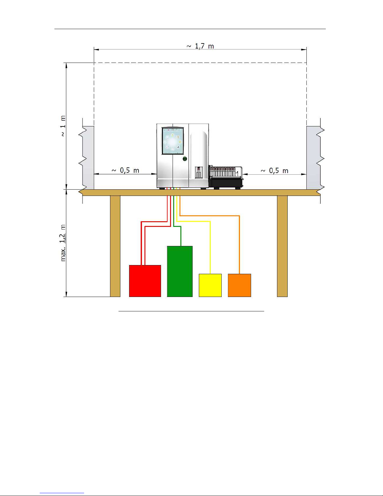
Page 13 of 159
Figure 1. ELite 5 with Autosampler Space Requirements

ELite 5, User Manual
Page 14 of 159
Figure 2. ELite 5 Without Autosampler Space Requirements
1.7 Weight Requirements
The ‘ELite 5’ analyzer weighs 35 Kg (77 lb) without the Autosampler. The ‘ELite 5’ with
optional Autosampler weighs 47Kg (104 lb). Adding an external keyboard, printer etc. can
bring the total weight up to 60 Kg (132 lb). If you decide to store the reagents on the same
surface, then the combined weight can reach 100 Kg (220 lb).
Please select a table, laboratory shelf, or other location which can support the weight of the
‘ELite 5’ with accessories and is free from vibration.
ELite 5, User Manual
Page 15 of 159
To allow reliable operation and to provide a safe working environment, make
sure that the table supporting the unit is stable enough to carry the weight of
the instrument and accessories.
1.8 Waste Disposal
‘ELite 5’ analyzer waste contains human blood and reagents that are chemically and
biologically active, and should be considered to be a potential infection and biohazard threat.
Safe laboratory practices must be followed including the use of personal protective when
operating the ‘ELite 5’ and handling blood, reagents, and waste.
1.9 Known Limitations
The ‘ELite 5’ is not intended for analysis of animal blood samples. Anti-coagulated and
homogenized human blood samples must be free from contamination.
Blood samples must be analyzed within 12 hours of venipuncture.
1.10 Emergency Situations
Always follow all applicable laws and regulations with regard to emergency situations.
If the ‘ELite 5’ needs to be powered off due to an emergency situation (like fire, thunderstorm
etc.), follow the procedures in chapter 6.3.4.
In case of fire, do not use water to extinguish the fire unless the ‘ELite 5’ is
disconnected from the electrical network!

ELite 5, User Manual
Page 16 of 159
2 Product Support
Your sales representative is trained and qualified to answer questions about applications and
the operation of the ‘ELite 5’ analyzer. If you have additional questions regarding the ‘ELite
5’, please ask for manufacturer support through your sales representative.
Erba Lachema makes every effort to provide excellent support and up to date information
and services regarding the ‘ELite 5’ analyzer. Software updates and application documents
are available on the Erba Lachema web site at http://www.erbamannheim.com.

ELite 5, User Manual
Page 1 of 159
3 Installation
Your Erba Lachema certified service engineer will perform the initial installation of the ‘ELite
5’ analyzer and train you and selected laboratory personnel on the proper use and
maintenance of the analyzer. The analyzer should only be operated by properly trained
personnel. You’ll also be explained about necessary maintenance actions.
3.1 Package contents
3.1.1 The ‘ELite 5’ Analyzer Package
After opening the ‘ELite 5’ analyzer packaging, you will find an accessory box. The analyzer
is in a plastic bag in between cushioning protective material. After opening the bag, remove
the desiccant packs. The package should contain the following items:
•‘ELite 5’ analyzer
•Accessories box on top of the analyzer, containing:
•Power cord
•User Manual (this document)
•Sample tube adapter for the individual sample unit (1 pc)
•Reagent tube kit (in a plastic bag, with special caps)
•Plastic waste container
•Cardboard box for the waste container
•“Preparing for shipment” tube kit
•‘ELite 5’ analyzer Final Check Report
Please inform your Sales Representative if any item is missing or damaged. Retain the
original ‘ELite 5’ analyzer packaging for future transportation and storage.
3.1.2 The Autosampler Package
The Autosampler is an optional unit that attaches to the ELite 5. If the optional Autosampler
unit was ordered, package should contain the following items:
•Autosampler unit
•Sample tray
•Sample racks -10 pieces
•Autosampler Final Check Report
Please inform your sales representative if any item is missing or damaged. Retain the
original Autosampler packaging for future transportation and storage.
3.1.3 Small Sample Package (optional)
•SSM Micro dilutor front-left frame rail assembly
•Ribbon cable #1 with connectors for the SSM micro dilutor
•SSM valve assembly with connected Tygon tubing
•“T” fitting with attached 3 cm Tygon tube
•4-way ribbon cable #2 with connectors for the SSM valve assembly
•Pre-dilution chamber plus pre-dilution chamber holder assembly with rubber chamber
protector
•SSM sample rotor plate
•2 pcs of 3x10 hex screws with washers (used for mounting SSM pre-dilution chamber holder)
•Adhesive cable holder, plastic adhesive tube holder and 2 pcs of plastic tube holders
ELite 5, User Manual
Page 18 of 159
•Silicon edge protectors and cable guide tool
3.2 Connecting the reagents
The ‘ELite 5’ is capable to aspirate reagents from 1.2m (~4’). (Measured from the bottom of
the reagent container to the table level where the ‘ELite 5’ is installed.)
You will use 3 input reagents and the 2 waste-output. Select a location close to a suitable
drain. The waste container should be periodically emptied.
You can place the reagent below or on the same level where the ‘ELite 5’ is installed. Do not
place the reagents to a higher location than the bottom of the ‘ELite 5’, because in case of
any tubing problem, valve error etc. the reagent can spill out.
3.3 Power connection
The analyzer should only be operated from a wall out
let meeting general
specifications of power input requirements: 100-127VAC/200-240VAC; 47Hz
to 63Hz
Power Consumption: maximum 400 VA
If the power network is not reliable, contact your representative for options
(e.g. installation of an external UPS module).
Only the power cord supplied with the instrument should be used. Avoid
using extension cords.
Please check the power consumption of the additional devices (printer) as well.
3.4 Connections to the peripherals
If you plan to connect any external devices (printer, host-computer etc.) to ‘ELite 5’ then prior
the installation please check the possible cable paths. If it is necessary then make all the
preparations (cable-channels, cable-binders, drilling trough tables, walls etc.) before the
installation starts.
Although the Windows
®
XP
®
Embedded operating system can recognize several peripheral
devices please prepare the installation material provided by the vendor of the device.
3.5 Environmental conditions
The ‘
ELite
5’ is designed for laboratory operation.
Mobile operation is not
supported. Operate ‘ELite 5’ at the ambient temperature within the range of
15-30°C (59-98 °F) and maximum relative humidity of 80%. The optimum
operating temperature is 25°C. Reagents should be stored at a temperature
range of 15-30°C. The ‘ELite 5’ operates properly up to 3000 meters above
sea-level.
Do not place the reagent containers to a higher position than ‘ELite 5’. This
is to avoid unintentional spilling of reagents. The vertical distance between
the reagent container and ‘ELite 5’ must not be more than 120 centimeter.
The instrument should be placed in a well-ventilated location. The instrument should not be
placed near potentially interfering devices capable of emitting radio frequencies (e.g. radio or
television transmitters/receivers, radars, centrifuge, X-ray devices, fans, etc.).

ELite 5, User Manual
Page 19 of 159
Operation at an altitude over 3000 meters (9000 ft) is not recommended.
3.6 Visual inspection
To ensure correct operation, and to check that the instrument has been delivered to you
without any damage, please check the following before starting the unit for the first time:
‘ELite 5’:
•The front panel should have no cracks;
•The screen should have no cracks;
•No visible dents or bumps on instrument housing (front, side rear, top cover);
•Open the front panel of the unit:
oThe front panel is easy to open and close (see section 15.1);
oInspect that the syringes are not cracked;
oCheck if the shear valve has the safety card installed;
oCheck if there are no fluid inside the tubing;
oCheck if there are no salt build-ups inside the tubing.
Autosampler:
•No visible dents or bumps on the housing of the Autosampler;
•The transparent cover opens and closes smoothly;
•The sample-tray and the racks have no visible damage.
3.7 Moving to the selected location
Check the presence of all necessary connections.
Move the ‘ELite 5’ to the selected location.
If it is hard to access the back of the ‘ELite 5’ after it is in the final location then connect the
reagent tubes to the ‘ELite 5’ but not to the reagent containers. (For details see chapter 3.2)
Be sure that the main switch (right next to the power connector) is in off position.
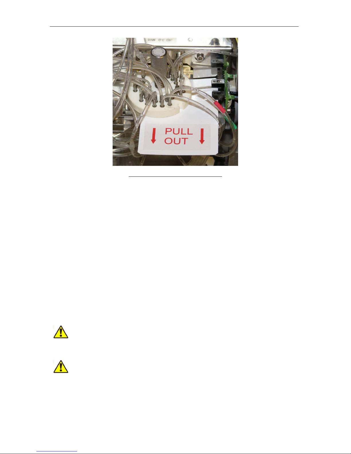
3.8 Removing the safety card from the shear valve
In order to prevent the damage of the shear valve during transportation a protective plastic
card is placed between the ceramic disks of the shear valve. Before using the ’ELite 5’
instrument, this card must be removed.
Please perform the following steps:
•Open the cover of the equipment
•Locate the white plastic card in shear valve
•Pull out the card
•Check and tighten the locking screw of the shear valve if necessary
ELite 5, User Manual
Page 20 of 159
Figure 3. Shear Valve with plastics card
3.9 Connecting the Autosampler
If the optional Autosampler unit also purchased then:
•Remove the secondary cover-plate from the right-side cover-plate of the ‘ELite 5’;
•Check that the connection surface is clean and there are no blocking objects (like
hanging, swinging cables);
•Push the Autosampler into the ‘ELite 5’ until the clamps are locked.
3.10 Connecting the reagents
If it was not done beforehand than:
•Connect the reagent tubes to the ‘ELite 5’:
oUse the supplied connecting tubes and special bottle caps;
oBe sure that the color on each tube, cap and connector in the back of the
instrument match.
•Connect the reagent containers to the reagent tubes.
The analyzer operates with chemically and biologically active reagents.
Direct (skin) contact with these reagents should be avoided. Please read
reagent descriptions carefully for possible emergency actions. Only original
reagents are usable with ‘ELite 5’, available from Erba Lachema.
Place the reagent containers near the instrument, to an accessible location.
Do not place the containers to a higher position than ‘ELite 5’. This is to
avoid unintentional spilling of reagents.
Table of contents
Other ERBA Laboratory Equipment manuals

Popular Laboratory Equipment manuals by other brands


Velp Scientifica
Velp Scientifica AREX 5 instruction manual

PSI
PSI AlgaeTron Manual and user guide

PerkinElmer
PerkinElmer OilExpress System user guide

Excelitas Technologies
Excelitas Technologies X-Cite TURBO quick start guide

Quorum
Quorum Q150T Fitting instructions

Tuttnauer
Tuttnauer 5050 Operation & maintenance manual


