Dynatron 900+ User manual


Dynatron 900+™
ii
CAUTION: Federal law restricts this device to sale by or on the order of a
physician, chiropractor, physical therapist, or dentist, licensed by the law of the
state in which said person practices, to use or order the use of the device.
IMPORTANT: Traction Therapy must be prescribed by a licensed practitioner
following an appropriate physical examination and diagnostic analysis. Before
treating a patient with the Dynatron 900+™Traction System, see the
“Contraindications, Warnings, and Precautions” in this manual. A copy of the
manual should be kept with the device at all times.
DANGER - Explosion Hazard: Do not use in the presence of flammable gas or
anesthetics.
Do not use theTraction System near X-ray or Diathermy devices. These devices
may emit high frequency noise that could affect the operation of the Dynatron
900+™Traction device.
INDICATIONS FOR USE
Dynatron 900+Traction System
The Dynatron 900+ Traction system is intended for medical purposes for use in conjunction with
traction accessories such as belts and harnesses to exert therapeutic pulling forces on the
patient’s body primarily for the cervical and lumbar areas.
Dynatron 900+™Operator and Service Manual
Copyright 2010
Dynatronics Corporation
7030 Park Centre Drive
Salt Lake City, UT 84121
(800) 874-6251 - (801) 568-7000
www.dynatronics.com
ALL RIGHTS RESERVED
REV. 12-10_00
INVENTORY: 5D00040

Dynatron 900+™
iii
TABLE OFCONTENTS
SECTION I
INTRODUCTION ..................................................................................................................1
BEFOREYOU TREAT A PATIENT ..................................................................................................................... 1
INSTALLATION AND FEATURES...................................................................................................................... 2
UNPACKING................................................................................................................................................... 2
STANDARD COMPONENTS ............................................................................................................................ 2
OPTIONAL ACCESSORIES............................................................................................................................. 2
SECTION II
PHYSICAL FEATURES ..........................................................................................................3
DESCRIPTION OF PHYSICAL FEATURES........................................................................................................ 4
SECTION III
OPERATING INSTRUCTIONS..................................................................................................8
DETAILED TREATMENT SETUP....................................................................................................................... 9
ADDITIONAL TRACTION MODES –QUICK SETUP INSTRUCTIONS ............................................................. 11
SPECIAL USAGE PROCEDURES................................................................................................................. 12
SECTION IV
CONTRAINDICATIONS,WARNINGS,AND PRECAUTIONS RELATEDTO MECHANICAL SPINAL
DECOMPRESSION.............................................................................................................13
CONTRAINDICATIONS ................................................................................................................................. 13
PRECAUTIONS &WARNINGS....................................................................................................................... 13
SECTIONV
TECHNICAL INFORMATION .................................................................................................14
SUGGESTED MAINTENANCE SCHEDULE..................................................................................................... 14
SERVICE TO BE PERFORMED BY ATECHNICIAN.......................................................................................... 14
MAINTENANCE PERFORMED BY USER........................................................................................................ 14
CAUTION..................................................................................................................................................... 14
WARNING.................................................................................................................................................... 14
RETURNING A UNIT FOR REPAIR................................................................................................................. 15
PACKAGING AND SHIPPING......................................................................................................................... 15
CARE AND CLEANING INSTRUCTIONS......................................................................................................... 15
ENVIRONMENTAL CONDITIONS................................................................................................................... 15
SECTIONVI
ASSEMBLY AND MAINTENANCE ..........................................................................................16
DYNATRON 900+WALL INSTALLATION........................................................................................................ 17
DYNATRON 900+ PLATFORM INSTALLATION............................................................................................... 17
DYNATRON 900+TABLE INSTALLATION ...................................................................................................... 17
HOW TO REPLACE THE TRACTION CABLE ................................................................................................... 19
HOW TO REPLACE FUSES........................................................................................................................... 20
DEFINITION OF SYMBOLS AND LABELING ................................................................................................... 21
ELECTROMAGNETIC EMISSIONS AND IMMUNITY......................................................................................... 22
LIMITED WARRANTY..........................................................................................................26

Dynatron 900+™
iv

Dynatron 900+™
1
SECTION I
INTRODUCTION
The Dynatron 900+ Traction system is intended for medical purposes for use in conjunction with
traction accessories such as belts and harnesses to exert therapeutic pulling forces on the
patient’s body primarily for the cervical and lumbar areas.
The Dynatron 900+ manual contains operating instructions for the Dynatron 900+
Microprocessor-controlled Traction system. A copy of this manual should be left with the device at all
times.
BEFOREYOUTREAT A PATIENT
Before administering a treatment to a patient with the Dynatron 900+, familiarize yourself with all
the operating instructions as well as the contraindications, warnings, and precautions for this
device.
After reading the information provided in this manual consult other published sources for
additional application and safety instructions for the use of Traction Therapy.

Dynatron 900+™
2
INSTALLATION AND FEATURES
UNPACKING
When you receive the unit, immediately unpack it as well as all accessories and check for possible
damage, obvious or concealed. In case of damage, immediately notify the freight carrier and take
any steps necessary to file a claim for the damage sustained. Do not destroy or discard the shipping
carton. The carton should be reused if the device must be shipped for any reason. The carton is
specially designed to protect the unit from shipping damage. Improper packaging of the unit
during transport can result in damage and invalidate the warranty.
Complete the warranty registration form located at the back of the manual and return it to Dynatronics
within 30 days of purchase. This is essential to insure that you are not billed for services that are covered by
the warranty policy. Warranty registration must include the device serial numbers.
Read the operating instructions in this manual carefully before proceeding with a treatment.
Connect the AC power cord, which is equipped with a hospital grade, UL listed plug, to a properly grounded
110/120V 60 Hz AC (220V 60 Hz if applicable) outlet. The power cord must be firmly plugged into the
Dynatron 900+ device. Do not place the cord or the device in a place where the cord could be tripped over
or accidentally pulled out of its socket during a treatment.
STANDARD COMPONENTS
The following accessories are included with the Dynatron 900+:
Qty Part No. Description
1 Dynatron 900+ Dynatron 900+ Traction System with Power Cord
4 Dynatron 900+HS Hand Screws
1 Dynatron 900+RS Remote Stop
OPTIONAL ACCESSORIES
The following optional and replacement accessories may be purchased from Dynatronics or from your
Dynatronics dealer:
Part No. Description
Dynatron 900+EC Extension Cord
Dynatron 900+CK Conversion Kit

Dynatron 900+™
3
SECTION II
PHYSICAL FEATURES
Before operating the Dynatron 900+, acquaint yourself with the physical and operational aspects of the
device by reviewing the instructions and illustrations within this manual. The numbered features in the
diagrams located at the end of this section correspond to the numbered descriptions on the following pages.
Before administering treatment(s), read the sections in this manual that provide specific instructions for
performing treatments, definitions of the available options, as well as the contraindications warnings, and
precautions.
SPECIFICATIONS
*Designs and specifications are subject to change without notice
Traction Force
Press RESET + SP keys in combination to select one of three
ranges with the following maximum traction forces:
40 lbs. (approximately 18kg, 180N)
110 lbs (approximately 50kg, 490N)
200 lbs. (approximately 91kg, 890N)
Note: ± 5 lbs (2.5kg, 25N) for all settings
Traction Force Compensation
Computerized Automatic Compensation
Force Units
Pounds, Kilograms or Newtons
Hold/Rest Time
1-99 sec. independently set
Treatment Time
1-99 min. ±2%
Traction Speed
9-35 sec./ 0-200 lbs. - variable speed motor –stepless,
continuous and adjustable
Continuous Traction / Release Time
00~99 seconds, by static traction force “--” selection
Safety System
Multiple protection alarms –service / overload / min>max /
remote
Power Supply
110V, 220V, 230V, 240V, (option) 50/60Hz
Current
1.2A (100V, 110V, 120V)
0.6A(220V, 230V, 240V)
Fuses
F 1.6A 250V (for 100V,110V,120V)
F 0.8A 250V (for 220V,230V,240V)
Power Consumption
150VA max.
Voltage Tolerance
Max ±10%
Leakage
Less than 100μA
Grounding
Three-prong hospital grade plug with cord
Ground Resistance
< 0.1Ω
Safety Class
Class I / Type BF (IEC 60601-1)
EMC Tested
IEC 60601 / 1-2 Requirements
Classification of equipment
Class II ( IIb ) as per MDD 93/42 / EEC Annex IX
Dimensions
13.4 (L) x 10.6 (W) x 10.6 (H) inches
34 (L) x 27 (W) x 27 (H) cm
Weight
30 lb. (13.6 kg)

Dynatron 900+™
4
DESCRIPTION OF PHYSICAL FEATURES
1. ON/OFF TOGGLE SWITCH
The On/Off Toggle Switch is located on the left-side of the lower front panel. When the toggle switch
is in the “1” (on) position, the LED above the Reset Key is illuminated green as well as other display
windows and indicators on the device faceplate.
2. TIME SELECTOR ARROWS
Located in the upper right-hand corner of the faceplate, these Time Selector Arrow Keys are used to set
the treatment time within a range of 1-99 minutes. As the keys are pressed, the time appears in the
Time Display Window and will count down during treatment.
3. START KEY
When the Start Key is pressed, treatment begins. The time automatically begins to count down and the
green LED above the Start Key is illuminated. When the treatment is complete, a tone will sound
signaling that the treatment is finished and the green LED will go off.
4. RESET KEY
The Reset Key has four functions: 1. Press the Reset Key before beginning a new treatment to clear all
previous settings. 2. If treatment is interrupted, immediately push the Reset Key to release the tension
on the rope and end the treatment. 3. Used in combination with the SP Key to select Max Force.
4. Concludes treatment and releases all tension from the traction rope.
5. TIME DISPLAY WINDOW
Located in the upper right corner of the device faceplate, the digital readout in the Time Display
Window counts down the preset treatment time. Treatment time is set by using the Time Selector
Arrow Keys below the Time Display Window.
6. REMOTE STOP JACK
The Remote Stop is controlled by the patient and can be used to terminate the treatment at any time.
The Remote Stop should be plugged into the device prior to turning on the device.
7. SP KEY
Located toward the left side of the control panel, the SP Key toggles through four settings that control
the volume of the audible signals: Mute/Low/Mid/Max.
8. “N /KG /LB”KEY
This key is located toward the right side of the control panel. It allows the user to control the unit of
measurement in which the Traction Force will be displayed: N=Newtons; kg.= kilograms; lb.= pounds.
As the key is pressed, the green LED next to the selection will be illuminated indicating that the
selection has been activated.
9. SP PLUS RESET KEY
While holding down the Reset Key, use the SP Key to select the Max Force range. The green LED
next to each selection will be illumined when the selection is activated.
890N / 91kg / 200lb
490N / 50kg / 110lb
180N / 18kg / 40lb
10. TRACTION FORCE DISPLAY WINDOW (POUNDS/KILOGRAMS/NEWTONS)
The LEDs in the Traction Force Display Window indicate the pounds, kilograms or Newtons of traction
force during both "Release" and "Hold" cycles. The display counts up as the traction system releases or
pulls. The target number will remain illuminated during the “Hold” or “Rest” time cycles. The active
cycle (Hold or Rest) is indicated by the illuminated arrow pointing toward the “Hold” or “Rest” display
windows located in the center of the control panel.
When selecting Hold or Rest forces using the force selection knobs, the Traction Force Display Window
will briefly show the Hold or Rest force dialed. The displayed selection will hold for two seconds before
the display automatically returns to “000.” In “Reset” mode, the digital display reads “'000.” Traction
forces may be changed during treatment; however the Start Key must be pressed after each change.
Changes made during treatment, will not take effect until the next new Hold/Rest cycle begins.

Dynatron 900+™
5
DYNATRON 900+ NUMBERED FEATURES

Dynatron 900+™
6
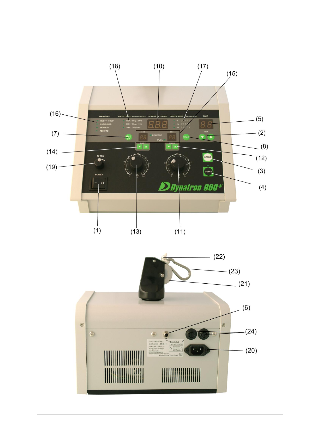
11. HOLD FORCE CONTROL KNOB
Hold Force is set by using the circular knob located on the right-hand side of the device. There are
three numbered circles surrounding the knob. The inside circle indicates force in Newtons, the middle
circle indicates kilograms, while the outside circle indicates force in pounds. Force is selected by
aligning the gray dot on top of the knob with the desired Newtons/ kilograms/pounds of force desired.
Hold Force ranges from 4 –200 lb; 2 –91 kg; or 20 –890N. The selected force will be displayed in
the Traction Force Display Window as the knob is turned.
12. HOLD FORCE TIMER
Located immediately above the “Hold Force”knob, Hold Time is selected by pressing the arrow
selector keys under the Hold display window. This display indicates the amount of time the rope
tension will Hold after reaching the Hold Force set for the current treatment. Hold Force Time ranges
from 1-99 seconds and may be adjusted in 1 second intervals. When a static traction treatment is
desired, press the down the arrow key until “- -” appears in the Hold Display Window.
13. REST CONTROL KNOB
Rest Force is set by using the circular knob located on the left-hand side of the device. There are three
numbered circles surrounding the knob. The inside circle indicates force in Newtons, the middle circle
indicates kilograms, while the outside line indicates force in pounds. Force is selected by aligning the
gray dot on top of the knob with the desired Newton/ kilograms/pounds of force desired. Hold Force
ranges from 0 –197 lb.; 0 –90 kg; 0 –890N. The selection will be displayed in the Traction Force
Display Window as the knob is turned.
14. REST FORCE TIMER
Located immediately above the “Rest Force” knob, Rest Time is selected by pressing the arrow
selector keys under the Rest Display Window. This display indicates the amount of time the rope
tension will Rest following the release phase of the traction cycle. Rest force time ranges from 1-99
seconds and may be adjusted in 1 second intervals. When a static traction treatment is desired, press
the down the Rest Force Arrow Key until “- -” appears in the Rest Display Window.
15. PERFORMANCE INDICATION LAMPS (STATUS INDICATORS)
The Performance Indication Lamps are located directly in the center of the control. During a traction
treatment, the Performance Indication Lamps or status indicators supply the following
PULL: Rope tension is increasing from "Rest" to "Hold."
HOLD: Tension is holding at set Hold Force. Indicator flashes as Hold Force Timer counts
down.
RELEASE: Tension decreasing from "Hold" to "Rest."
REST: Tension is holding at set Rest Force. Indicator flashes as Rest Force Timer counts
down.
16. WARNING INDICATION LEDS
The Warning Indication LEDs are located at the top left-hand corner of the device faceplate and are
listed under the heading “WARNING.”During a traction treatment, the green Warning LEDs will
become illuminated according to adverse operational conditions affecting the device. Following is a
list of the Warning Indicators and their functional warnings:
SERVICE: System is malfunctioning - call for Service (800) 874-6251
MIN.>MAX: "Rest" dial setting is greater than "Hold" dial setting
OVERLOAD: Hold force is 8 kg or more greater than the force selected
REMOTE: Illuminated when patient presses the Remote Stop Key
17. POUND/KILOGRAM/NEWTON KEY
Using the LB/KG/N key located under Force Unit on the front of the faceplate, the user may choose
pounds, kilograms, or Newtons to be displayed on the Traction Force Display. As the key is pressed,
the LED next to the active selection will be illuminated.

Dynatron 900+™
7
18. MAX FORCE LEDS
Under the Max Force heading, three maximum force selections are listed. Selection is made by holding
down the “Rest” Key while pressing the SP Key. The LED next to each Max Force selection becomes
illuminated when the selection is active.
890N / 91kg / 200lb
490N / 50kg / 110lb
180N / 18kg / 40lb
19. SPEED CONTROL KNOB
This knob labeled “Speed” controls the variable "Pull" and "Release" speed of the rope. The rope
speed is increased by turning the knob to the right and reduced by turning the knob to the left. Rope
Speed can be adjusted on a gradient scale of slow to fast (8 lbs.-17 lbs. per second).
20. POWER SOCKET
Plug the Dynatron 900+ power cord firmly into the power socket located on the back of the device
prior to plugging the device into a wall socket. Do not place the cord or the device in a place where the
cord could be tripped over or accidentally pulled out of its socket during a treatment.
21. TRACTION PULLEY
The Traction Pulley can be rotated to any desired position.
22. TRACTION CORD
The traction rope is connected to the spring loaded clip by a knot.
23. SPRING LOADED TRACTION CLIP
The traction Clip is used to attach the traction belts to the traction
device. When operating the device, the traction clip should be
situated with the clip opening facing up as illustrated in the
diagram.
24. FUSES
The Dynatron 900+ requires two fuses:
F 1.6A 250V (100V, 110V, 120V)
F 0.8A 250V (220V, 230V, 240V)
SAFETY SYSTEMS
Warning Alarms will sound under the following conditions:
1. Overload (Hold Force setting is greater than maximum value of the selected range).
2. Traction force exceeds preset force by approximately 8 lbs.
3. Remote Switch is pressed
4. Rest Force setting is equal or greater than the Pull Force setting.
5. Device malfunctions
6. Traction force exceeds 200±4lb. (91±2kg /890±20N)

Dynatron 900+™
8
SECTION III
OPERATING INSTRUCTIONS
This section contains detailed procedures for the operation of the Dynatron 900+ Traction Unit. These
procedures are designed to familiarize the user with the operation and function of the device. Read this
section thoroughly along with all contraindications, warnings, and precautions before operating this device.
WARNING
•Thoracic, Pelvic and Cervical harnesses must be securely in place before traction treatment
begins.
•Always STOP a treatment before removing, or adjusting harnesses.
•Check the traction cable for knots, twisting, fraying and damage of any kind.
•Never use worn or damaged harnesses as these may result in injury to the patient or lessen
the effectiveness of a treatment.
•See the contraindications, warnings, and precautions in this manual before administering a
treatment to a patient.
•The patient controlled REMOTE EMERGENCY STOP cable must be inserted into the front of
the Dynatron 900+ device before powering-on the device.
Prior to treatment, prepare all belts and harnesses according to manufactures directions and carefully
position the patient.
CERVICAL,THORACIC AND PELVIC HARNESSES. The cervical, thoracic and pelvic harnesses
must be properly fitted according to manufacturers’instructions. Belts should be securely
tightened without creating discomfort. Harnesses secure the patient to the traction device while
supporting the musculature, thus allowing for the proper application of the distraction forces.
€ POSITIONING THE PATIENT AND TABLE.As the effect and effectiveness of traction are related
to the position of the body as well as the force and duration of pull, make sure that the
positioning of the patient and the table are according to prescribed protocols. The use of
pillows or bolsters under the arms, head, knees, or ankles may be necessary to achieve proper
positioning. See published literature.
QUICK SETUP INSTRUCTIONS
1. Prepare the patient for the traction treatment. Make sure all belts and harnesses are securely attached.
2. Plug in the remote stop cable and hand it to the patient.
3. Turn on the Dynatron 900+ device.
4. Set Treatment Time: (1-99 min.)
5. Set Hold Force Timer: (1-99 sec.)
6. Set Rest Force Timer: (1-99 sec.)
7. Set Hold Force: (4 –200 lbs. or 2 - 91 kg.)
8. Set Rest Force: (0 –197 lbs. or 0 - 90 kg.) Must be set lower than Hold Force value.
9. Adjust Speed: Range: Slow to Fast
10. Press START

Dynatron 900+™
9
DETAILEDTREATMENT SETUP
1. According to manufactures’ instructions, prepare the patient for treatment. Make sure all belts
and harnesses are securely attached.
2. The Remote Stop cable must be plugged into the console before the device is turned “on.”
Connect the Remote Stop plug to the Remote Jack located in the center of the rear panel and
hand the Remote Stop switch to the patient.
3. Turn the Power Switch to “1”(on). The On/Off Toggle switch is located on the lower
left-side of the control panel. When the toggle switch is in the “1” (on) position, the LED above
the Reset Key is illuminated green. The digital display windows are also illuminated green
indicating that there is power to the device.
4. Set Treatment Time: (1-99 min.) Using the up/down arrow keys located immediately under
the Time Display Window, set the treatment time. The treatment time will appear in the Time
Display Window and the display will count down during a treatment. Treatment time ranges
from 1-99 minutes and may be adjusted in 1 minute intervals.
Note: Traction forces may be changed during treatment; however the Start Key must be pressed
after each change. Changes made during the treatment, will not take effect until the next new
Hold/Rest cycle begins.
4. Set Hold Force Time (1-99 sec.). Located directly above the “Hold Force” knob, Hold Time
is selected by pressing the up/down arrow keys below the Hold Display. This selection
determines the amount of time the traction tension will hold after reaching the set Hold Force.
Hold Force Time ranges from 1 - 99 seconds and may be adjusted in 1 second intervals. When
a Static traction treatment is desired, set the Hold Time at “- -”.
5. Set Rest Force Time (1-99 sec.). Located directly above the “Rest Force” knob, Rest Time is
selected by pressing the up/down arrow keys below the Rest Display. This timer determines the
amount of time the Rest tension will hold after reaching the preset Rest Force. Rest Force Time
ranges from 0 - 99 seconds and may be adjusted in 1 second intervals. When a static traction
treatment is desired, set the Hold Time at “- -”. The Rest Force setting is ignored.
6. Set Hold Force (4 –200 lbs.; 2 –91 kg; or 20 –890N). Hold Force is set by using the
circular knob located on the right-hand side of the control panel. Three numbered circles
surround the knob, the inside circle indicates force in Netwons, the middle circle in kilograms,
while the outside circle indicates force in pounds. Force is selected by aligning the gray dot on
top of the knob with the desired/ pounds/kilograms of force indicated on the circles. Hold force
ranges from 4 –200 lbs.; 2 –91 kg; or 20 –890N.
7. Set Rest Force (0 –197 lb.; 0 –90 kg; 0 –890N). Rest force is set by using the circular knob
located on the left-hand side of the control panel. Three numbered circles surround the knob,
the inside circle indicates force in Netwons, the middle circle in kilograms, while the outside
circle indicates force in pounds. Rest Force is selected by aligning the gray dot on top of the
knob with the desired/ pounds/kilograms of force indicated on the circles. Rest force ranges
from 0 –197 lb.; 0 –90 kg; 0 –890N.
9. Adjust Speed (8 lbs.-17 lbs. per second). Adjust the variable "Pull" and "Release" speed of the
rope by using the Speed knob located on the left side of the control panel. The rope speed is
increased by turning the knob to the right and reduced by turning the knob to the left. Rope
Speed can be adjusted between slow and fast (8 lbs. -17 lbs. per second).
10. Press Start. Press Start and the treatment begins. If a beeper sounds when Start is pressed at
the beginning of a treatment, be sure that the “Rest” Force is set lower than the “Hold” Force.
Press the Reset Key to reset the alarm and indicator lamps.

Dynatron 900+™
10
11. At the end of a treatment, the 900+ unit will beep (unless muted). The LED above the Rest key
will flash, the Treatment Time Display Window will flash “00” and the tension on the rope will
ramp down to 4 lbs. Press the Reset Key to conclude the treatment and release all tension from
the rope. The 900+ is now ready for program changes or to setup a new treatment.

Dynatron 900+™
11
Intermittent Cycle
Longer RampTime
Harmonic Cycle
Static Cycle
ADDITIONALTRACTION MODES –QUICK SETUP INSTRUCTIONS
STATIC INSTRUCTIONS
1. Prepare the patient for the traction treatment. Make sure all belts and harnesses are securely
attached.
2. Plug in the remote stop cable and hand it to the patient.
3. Turn on the Dynatron 900+ device.
4. Set Treatment Time: 1-99 min.
5. Set Hold Force Timer: “- -”sec.
6. Set Hold Force: 2 - 91 kg. or 4 –200 lbs.
7. Adjust Speed Fast
8. Press Start
INTERMITTENT INSTRUCTIONS
1. Prepare the patient for the traction treatment. Make sure all belts and harnesses are securely
attached.
2. Plug in the remote stop cable and hand it to the patient.
3. Turn on the Dynatron 900+ device.
4. Set Treatment Time: 1-99 min.
5. Set Hold Force Timer: 1-99 sec.
6. Set Rest Force Timer: 1-99 sec.
7. Set Hold Force: 4 –200 lbs. or 2 - 91 kg.
8. Set Rest Force: 0 –197 lbs. or 0 - 90 kg. Must be set
lower than Hold Force value.
9. Adjust Speed Fast: Intermittent Cycle
Slower: Intermittent Cycle with
Longer Ramp Time
10. Press START
HARMONIC INSTRUCTIONS
1. Prepare the patient for the traction treatment.
Make sure all belts and harnesses are securely attached.
2. Plug in the remote stop cable and hand it to the patient.
3. Turn on the Dynatron 900+ device.
4. Set Treatment Time: (1-99 min.)
5. Set Hold Force Timer: (01 sec.)
6. Set Rest Force Timer: (00 sec.)
7. Set Hold Force: (4 –200 lbs. or 2 - 91 kg.)
8. Set Rest Force: (0 –197 lbs. or 0 - 90 kg.) Must be set
lower than Hold Force value.
9. Adjust Speed Slow (minimum setting)
10. Press START

Dynatron 900+™
12
Intermittent Cycle
Longer RampTime
STEPLESS PROGRESSIVE
1. Prepare the patient for the traction treatment. Make sure all belts and harnesses are securely
attached.
2. Plug in the remote stop cable and hand it to the patient.
3. Turn on the Dynatron 900+ device.
4. Set Treatment Time: 1-99 min.
5. Set Hold Force Timer: 1-99 sec.
11. Set Rest Force Timer: 1-99 sec.
12. Set Hold Force: 4 –200 lbs. or 2 - 91 kg.
13. Set Rest Force: 0 –197 lbs. or 0 - 90 kg. Must be set
lower than Hold Force value.
14. Adjust Speed Slow (minimum setting)
15. Press START
NOTE: AS A SAFETY PRECAUTION,IT IS NECESSARY TO RESET BOTH THE HOLD AND
REST FORCES WHENEVER THE POWER SWITCH IS ARE TURNED ON.FAILURE TO DO
SO WILL RENDER THE DEVICE INOPERABLE.
SPECIAL USAGE PROCEDURES
ADJUST HOLD/REST FORCES AFTER ATREATMENT IS IN PROGRESS
1. Once the initial Hold Force is reached during a treatment, set the Hold or Rest Force parameters
to the new values.
2. Press the Start Key. The change will not take place until the next full Hold/Rest cycle.
3. In static mode, the Dynatron 900+ device will not accept any change until the Reset Key is
pressed.

Dynatron 900+™
13
SECTION IV
CONTRAINDICATIONS,WARNINGS,AND PRECAUTIONS RELATEDTO
MECHANICAL SPINAL DECOMPRESSION
Traction Therapy must be prescribed by a licensed practitioner following an appropriate physical
examination and diagnostic analysis.
The Dynatron 900+ Traction system is intended for medical purposes for use in conjunction with traction
accessories such as belts and harnesses to exert therapeutic pulling forces on the patient’s body primarily for
the cervical and lumbar areas.
CAUTION: Cervical Traction should never be attempted in traumatic conditions that have not
been evaluated to rule out a fracture of dislocation.
CONTRAINDICATIONS
Pregnancy
Primary or Metastatic Neoplasm in the spine
Vertebral or Spinal Fractures or Instability
Osteoporosis
Prior Lumbar Fusion with Fixation Hardware
Cauda Equina Syndrome
Spondylolisthesis
Spondylolysis
Congenital Abnormalities of the Spine
Patient under 15 years of age
Spinal Cord Compression
Rheumatoid Arthritis
Spinal Meningitis or Arachnoiditis
Advanced disc degeneration or advanced herniation
Inflammatory, infectious, or neoplastic conditions
Acute joint and/or soft tissue injury
Any condition that grows worse after treatment
The presence of vascular compromise
PRECAUTIONS &WARNINGS
Ligamentous Strains and Joint Hypermobility.
Patient’s with “Traction Anxiety” causing muscles to become over tense and/or
cardiac/respiratory insufficiencies.
Discontinue treatment immediately if there is an increase in symptoms or pain or if paresthesia
(prickling or tingling that has no objective cause) is experienced.
Avoid improper extension during cervical traction. Rupture of the cervical esophagus may occur.
Excessive duration and/or traction weight can cause thrombosis of the internal jugular vein.
Abdominal Pressure. Properly administered mechanical traction requires the use of belts and
harnesses/corsets. While such devices can be comfortably applied, they do produce pressure.
Patients who have conditions such as hiatal hernias, uncontrolled hypertension, aortic aneurysm,
or even severe hemorrhoids may not tolerate traction treatments.
Joint Hypermobility. This concept relates to RA and Pregnancy which have already been listed
under Contraindications, however, it is repeated here to make the point that when the
examination of the patient identifies hypermobile spinal segments, these segments must either be
protected from the traction force or traction should not be applied.

Dynatron 900+™
14
SECTIONV
TECHNICAL INFORMATION
SUGGESTED MAINTENANCE SCHEDULE
SERVICETO BE PERFORMED BY ATECHNICIAN
ANNUAL CALIBRATION
It is recommended that the Dynatron 900+ device be sent to the manufacturer for annual calibration.
MAINTENANCE PERFORMED BY USER
1. Inspect the Dynatron 900+ ropes/cables and connectors daily for wear and damage. Replace
accessories as needed.
2. If the device is dropped, or if damage is sustained due to lightning, severe power surge,
submersion in water, or other incident that could cause damage to electronic components, the
device must be examined by a Dynatronics’technician before being returned to clinical use.
3. Inspect device air vents periodically to ensure air flow is not blocked. An ordinary household
vacuum hose may be used to clean dust from the external air vents.
1. Immediately report any device malfunction to Dynatronics’ Customer Service Department
(800) 874-6251.
CAUTION
Excluding rope and fuse replacement, refer servicing to qualified service personnel.
Clean only with a damp cloth. Cleaning the device with water or spraying liquid cleaning agents
on the device may cause damage to the unit and may endanger the life of the patient.
The unit may only be opened and serviced by authorized personnel.
Unplug the unit before opening.
Dynatronics recommends that the Dynatron 900+ be calibrated annually to ensure the unit is
working at peak performance.
When disposing of a Dynatron 900+ unit, comply with the laws and procedures required in your
area according to directives in ISO-14000.
Do not substitute unauthorized parts.
WARNING
Never clean the device while it is attached to a patient.
Keep all food and liquids away from the device and its accessories
If the device malfunctions, immediately press the Reset Key to release rope tension. When the
tension if completely released, turn off the device.
NOTE: BEFORE sending a device to Dynatronics for service, you must FIRST obtain a return
authorization number. Call your Dynatronics ’Representative or Dealer for assistance. If unable to
reach your Dynatronics’ Representative or Dealer, call Dynatronics’ Customer Service Department
at (800) 874-6251 and discuss any problems or required service to save time and ensure the machine
is returned to you as quickly as possible. See Section on the following page “Returning a Unit for
Repair.
WARNING: For continued protection against risk of fire, replace fuses only with type:
F 1.6A 250V (100V, 110V, 120V) ; F 0.8A 250V (220V, 230V, 240V)

Dynatron 900+™
15
RETURNING A UNIT FOR REPAIR
If it becomes necessary to return the Dynatron 900+ for repair, contact your Dynatronics’ Dealer for
assistance. If unable to contact your Dynatronics’ Dealer, call Dynatronics’ Customer Service (800)
874-6251. The following information must be supplied when calling Dynatronics’ Customer Service to
obtain a return Service Order Number (SVO):
1. User name and address
2. User phone number
3. Serial number of the device
4. A description of the problem with the device
After receiving the Service Order Number (SVO), the number should be clearly written on the outside of the
shipping container.
PACKAGING AND SHIPPING
All defective or broken parts should be shipped back to Dynatronics in the original shipping container. These
containers are designed to withstand the punishment of shipping. If the original containers are not usable, find
containers that are similar in protection so damage in shipping will be prevented. The person or company
sending the unit to Dynatronics is responsible for any shipping damage resulting from a poorly packaged part or
device.
CARE AND CLEANING INSTRUCTIONS
•Clean the outer surface of the Dynatron 900+ device with a slightly damp or lightly moistened cloth.
Mild household cleaners work well on the frame. Do not spray the solution directly on the unit. First
moisten the cloth and then wipe the unit off. Solvents, caustic solutions, or harsh or abrasive cleaners
must never be used.
•Avoid stretching electrical cords to full length, bending sharply or wrapping tightly. Undue stress on can
damage connections.
•Keep all food and liquids away from the device and its accessories; spills can cause costly damage to the
device and repairs for this type of damage are not covered by the warranty.
ENVIRONMENTAL CONDITIONS
Transport and Storage
This equipment, while packed for transport or storage, should not be exposed to environmental
conditions outside the following ranges:
a) an ambient temperature range of -40°C
b) a relative humidity range of 10% to 100% including condensation
c) an atmospheric pressure range of 500 hPa to 1060 hPa
Operation
This equipment is designed to operate in normal use under the following environmental conditions:
a) an ambient temperature range of +10°C
b) a relative humidity range of 30% to 75% including condensation
c) an atmospheric pressure range of 700 hPa to 1060 hPa
+70°C
+40°C

Dynatron 900+™
16
SECTIONVI
ASSEMBLY AND MAINTENANCE
PULLEY HEAD
Whenever the Pulley Head is replaced or removed from the device, turn the pulley head to the left
until the breach points are aligned and the pulley easily slips from the enclosure. Do not force.
REMOVINGTHE CHASSIS
1. Remove the two screws from the back panel of the chassis (A).
2. Remove the bottom plate and side panels will fall free.
Table of contents
Other Dynatron Laboratory Equipment manuals
Popular Laboratory Equipment manuals by other brands

Apera Instruments
Apera Instruments 2401-C user manual

PI
PI A-110.050 user manual

Esco Medical
Esco Medical Miri MRI-6A10/XQ-1 Installation procedures

Bego
Bego Miditherm 100 MP Translation of the original instructions

Endress+Hauser
Endress+Hauser Analytik Jena Biometra TRobot II 96 G operating manual

Olympus
Olympus R1 instructions

Thermo Scientific
Thermo Scientific TSE Series Operating and maintenance manual

Blue-Ray Biotech
Blue-Ray Biotech TurboQ TCRT-9614 Operation manual

HTL
HTL HTL-SIM operating instructions

Genrui
Genrui WP21B manual

Molecular Devices
Molecular Devices QPix 420 Pre-installation guide

PI
PI A-121 Series user manual