PSI AlgaeTron Guide
AlgaeTron AG 130
Manual and User Guide
Please read this manual before operating this product
PSI, spol. s r. o., Drásov 470, 664 24 Drásov, Czech Republic
FAX: +420 511 440 901, TEL: +420 511 440 011, www.psi.cz

© PSI (Photon Systems Instruments), spol. s r. o.
2
© PSI (Photon Systems Instruments), spol. s r. o. (hereinafter PSI), 2019
This document and its parts can be copied or provided to a third party only with the express permission of PSI.
The contents of this manual have been verified to correspond to the specifications of the device. However, deviations cannot
be ruled out. Therefore, a complete correspondence between the manual and the real device cannot be guaranteed. The
information in this manual is regularly checked, and corrections may be made in subsequent versions.
The visualizations shown in this manual are only illustrative.
This manual is an integral part of the purchase and delivery of equipment and its accessories and both Parties must abide
by it.

© PSI (Photon Systems Instruments), spol. s r. o.
3
TABLE OF CONTENTS
1Warnings and Safety Precautions ................................................................................................................................... 4
2Technical Specification.................................................................................................................................................... 6
3General Information ....................................................................................................................................................... 7
4Components of AG 130................................................................................................................................................... 8
5Device Description and Instalation ................................................................................................................................. 9
5.1 Device Installation ................................................................................................................................................. 9
5.2 Description of the AlgaeTron Control Unit Front Panel ...................................................................................... 10
5.3 Description of the AlgaeTron Rear Panel and Connection to 230 or 110 V Power Supply ................................. 11
5.4 Description of the AlgaeTron Interior Space ....................................................................................................... 12
5.5 Description of the AlgaeTron Shelving ................................................................................................................ 13
6Optional Modules ......................................................................................................................................................... 14
6.1 Orbital Shaker...................................................................................................................................................... 14
6.1.1 Shaker Installation........................................................................................................................................... 14
6.1.2 Shaker Control................................................................................................................................................. 15
6.1.3 Technical Data................................................................................................................................................. 16
7AlgaeTron AG 130 Control ............................................................................................................................................ 17
8Control Menu Tree........................................................................................................................................................ 18
Examples of Light Protocols Configured Via the Control Unit Front Panel ....................................................................... 26
Circadian Cycle.............................................................................................................................................................. 26
Pulse Cycle .................................................................................................................................................................... 27
Sine Circadian Cycle ...................................................................................................................................................... 29
9Warranty Terms and Conditions ................................................................................................................................... 31
10 Troubleshooting and Customer Support ................................................................................................................. 32
© PSI (Photon Systems Instruments), spol. s r. o.
4
1WARNINGS AND SAFETY PRECAUTIONS
Read this manual carefully before operating the device. If you are not sure about anything in the manual, contact the
manufacturer for clarification.
By accepting the device, the customer agrees to follow the instructions in this guide.
Always follow corresponding manuals while working with the AlgaeTron device or doing the maintenance.
It is forbidden to interfere with the hardware of the AlgaeTron device in any way without previous agreement with the
manufacturer.
The following table presents basic highlight symbols used in this manual:
Symbol
Description
Important information, read carefully.
Complementary and additional information.
Tab. 1 Used symbols.
PLEASE READ THE FOLLOWING INSTRUCTIONS CAREFULLY BEFORE TURNING THE ALGAETRON ON:
•Remove all packaging and transit protectors before connecting the AlgaeTron to the electricity supply.
•Let the AlgaeTron stand up after the transport and WAIT AT LEAST 12 HOURS before plugging it in.
•Use only the cables supplied by the manufacturer.
•Keep the device dry and avoid working in high humidity environment!
•The manufacturer is not responsible for any damage due to improper or incompetent operation!

© PSI (Photon Systems Instruments), spol. s r. o.
5
GENERAL ELECTRICAL SAFETY GUIDELINES:
•Routinely check the devices and their wiring.
•Replace worn or damaged cords immediately.
•Use electrical extension cords wisely and do not overload them.
•Place the devices on a flat and firm surface. Keep them away from wet floors and counters.
•Avoid touching the device, socket outlet or switch if your hands are wet.
•Do not perform any alterations to the electrical part of the devices or their components.
WARNING:
THE ALGAETRON AG 130 IS CONSIDERED CLASS 1M* LED PRODUCT. LED RADIATION MAY BE
HARMFUL TO EYE, AVOID DIRECT AND STRONGLY REFLECTED EXPOSURE. IT IS REASONABLE TO USE
PROTECTIVE GLASSES.
*Class 1M: Laser and LED equipment that is safe under reasonably foreseeable conditions of operation
for use with the naked eye. Looking directly into the source of radiation by employing optics within the
beam such as magnifying glass, telescope or microscope can be potentially hazardous.

© PSI (Photon Systems Instruments), spol. s r. o.
6
2TECHNICAL SPECIFICATION
Temperature range:
+15 °C to +50 °C (with maximum illumination)
+10 °C to +55 °C (without illumination)
+10 °C to +55 °C (with maximum illumination) - optional
LED Light Illumination:
LED panel 250 x 350 mm
External Dimensions (H x L x D):
1000 x 550 x 620 mm
Internal Dimensions (H x L x D):
690 x 420 x 400 mm
Growth Area:
0.14 m2
Weight:
55 kg
Internal Volume:
124 l
Air Ventilation:
250 l/h
Refrigerant:
R134a
Power / Power Input:
300 W / 500 W
Compressor:
220 –240 V; ~ 50 Hz; 160 W; 0.70 A (110 V; 60 Hz)

© PSI (Photon Systems Instruments), spol. s r. o.
7
3GENERAL INFORMATION
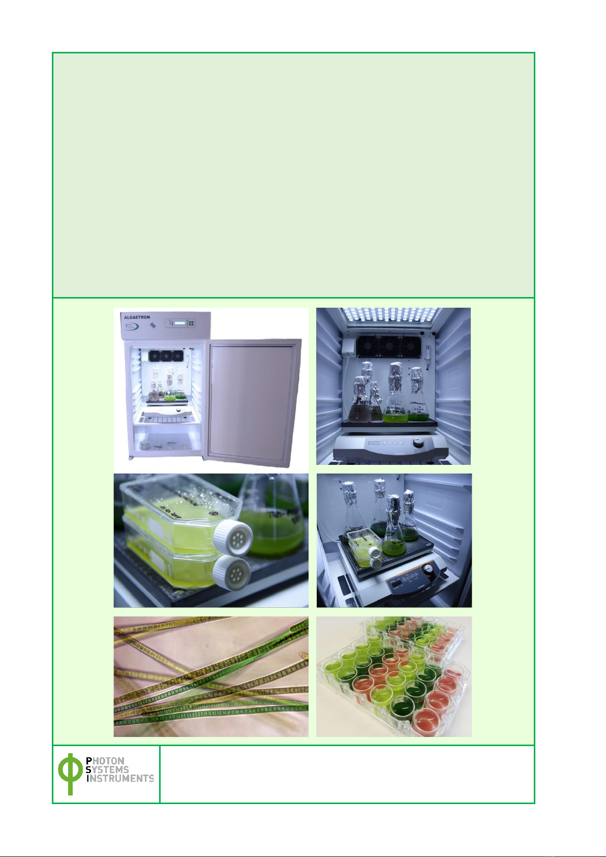
AlgaeTron AG 130 is a floor standing incubated shaker that provides well-defined culture conditions for growing algae and
cyanobacteria in Petri dishes or Erlenmeyer flasks. It is equipped with a large, easy-to-read display screen clearly showing
operating parameters and actual values. Intuitive programming allows multiple parameter changes to timing, light
intensity, light characteristics, temperature, and shaking power.
With its compact dimensions and small footprint, the AlgaeTron AG 130 saves precious laboratory space and is perfect for
small-scale applications. It has one illuminated space with an additional bottom shelve.
AlgaeTron AG 130 features an internal electrical outlet (EU type) for attachment of a dedicated orbital shaker SHK-2013.
Use of different types of shakers is not recommended!
Optionally, the AlgaeTron may be supplemented with a Gas Mixing System GMS 150 that can bring pure or mixed gases
into the incubator to allow cultivation conditions under controlled air compositions. Concentration of gases inside of the
cultivator may be modulated according to user’s defined protocol with optional high-precision Gas Mixing System GMS
150.
This manual contains technical information about AlgaeTron AG 130, description of instrumentation delivered with the
device and step by step instructions for successful installation and operation of the incubator.
Two standard versions are available:
•WIR (Cool or Warm White + Far-Red LEDs) –maximum intensity is 1,000 µmol.m-2.s-1
•RGBIR (Red + Green + Blue + Far-Red LEDs) –maximum intensity is 1,000 µmol.m-2.s-1
Both versions provide:
•Precise control of illumination in mode, intensity and timing;
•Separate control of particular light colors;
•Control of the interior temperature and relative humidity.
Other colors LEDs available.

© PSI (Photon Systems Instruments), spol. s r. o.
8
4COMPONENTS OF AG 130
Please, find below a list of standard AlgaeTron AG 130 components delivered to the customer.
Check the contents of the package and compare it with enclosed standard package list.
List of standard AG 130 components:
•The cultivation unit.
•Two slide out cultivation shelves.
•One inbuilt LED light panel.
•Power cord.
•USB flash disc with Device Control Center.
•Serial cable with USB adapter for data transfer or firmware upgrade.
•Instruction Manual.
•Protective glasses.
Optional accessories/components:
•Gas mixing GMS 150 system.
•Orbital shaker equipped either with non-skid rubber mat or sticky pads or Erlenmeyer attachment of different
size.
•Incorporated module for measuring Ft and QY.

© PSI (Photon Systems Instruments), spol. s r. o.
9
5DEVICE DESCRIPTION AND INSTALATION
5.1 DEVICE INSTALLATION
•Place the AlgaeTron on a flat, firm and dry surface! Let it stand up and wait at least 12 hours before plugging it
in!
•Place the AlgaeTron into a well-ventilated room with ambient temperature not exceeding 25 ºC!
•Do not cover the upper part of the AlgaeTron! Ventilation holes cooling the device electronics are installed on
the AlgaeTron top.
•If you place the rear of the AlgaeTron against the wall, use plastic distance tubes (only for 230V version).
Fig. 1-1 to ensure sufficient distance for heat removal from the condenser!
Fig. 1 Plastic distance tubes.
© PSI (Photon Systems Instruments), spol. s r. o.
10
5.2 DESCRIPTION OF THE ALGAETRON CONTROL UNIT FRONT PANEL
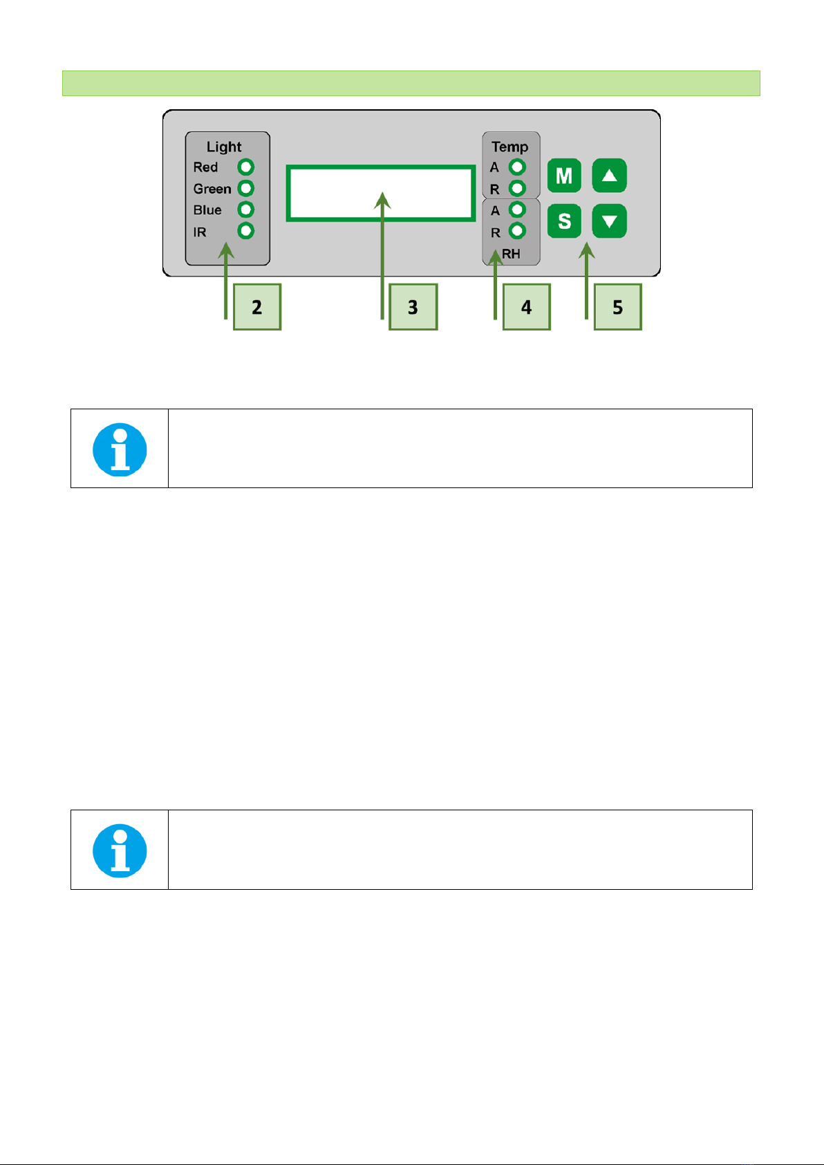
Fig. 2 Front Panel.
[2] Light panel indicators: Indicating whether the corresponding light is active.
Only two LED indicators are mounted for the AG 130 White + IR light version.
[3] Two-line LCD display.
[4] Temperature and Relative humidity (RH) indicators: Indicating the status of thermoregulation and humidity.
[A]: Indicates the Active state of Thermoregulation [Temp] / Humidity [RH]
[R]: Indicates Reaching the desired Temperature [Temp] / Humidity [RH]
[5] Four control keys:
[M]: Used to move back in the menu tree or to exit the menu.
[S]: Used to move forward in the menu tree or to save the selection.
[▲]: Used to move up in the menu or to add value.
[▼]: Used to move down in the menu or to subtract value.
See Chapter AlgaeTron AG 130 Control on page 17 for more information about the AlgaeTron Control
Panel operation.

© PSI (Photon Systems Instruments), spol. s r. o.
11
5.3 DESCRIPTION OF THE ALGAETRON REAR PANEL AND CONNECTION TO 230 OR 110 V
POWER SUPPLY
Fig. 3 Rear Panel.
[6] ON/OFF power switch (mains).
[7] ON/OFF power switch for an optional air pump.
The air pump switch is not included in the standard device version.
[8] Firmware communication connector.
[9] Gas port: Provide connection to an external gas control system (via corrosion resistant connectors and 6 mm
thermoplastic tubing).
External gas control system is not included in the standard device version.
[10] 230 or 110 V power connector: The type of a power connector depends on the supply system in concerned country.
The connector includes a safety fuse (its value in amperes is indicated on the label). The mains cable is supplied by the
manufacturer as a standard device accessory.
[11] Internal outlet fuse related to the inner power sockets.
© PSI (Photon Systems Instruments), spol. s r. o.
12
5.4 DESCRIPTION OF THE ALGAETRON INTERIOR SPACE
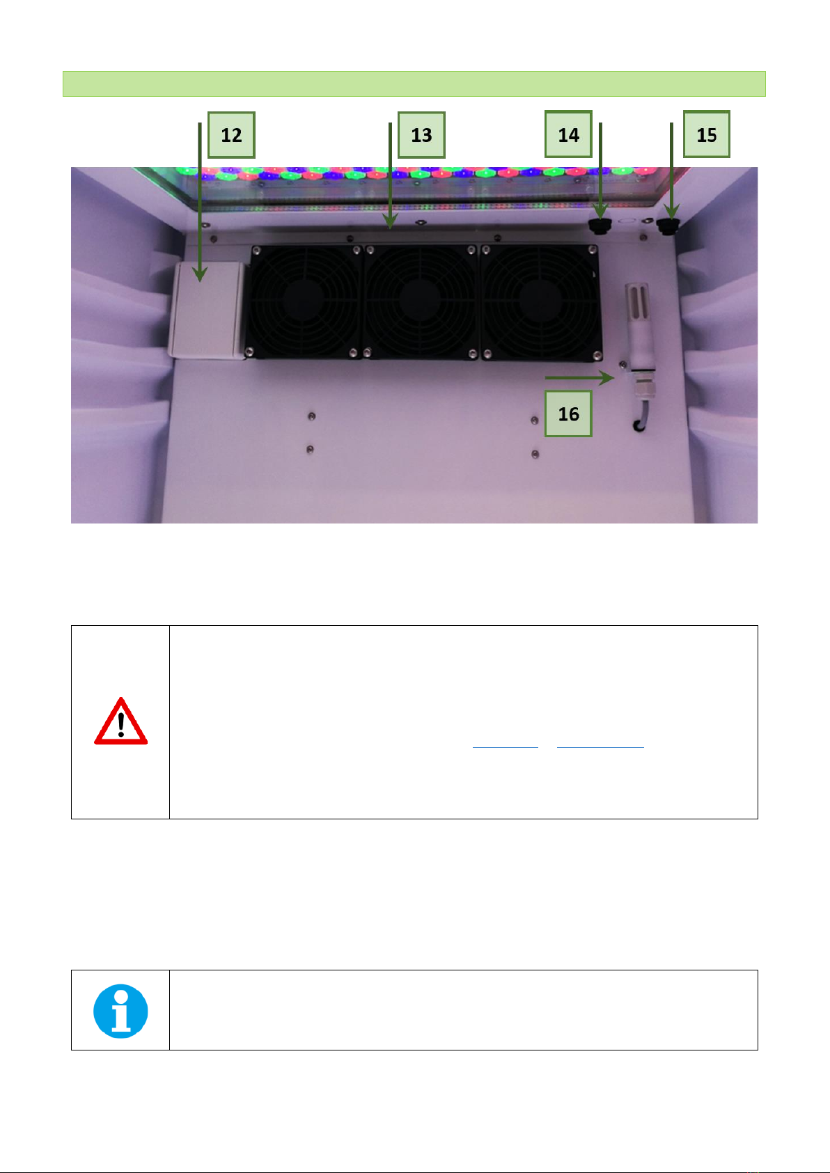
Fig. 4 The back-wall of the AG interior.
[12] Inside electrical socket is intended for connection of supplementary accessories (shaker SHK-2013, etc.) inside the
AlgaeTron. The outlet has a fuse, which is situated on the rear panel of the device (see feature [11] in Fig. 3).
The internal socket in the AG 130 is intended only for use with the Shaker supplied by PSI. Using this
socket for any other appliance is not recommended because it may cause damage to the AG 130 and
it may cause loss of warranty.
If - in an exceptional case - a different appliance should be used by the customer, it always must be
Be aware that using accessories that produce too much heat can influence temperature regulation
inside the AlgaeTron AG 130!
[13] Airflow Fans provide proper air circulation and uniform temperature distribution inside the AlgaeTron AG 130.
[14] Air Inlet is an entry point of air into the chamber (via internal air pump). The air flow rate can represent up to 250 l/min
if the pump is switched ON. When the AlgaeTron is turned ON/OFF, the air pump automatically turns ON/OFF as well.
Optionally, a power switch (ON/OFF) can be mounted for separate control of the air pump [7].
[15] Gas port provide connection to an external gas control system.
The external gas control system is not included in the standard device version.
[16] Temperature and relative humidity detector.

© PSI (Photon Systems Instruments), spol. s r. o.
13
5.5 DESCRIPTION OF THE ALGAETRON SHELVING
For the illustration of inner space of the AlgaeTron see Fig. 5. Two shelves [17] and [18] are supplied for placement of
samples or shaker.
The shelf labelled “LOWER” (with wide rear edge) can be positioned in the lowest level only [17]. The shelf labelled “UPPER”
can be positioned in any other level [18].
Fig. 5 The AlgaeTron FS 130 shelving.

© PSI (Photon Systems Instruments), spol. s r. o.
14
6OPTIONAL MODULES
6.1 ORBITAL SHAKER
The supplied orbital shaker is SHK-2013. It has a strong housing made from composite material, which is corrosion resistant
and ensures easy cleaning. The shaking table is equipped with a solid non-skid rubber mat. This makes the whole unit easy
to clean and resistant to abrasion and a wide range of chemicals. Optionally, sticky pads or Erlenmeyer attachments of
different size can be delivered.
The shaker can be operated in two modes: continuous and time-controlled shaking. A digital process timer allows for
unattended operation and can be set from 1 to 999 minutes. When the set time has elapsed, an acoustic alarm will sound
and the operation stops. The rotation speed ranges between 30 –500 rpm and the platform size amounts to 290 –258
mm.
Use of different shakers than SHK-2013 is not recommended! It may cause unpredictable problems
and could result in AlgaeTron damage and loss of warranty.
6.1.1 SHAKER INSTALLATION
Place the shaker into the AlgaeTron AG 130 and plug it into the inner electrical socket [12].
Do not overweight the shaker! Maximum is 5 kg.
Loading capacity:
50 ml flasks: 25 pc
100 ml flasks: 12 pc
250 ml flasks: 9 pc
500 ml flasks: 6 pc
Fig. 6 Orbital shaker.

© PSI (Photon Systems Instruments), spol. s r. o.
15
6.1.2 SHAKER CONTROL
The orbital shaker is controlled through several buttons placed on the front panel.
Fig. 7 Shaker control.
The control panel includes following controls:
A 2-pole master switch (toggle-type, lighted green on the left side of the unit)
B Setting knob, shaking frequency
C Set Time key : time up
D Set Time key : time down
E Select key: display selector: shaking frequency (Act Speed) / time (Act Time)
F LED Time: time appears in display
G LED Speed: rotational speed (shaking frequency) appears in display
H Start / Stop key: to START / STOP shaking action
I LED Start / Stop: lighting, while item is running
J 4-digit display
Continuous shaking:
•Turn item ON with master switch (A).
•Set time with and keys to 000 (depress and together).
•Start continuous operation by hitting the Start / Stop key. Start and Speed LEDs turn on, shaking frequency is displayed
(4-digit display).
•Set shaking frequency with knob (B).
•Hitting Start / Stop key will stop shaking.
Timer controlled shaking:
•Set time between 0 and 999 minutes with Set Time or Set Time keys.
•Short hits on the keys change time setting slowly, whereas depressing keys is going to change time rapidly. Depressing
the Set Time and Set Time keys reset the timer to 000.
•Depressing the Start / Stop key (H) starts shaking at the frequency selected with knob (B) and for the time interval set
before. Start LED turns ON.
•Time lapse appears in a 3-digit display. Time LED turn ON.
•Current shaking action may be discontinued with the Start / Stop key (H). Actual time won’t change. Hitting this Start /
Stop key continues shaking at the moment it had been discontinued.
•In case of a power supply failure or interruption (item turned OFF), this feature is lost.
•Hitting the Select key during timer-controlled operation, you may change display from time to shaking frequency and
vice versa.
•Speed LED turns ON. Timer LED flashes to indicate timer operation mode.

© PSI (Photon Systems Instruments), spol. s r. o.
16
•Timer LED also flashes, when timer-controlled operation was discontinued with the Start / Stop key.
Repetition:
•Repeating last timer controlled operation does not require new time setting, as long as you did not touch the master
switch.
Time modification during shaking operation:
•Time setting may be changed during shaking, while timer is running and even when timer controlled operation was
discontinued.
•Memory timer will keep initial value in its memory.
6.1.3 TECHNICAL DATA
Shaker speed:
30 –500 RPM
Orbit:
10 mm
Permissible Ambient Temperature:
0 –50 °C
Permissible Ambient Humidity:
80 %
Weight:
8 kg
Maximum Loading Capacity:
5 kg
Dimensions (D x W x H):
375 x 320 x 125 mm
Power Supply:
115 / 230 VAC +/-10%; ~ 50/60 H

© PSI (Photon Systems Instruments), spol. s r. o.
17
7ALGAETRON AG 130 CONTROL
Explanation of symbols and color differentiation used in the graphical presentation:
The following pages show a graphical representation of the operation scheme for the AlgaeTron. This scheme is structured
in five levels. Individual levels are marked with a different color for an easier orientation in the scheme.
The AlgaeTron AG 130 front panel does not reflect this color differentiation.
•Main menu - Blue
•First-level nested sub-menu - Yellow
•Second-level nested sub-menu - Green
•Third -level nested sub-menu - Orange
•Fourth-level nested sub-menu –Grey
See pages 18 - 27 of this Manual for the graphical representation of individual menus and for explanations of their
functions.
[M] key Used to move back in the menu tree or to exit the menu.
[S] key Used to move forward in the menu tree or to save your selection.
[↑] key Used to move up in the menu or to add value.
[↓] key Used to move down in the menu or to subtract value.
Full-line arrows are used for the [S] key.
Dashed-line arrows are used for the [M] key.
Dotted-line arrows are used for the [UP/DOWN] keys.
After 10 seconds of no activity within the menu settings the display on the AlgaeTron returns to the current temperature
readings.

© PSI (Photon Systems Instruments), spol. s r. o.
18
8CONTROL MENU TREE

© PSI (Photon Systems Instruments), spol. s r. o.
19

© PSI (Photon Systems Instruments), spol. s r. o.
20
This manual suits for next models
1
Table of contents
Other PSI Laboratory Equipment manuals


Popular Laboratory Equipment manuals by other brands


Miele professional
Miele professional PG 8583 operating instructions

Domino
Domino DDC3 Operator's reference guide

Cole Parmer
Cole Parmer RS-250 Series instruction manual

Genlantis
Genlantis FirstResponder E900FRUR quick start guide

Cognex
Cognex DataMan 8072 Quick reference guide

Endress+Hauser
Endress+Hauser Analytik Jena multi N/C operating manual


