Erco&Gener GenIP 30i User manual
L’esprit Modem
User Guide
GenIP 30i
Reference: EG_GenIP30i_1016_UG_004_UK
Revision: 004
Date: 10/11/2015
http://www.ercogener.com Dct_427_02

http://www.ercogener.com
Document History
Rev. Modifications Author Date Validation Date
000 CREATION YST 10/05/2012 LGO 14/05/2012
001
§ 3.2.1.2 Screw connectors and § 6.7 Input /
Output Interface la pin 19 O4-is actually O3-
§ 5.2.1.1 Definition of course of actions in a
scrip adding this paragraph.
§ 5.2.3.1 Management of characters in the
buffer
§ 5.2.6 Macro Commands update the
presentation, adding macros.
§ 5.2.7 Dynamic messages update the
message list.
§ 5.2.8.2 Sequence of script adding an
application example.
§ 5.2.16.1 Connect disconnect WAN link in the
script adding this paragraph.
§ 5.2.26 Hardware Option adding this
paragraph.
§ 5.2.27 Inactivity Timer adding this paragraph.
§ 5.3.2.3 Format of data and number of
registers that can be read Adding parameter
INVERTED.
§ 5.3.7 Addressable memory of the GenIp
modification updating the address space.
§ 6.8 External Supply VOand § 7.2.7 External
power supply VO uploading the limitation of
the output VO.
§ 7.2.5.2 Analog Inputs in current (0-25mA)
adding information on the conversion range.
§8.1 General security added used precaution
YST 03/05/2013 LGO 03/05/2013
002
Fixed dialing paragraph
§5.2.5 Add macro Command
§5.2.7.1 to 5.2.7.3 Dynamics messages
§ 5.2.8.2 Default value script number
§ 5.2.9.1 Integrate address 132.xxx.xxx.xxx
§5.2.15 Setting GSM CSD
Update screen shot ModBus
§ 5.3.2.1 ModBus Structure
Update comsumption § 7.2 Electrical
characteristics
LGO
YST 26/03/2014 YST 14/10/2014
003
Add
§ 5.4 Information on SNMP function
§ 7.2.8 Output Input and External Power
supply behavior
LGO 22/10/2014 YST 24/10/2014
004
Add
§ 5.2.6 Macro command reset modem
§ 5.2.8 PHP language
§ 5.2.24 IPsec Tunnel
§ 5.2.25.1 Chart used
§ 7.2.5.1Analog Inputs in Voltage (0-25V
§ 7.2.5.2 Analog Inputs in current (0-25mA
§ 7.2.6.2 Add scheme Output active
LGO 21/10/2015 YST 10/11/2014
The main modifications of this document compared to the previous version are easily identifiable on the
screen by the blue color of the text.
Dct_427_02

EG_GenIP30i_1016_UG_004_UK Page 3 / 143
TABLE OF CONTENTS
PRESENTATION...............................................................................................................................................8
WARNING .........................................................................................................................................................9
COPYRIGHT ...................................................................................................................................................10
1REFERENCES........................................................................................................................................11
1.1REFERRED DOCUMENTS.................................................................................................................... 11
1.2ABBREVIATIONS ............................................................................................................................... 11
1.3SYMBOLS......................................................................................................................................... 13
2PACKAGING..........................................................................................................................................14
2.1CONTENT ......................................................................................................................................... 14
2.2PACKING CASE................................................................................................................................. 14
2.3MODEM LABELS ............................................................................................................................... 15
3GENERAL PRESENTATION.................................................................................................................16
3.1DESCRIPTION ................................................................................................................................... 16
3.2EXTERNAL CONNECTIONS ................................................................................................................. 17
3.2.1Connections ............................................................................................................................. 17
3.2.1.1Antenna connector.......................................................................................................... 17
3.2.1.2Screw connectors ........................................................................................................... 17
3.2.1.3Sub D 9-pin connector.................................................................................................... 18
3.2.1.4RJ45 Ethernet LAN connector ....................................................................................... 18
3.2.1.5USB connectors .............................................................................................................. 19
3.2.1.6Reset Button.................................................................................................................... 19
3.2.2Accessories supplied.............................................................................................................. 20
3.2.2.1Straight cable 9pin M/F................................................................................................... 20
3.2.2.2Ethernet RJ45 straight cable.......................................................................................... 21
3.2.2.3GSM hinged antenna (SMA-M)....................................................................................... 21
4TECHNICAL CHARACTERISTICS AND OPTIONS..............................................................................22
4.1TECHNICAL CHARACTERISTICS.......................................................................................................... 22
4.2ACCESSORIES AND OPTIONS ............................................................................................................ 23
4.3BACKUP BATTERY ............................................................................................................................ 23
4.3.1Characteristics of the battery................................................................................................. 23
5USING THE GENIP 30I..........................................................................................................................24
5.1STARTING WITH THE GENIP 30I......................................................................................................... 24
5.1.1Assembling and disassembling the GenIP 30i..................................................................... 24
5.1.2SIM card Access ...................................................................................................................... 25
5.1.2.1Insertion Carte SIM.......................................................................................................... 25
5.1.2.2SIM card Removal ........................................................................................................... 25
Descriptions and non-contractual illustrations in this document are given as an indication only.
ERCOGENER reserves the right to make any modifications. Dct_427_02

EG_GenIP30i_1016_UG_004_UK Page 4 / 143
5.1.3Installation of the GenIP 30i.................................................................................................... 26
5.1.4Using the GenIP 30i with the browser ................................................................................... 27
5.2BASIC PRINCIPLE.............................................................................................................................. 32
5.2.1Actions...................................................................................................................................... 32
5.2.1.1Definition of course of actions in a script .................................................................... 32
5.2.1.2Pilot an action in DTMF .................................................................................................. 33
5.2.2Events ....................................................................................................................................... 34
5.2.2.1Planning events............................................................................................................... 34
5.2.3Pattern....................................................................................................................................... 36
5.2.3.1Management of characters in the buffer....................................................................... 36
5.2.4Acknowledgements................................................................................................................. 37
5.2.4.1Acknowledgement via Macro Command...................................................................... 37
5.2.4.2Acknowledgement via DTMF ......................................................................................... 38
5.2.5Remarks about syntax of acknowledgements, Macro Commands, patterns or frames
received upon action starting.............................................................................................................. 39
5.2.5.1Reaction of the GenIP 30i in case of authorized sources and syntax error.............. 39
5.2.6Macro Commands.................................................................................................................... 40
5.2.7Dynamic messages.................................................................................................................. 54
5.2.7.1Identifications and states messages............................................................................. 54
5.2.7.2Systems messages......................................................................................................... 55
5.2.7.3Users messages.............................................................................................................. 57
5.2.8Script......................................................................................................................................... 59
5.2.8.1Creation of a script in GenIP language......................................................................... 59
5.2.8.2Creation of a script in PHP language............................................................................ 62
5.2.8.2.1Header function dedicaded to GenIP....................................................................... 62
5.2.8.3Sequence of script.......................................................................................................... 63
5.2.9IP Information........................................................................................................................... 65
5.2.9.1LAN IP Address managed by the GenIP 30i................................................................. 65
5.2.9.2GenIP 30i in DHCP server............................................................................................... 65
5.2.9.3GenIP 30i as Client DHCP............................................................................................... 65
5.2.9.4Definition of Masquerade ............................................................................................... 66
5.2.9.5Ports management.......................................................................................................... 66
5.2.9.6Incoming PPP connection.............................................................................................. 66
5.2.9.7Outgoing PPP connection.............................................................................................. 66
5.2.10Time out of connection and disconnection on TCP service........................................... 67
5.2.11PIN code and SIM card management ................................................................................ 67
5.2.12Reloading a configuration from a backup file .................................................................. 67
5.2.13Notes about the definition and the behavior of the actions............................................ 68
5.2.14Loss and recovering of network (LAN) ............................................................................. 68
5.2.15Remarks about GSM/WAN/SMS connections................................................................... 69
5.2.16Remarks of WAN connection disconnection of the GenIP 30i....................................... 69
5.2.16.1Connect disconnect WAN link in the script ................................................................. 70
Descriptions and non-contractual illustrations in this document are given as an indication only.
ERCOGENER reserves the right to make any modifications. Dct_427_02
5.2.17Remarks concerning the clock management................................................................... 70

EG_GenIP30i_1016_UG_004_UK Page 5 / 143
5.2.18Remarks concerning the management of the network gateway or LAN....................... 70
5.2.19Remarks concerning the management of the DNS service ............................................ 71
5.2.20Remarks concerning the tools........................................................................................... 71
5.2.20.1Bytes meter...................................................................................................................... 71
5.2.20.2Modem commands tracks.............................................................................................. 71
5.2.20.3System log tracks............................................................................................................ 72
5.2.21Remarks concerning Allowed sources ............................................................................. 72
5.2.21.1Unwanted connections BlackList.................................................................................. 72
5.2.22Remarks about tunnels....................................................................................................... 72
5.2.22.1SSL Tunnel....................................................................................................................... 73
5.2.23Data Logging........................................................................................................................ 74
5.2.24IPSec Tunnel........................................................................................................................ 74
5.2.25User Management and Password...................................................................................... 75
5.2.25.1Creating a User................................................................................................................ 75
5.2.25.2Change Password........................................................................................................... 76
5.2.25.3Hierarchy.......................................................................................................................... 76
5.2.26Remarks about the function Bridge .................................................................................. 78
5.2.27Hardware Option.................................................................................................................. 78
5.2.28Inactivity Timer .................................................................................................................... 79
5.3INFORMATION ABOUT THE FUNCTION MODBUS................................................................................... 80
5.3.1Configuration ........................................................................................................................... 82
5.3.2Modbus Master......................................................................................................................... 85
5.3.2.1Structure of the messages Modbus Master ................................................................. 85
5.3.2.2Function Code authorized.............................................................................................. 86
5.3.2.3Format of data and number of registers that can be read.......................................... 87
5.3.2.4Example of use of a variable.......................................................................................... 88
5.3.3Structure of messages Modbus RTU..................................................................................... 91
5.3.4Structure of messages Modbus TCP..................................................................................... 92
5.3.5Functions codes of the Modbus standards supported........................................................ 92
5.3.5.1Reading of N bits of output............................................................................................ 92
5.3.5.2Reading of N bits of input .............................................................................................. 93
5.3.5.3Reading of N registers of exploitation.......................................................................... 93
5.3.5.4Reading of N registers of input...................................................................................... 94
5.3.5.5Writing of 1 bit of output ................................................................................................ 94
5.3.5.6Writing of 1 register of exploitation............................................................................... 94
5.3.5.7Writing of N bit of output................................................................................................ 95
5.3.5.8Writing of N registers of exploitation............................................................................ 96
5.3.6Error codes Modbus................................................................................................................ 97
5.3.7Addressable memory of the GenIp ........................................................................................ 98
5.3.8Register of configuration........................................................................................................ 99
5.3.9Reading of digital inputs....................................................................................................... 100
5.3.10Inputs of counting ............................................................................................................. 101
Descriptions and non-contractual illustrations in this document are given as an indication only.
ERCOGENER reserves the right to make any modifications. Dct_427_02
5.3.11Reading/Writing of digital outputs................................................................................... 102

EG_GenIP30i_1016_UG_004_UK Page 6 / 143
5.3.12Reading of analog inputs.................................................................................................. 103
5.3.13Reading/Writing of analog outputs.................................................................................. 104
5.3.14Triggering of actions......................................................................................................... 106
5.3.15Execution of Macro command ......................................................................................... 108
5.4INFORMATION ON SNMP FUNCTION................................................................................................. 110
5.4.1Example of reading a variable and sending SMS............................................................... 110
5.5LEDS OF THE GENIP 30I................................................................................................................. 111
5.5.1PWR led of the GenIP 30i...................................................................................................... 111
5.5.2CONF led of the GenIP 30i .................................................................................................... 111
5.5.3GSM led of the GenIP 30i ...................................................................................................... 111
5.5.4User led of the GenIP 30i....................................................................................................... 112
5.6PROCEDURE FOR UPDATING THE GENIP 30I.................................................................................... 112
5.7TROUBLE SHOOTING....................................................................................................................... 113
6FUNCTIONAL DESCRIPTION.............................................................................................................114
6.1ARCHITECTURE .............................................................................................................................. 114
6.2POWER SUPPLY.............................................................................................................................. 115
6.3ETHERNET LAN LINK...................................................................................................................... 115
6.4RS485 LINK................................................................................................................................... 115
6.5RS232 SERIAL LINK ....................................................................................................................... 116
6.6RESET ......................................................................................................................................... 116
6.7INPUT /OUTPUT INTERFACE............................................................................................................ 116
6.8EXTERNAL SUPPLY VO.................................................................................................................... 117
6.9USB INTERFACE (HOST)................................................................................................................. 117
6.10SOCKET MODULE........................................................................................................................... 117
6.11WATCH DOG .................................................................................................................................. 118
7TECHNICAL CHARACTERISTICS......................................................................................................118
7.1MECHANICAL CHARACTERISTICS..................................................................................................... 118
7.2ELECTRICAL CHARACTERISTICS ...................................................................................................... 119
7.2.1Power supply.......................................................................................................................... 119
7.2.1.1Consumption................................................................................................................. 120
7.2.1.2Consumption in 'Idle' mode ......................................................................................... 121
7.2.1.3Consumption in GSM communication mode ............................................................. 122
7.2.2RS485 link............................................................................................................................... 123
7.2.2.1Position of straps.......................................................................................................... 124
7.2.3Digital Inputs opto-coupled (I3, I4)....................................................................................... 125
7.2.4Digital opto-coupled Output (O3, O4).................................................................................. 127
7.2.5Analog Input (I1, I2)................................................................................................................ 129
7.2.5.1Analog Inputs in Voltage (0-25V)................................................................................. 129
7.2.5.2Analog Inputs in current (0-25mA).............................................................................. 131
7.2.5.3Analog input in logical mode with contact................................................................. 133
7.2.6Analog Outputs (O1, O2)....................................................................................................... 134
Descriptions and non-contractual illustrations in this document are given as an indication only.
ERCOGENER reserves the right to make any modifications. Dct_427_02

EG_GenIP30i_1016_UG_004_UK Page 7 / 143
7.2.6.1Analog Outputs in voltage (0-24V) .............................................................................. 134
7.2.6.2Analog Outputs in Current (0-25mA)........................................................................... 135
7.2.7External power supply VO..................................................................................................... 137
7.2.8Output Input and External Power supply behavior............................................................ 137
7.2.8.1Output behavior............................................................................................................. 137
7.2.8.2Input testing................................................................................................................... 137
7.2.8.3GenIP start up timing.................................................................................................... 137
7.2.9USB Port ................................................................................................................................. 138
7.2.10SIM Interface ...................................................................................................................... 138
7.2.11RF GSM/WAN characteristics........................................................................................... 138
7.2.11.1Frequency band............................................................................................................. 138
7.2.11.2GSM external antenna .................................................................................................. 139
7.3ENVIRONMENTAL CHARACTERISTICS ............................................................................................... 139
7.4STANDARDS/CONFORMITIES ........................................................................................................... 139
8SECURITY RECOMMENDATIONS.....................................................................................................140
8.1GENERAL SECURITY ....................................................................................................................... 140
8.2CARE AND MAINTENANCE................................................................................................................ 141
8.3YOUR RESPONSIBILITY.................................................................................................................... 141
9RECOMMENDED ACCESSORIES......................................................................................................142
10CLIENT SUPPORT...............................................................................................................................142
DECLARATION OF CONFORMITY.............................................................................................................143
Descriptions and non-contractual illustrations in this document are given as an indication only.
ERCOGENER reserves the right to make any modifications. Dct_427_02

EG_GenIP30i_1016_UG_004_UK Page 8 / 143
Presentation
Entirely dedicated to the most critical and sensible industrial applications, the GenIP 30i with its aluminum
Din-rail casing associates the wired connections of high and very high speed (Ethernet / USB) with the
wireless world (GSM / GPRS / and 3G).
Autonomous, simple to configure (intuitive and multi-language interface) and with a high performance (ARM9
processor), it will help you all along your industrial phases concerning alarm and events management,
network interconnection (Ethernet, Modbus), command interpreter and secure storage of critical information.
For added security, the GenIP 30i is equipped with a watchdog hardware and software.
It provides a communication interface GSM / GPRS / 3G and knows how to be available and/or how to
monitor your critical equipments (Notification by email / SMS / WAN /FTP / TCP and Voice in option).
It is also able to interconnect your ASCII protocols to your new Ethernet platforms (Modbus RTU to Modbus
TCP conversion).
5 years warranty, it has the same qualities as all our products: Robustness, Reliability and Long Life.
The GenIP 30i belongs to the DIN-rail range of ERCOGENER.
This document describes the product and provides the following information:
- General presentation,
- Functional description,
- Available basic services,
- Installation and use of the GenIP 30i (first level),
- Trouble shooting,
- Recommended accessories for the use of the product.
For more information concerning this document, ERCOGENER puts at your disposal (on the Internet
www.ercogener.com or upon request) the following elements:
- Application Note
- Release Note
- Client support (Hot-Line)
Descriptions and non-contractual illustrations in this document are given as an indication only.
ERCOGENER reserves the right to make any modifications. Dct_427_02

EG_GenIP30i_1016_UG_004_UK Page 9 / 143
Warning
•ERCOGENER r advises to read carefully all the documents concerning the products GenIp 30i
(User Guide, Application Notes, Command List).
•ERCOGENER cannot be held responsible for:
- The problems due to an inappropriate use of the GenIP 30i.
- The problems due to a wrong configuration
- The problems due to a wrong use of an embedded software application developed and
supplied by a third party.
- The dysfunctions due to the absence or a bad coverage of the GSM, WAN networks.
- The dysfunctions if the product is used for the watching of physical persons where human
life is engaged.
•ERCOGENER reserves the right to modify the functions of its products " GenIP 30i".
- In order to avoid any risk of electrocution, do not open the casing.
- For any functioning, the casing must be closed.
- No internal part can be repaired by the user. The GenIP 30i must be returned to the factory for any repair.
- The GenIP 30i must be placed in a normally ventilated area, out of sources of heat.
- In order to guarantee the electromagnetic compatibility, the length of the USB cable and the supply cable
must not exceed 3 meters.
- The GenIP 30i must not be connected directly to the mains supply; a voltage adapter must be used.
SCRAP THE WORN BATTERIES ACCORDING TO INSTRUCTIONS.
Descriptions and non-contractual illustrations in this document are given as an indication only.
ERCOGENER reserves the right to make any modifications. Dct_427_02

EG_GenIP30i_1016_UG_004_UK Page 10 / 143
Copyright
The reproduction, transfer, distribution or storage of part or the totality of the contents of this document, in
any form, without the prior written authorization of ERCOGENER is strictly prohibited.
GenIP 30i is a trademark of ERCOGENER.
Hayes is a registered trademark of Hayes Microcomputer Product Inc. The names of products and
companies mentioned in this document may be names or trademarks of their respective holders.
The use of some products or services described in this document may require a paying subscription. The
availability of some products or services described in this document may change, depending on the
configurations and the materials.
In some countries, restrictions of use of the devices may be applied. For more information, thank you to
contact your nearest legally qualified local government representative.
ERCOGENER follows a method of continuous development. Consequently, ERCOGENER reserves the right
to change and improve any of its products described in this document, without notice.
The contents of this document are provided “as it is”. Except for the applicable obligatory laws, no guarantee
in any form, explicit or implicit, including but without being limited to it the implicit guarantees of aptitude to
marketing and of appropriateness to a particular use, is granted concerning the precision, the liability or the
contents of this document. ERCOGENER reserves the right to revise or withdraw this document at any time
and without notice.
In any case, ERCOGENER cannot be held responsible for any loss of data or income, as well as particular
damage, incidental, consecutive or indirect.
Descriptions and non-contractual illustrations in this document are given as an indication only.
ERCOGENER reserves the right to make any modifications. Dct_427_02

EG_GenIP30i_1016_UG_004_UK Page 11 / 143
1 References
1.1 Referred documents
Software update Procedure:
EG_GenIP30i_1016_UP_xxx_UK
GSM reference documents:
●GSM 07.05.
●GSM 07.07.
1.2 Abbreviations
Abbreviations Definition
AC Alternative Current
ACM Accumulated Call Meter
AT Attention (prefix for modem commands)
BTS Base Transceiver Station
CLK ClocK
CMOS Complementary Metal Oxide Semiconductor
CS Coding Scheme
CTS Clear To Send
dB Decibel
dBc Decibel relative to the Carrier power
dBi Decibel relative to an Isotropic radiator
dBm Decibel relative to one milliwatt
DC Direct Current
DCD Data Carrier Detect
DCE Data Communication Equipment as Modem...
DCS Digital Cellular System
DSR Data Set Ready
DTE Data Terminal Equipment as Computer...
DTMF Dual Tone Multi-Frequency
DTR Data Terminal Ready
EEPROM Electrically Erasable Programmable Read-Only Memory
EFR Enhanced Full Rate
E-GSM Extended GSM
EMC ElectroMagnetic Compatibility
EMI ElectroMagnetic Interference
ESD ElectroStatic Discharges
ETSI European Telecommunications Standards Institute
FIT Series of connectors (micro-FIT)
FR Full Rate
FTA Full Type Approval
GCF Global Certification Forum
GND GrouND
GPIO General Purpose Input Output
GPRS General Packet Radio Service
GSM Global System for Mobile communications
HR Half Rate
I Input
IEC International Electrotechnical Commission
IMEI International Mobile Equipment Identification
I/O Input / Output
Descriptions and non-contractual illustrations in this document are given as an indication only.
ERCOGENER reserves the right to make any modifications. Dct_427_02

EG_GenIP30i_1016_UG_004_UK Page 12 / 143
LED Light Emitting Diode
MAX MAXimum
ME Mobile Equipment
MIC MICrophone
Micro FIT Family of connectors from Molex
MIN MINimum
MNP Microcom Networking Protocol
MO Mobile Originated
MS Mobile Station
MT Mobile Terminated
NOM NOMinal
O Output
Pa Pascal (for speaker sound pressure measurements)
PBCCH Packet Broadcast Control Channel
PC Personal Computer
PCL Power Control Level
PDP Packet Data Protocol
PDU Protocol Description Unit
PIN Personal Identity Number
PLMN Public Land Mobile Network
PUK Personal Unblocking Key
RF Radio Frequency
RFI Radio Frequency Interference
RI Ring Indicator
RMS Root Mean Square
RTS Request To Send
RX Receive
SIM Subscriber Identification Module
SMA SubMiniature version A RF connector
SMS Short Message Service
SNR Signal-to-Noise Ratio
SPI Serial Peripheral Interface
SPL Sound Pressure Level
SPK SpeaKer
SRAM Static RAM
TCP/IP Transmission Control Protocol / Internet Protocol
TDMA Time Division Multiple Access
TU Typical Urban fading profile
TUHigh Typical Urban, High speed fading profile
TX Transmit
TYP TYPical
UTC Universal Time Clock
VSWR Voltage Stationary Wave Ratio
Descriptions and non-contractual illustrations in this document are given as an indication only.
ERCOGENER reserves the right to make any modifications. Dct_427_02

EG_GenIP30i_1016_UG_004_UK Page 13 / 143
1.3 Symbols
The following symbols are used to highlight the important information of this user guide.
A symbol for the essential information concerning the module integration and performance.
A warning symbol indicates the actions that could harm or damage the module
Descriptions and non-contractual illustrations in this document are given as an indication only.
ERCOGENER reserves the right to make any modifications. Dct_427_02

EG_GenIP30i_1016_UG_004_UK Page 14 / 143
2 Packaging
2.1 Content
The GenIp 30i is supplied with:
- a cardboard packaging,
- a GenIP 30i ,
- a straight RJ45 Ethernet cable,
- a Male/Female 9 pin cable,
- a pluggable connection female 2 pts with screw of 3.84mm,
- a pluggable connection female 22 pts with spring Push-In of 3.84mm,
- GSM hinged antenna (SMA-M),
- a technical sheet (Instructions Sheet).
2.2 Packing case
The external dimensions of the GenIP 30i packing case are:
-.Width ............ : 163 mm,
- Height ........... : 66 mm,
- Length .......... : 295 mm.
Descriptions and non-contractual illustrations in this document are given as an indication only.
ERCOGENER reserves the right to make any modifications. Dct_427_02

EG_GenIP30i_1016_UG_004_UK Page 15 / 143
An identification label is put on the box side. It shows:
- The product reference (GenIP 30i),
- The CE mark,
- The serial number.
The dimensions of the label are:
- Height: 37 mm,
- Length: 70 mm.
2.3 Modem labels
Under the GenIP 30i, there is a label providing the following information:
- The ERCOGENER logo,
- The product name,
- The IP address and the subnet mask by default,
- The IMEI number with 15 digits,
- The serial number,
- The Mac address,
- The CE and RoHS Compliant marks,
- The crossed wheelie-bin mark (DEEE standards).
Descriptions and non-contractual illustrations in this document are given as an indication only.
ERCOGENER reserves the right to make any modifications. Dct_427_02

EG_GenIP30i_1016_UG_004_UK Page 16 / 143
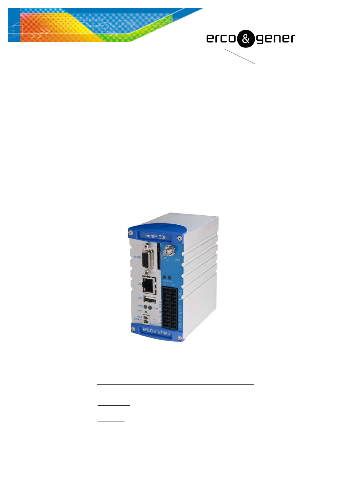
3 General presentation
3.1 Description
Description of the GenIP 30i:
Front side
Sub D 9pin/F connector
SMA/F antenna connector
LEDS
Ethernet and LAN Connector
SIM reader
LEDS
USB Connector
Connector
Reset Button - RS485
- VO
- INPUT (Dig/Ana)
- OUTPUT (Dig/Ana)
- GND
Supply Connector
Rear side
DIN-Rail fixing
Cli
p
Descriptions and non-contractual illustrations in this document are given as an indication only.
ERCOGENER reserves the right to make any modifications. Dct_427_02
EG_GenIP30i_1016_UG_004_UK Page 17 / 143
3.2 External connections
3.2.1 Connections
3.2.1.1 Antenna connector
GSM antenna connector:
The GSM antenna connector is SMA female with a 50Ωcharacteristic impedance.
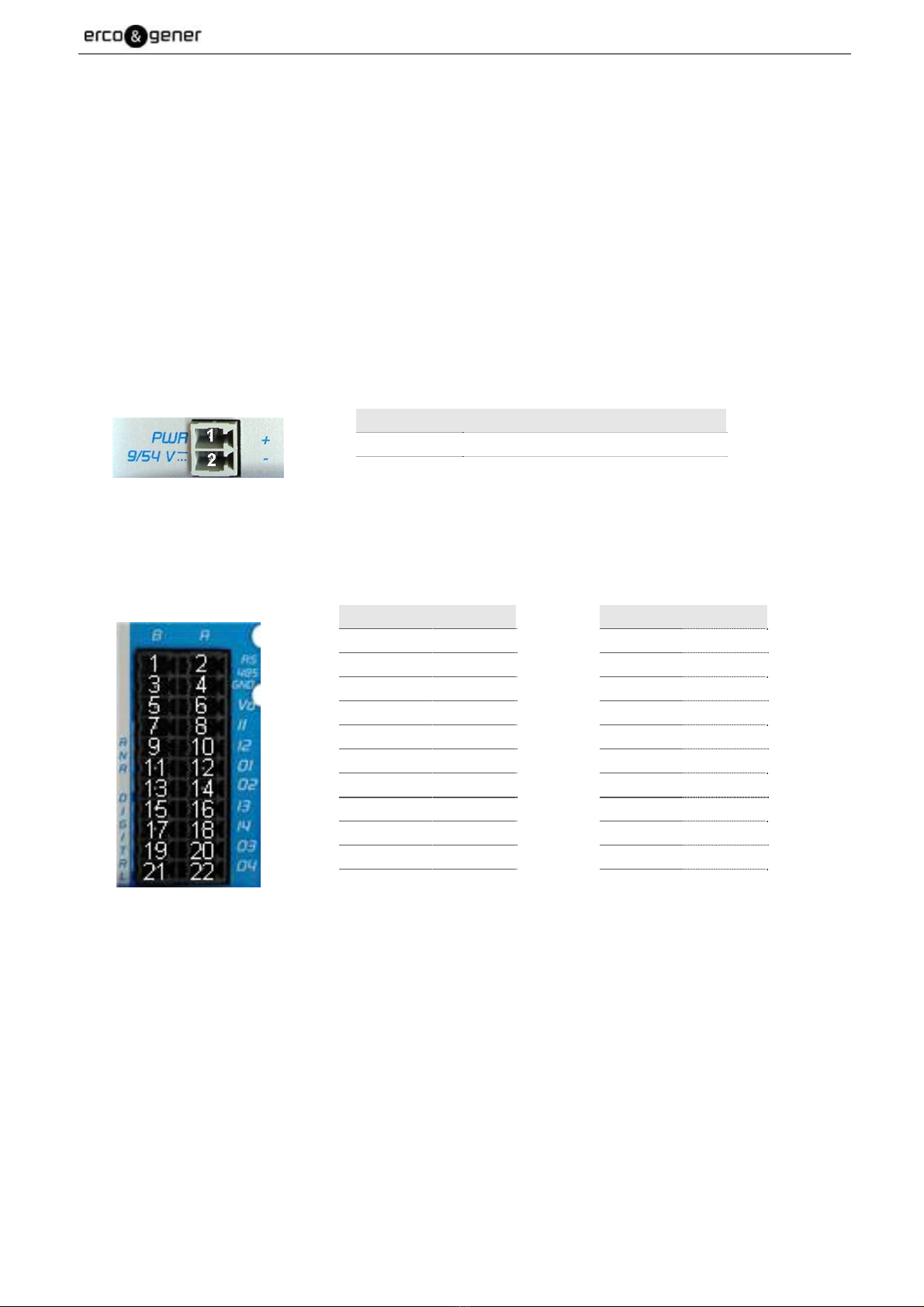
3.2.1.2 Screw connectors
Screw connectors with 2 male pins supply 9/54VDC:
This connector is for the power supply.
Pin N° Signal
1 + VDC
2 - GND
Pluggable connection with 22 male pins:
This connector of the GenIP 30i is a connector for the RS485, the digital and analog Inputs/Outputs.
Pin N° Signal Pin N° Signal
1 RS485 B– 2 RS485 A+
3 GND 4 GND
5 GND
6 VO
7 GND
8 I1
9 GND
10 I2
11 O1-
12 O1+
13 O2-
14 O2+
15 GND
16 I3
17 GND
18 I4
19 O3-
20 O3+
21 O4-
22 O4+
Descriptions and non-contractual illustrations in this document are given as an indication only.
ERCOGENER reserves the right to make any modifications. Dct_427_02

EG_GenIP30i_1016_UG_004_UK Page 18 / 143
3.2.1.3 Sub D 9-pin connector
The Sub D 9-pin female connector is used for the RS232 serial link connection.
Pin N° Description Circuit (V24 – RS232C) I/O
1 Signal detection 109 – DS – DCD O
2 Data reception 104 – RD – RXD O
3 Data transmission 103 – ED – TXD I
4 Data terminal ready 108/2 – TDP – DTR I
5 Signalization ground 102 – TS – GND -
6 Data set ready 107 – PDP – DSR O
7 Request to send 105 – DPE – RTS I
8 Clear to send 106 – PAE – CTS O
9 Ring indicator 125 – IA – RI O
By default, all the outgoing signals are in high level. To dialog with the GenIP 30i, only the TXD, RXD and
ground signals are essential. The other signals are not necessary.
3.2.1.4 RJ45 Ethernet LAN connector
The RJ45 connector is used for the Ethernet LAN connection. The LAN speed is 100 Mbits.
GenIP 30i accepts straight or crossed Ethernet cables.
Status of the connector leds
Action LED Status
At powering ON Green and yellow OFF
When LAN is electrically connected Yellow Fixed
Exchanges of information on LAN Green Flashing
1 8 Pin N° Signal
1 TD+
2 TD-
3 RD+
4 CT
5 CT
6 RD-
7 NC
8 GND
Descriptions and non-contractual illustrations in this document are given as an indication only.
ERCOGENER reserves the right to make any modifications. Dct_427_02

EG_GenIP30i_1016_UG_004_UK Page 19 / 143
3.2.1.5 USB connectors
The GenIP 30i provides 2 connectors.
Pin name Signal
1 Power +5V (VBUS) 500mA max.
2 Data (D-)
3 Data (D+)
4 Ground (GND)
3.2.1.6 Reset Button
The "Reset" button is situated under the 2 LEDS "PWR" and "CONF".
It can be pressed thanks to an accessory of a diameter < 2mm (paperclip for example)
This button has two functions:
•Reloading the factory configuration,
•Reloading the reference configuration.
Procedure for reloading the factory configuration:
•Turn the GenIP 30i OFF,
•Press the Reset button,
•Turn the GenIP 30i ON,
•Wait 30 seconds before the CONF led flashes and the GSM led turns ON or flashes.
•Release the Reset button,
•Wait PWR fixed and after blinked
•From now on, the factory parameters are reloaded.
Procedure for reloading the reference configuration:
To work, there must have been a reference configuration saved in the GenIP 30i.
If there was no reference configuration saved, then the factory configuration will be loaded.
•The GenIP must be powered ON and the Power led must be flashing,
•Press during 5 seconds the Reset button,
•After a few seconds, the led Power is fixed.
•Release the button
•Then the Power led flashes, indicating that the procedure is now finished,
•From now on, the GenIP 30i has reloaded the reference configuration parameters (IP address,
mask...).
Descriptions and non-contractual illustrations in this document are given as an indication only.
ERCOGENER reserves the right to make any modifications. Dct_427_02
EG_GenIP30i_1016_UG_004_UK Page 20 / 143
3.2.2 Accessories supplied
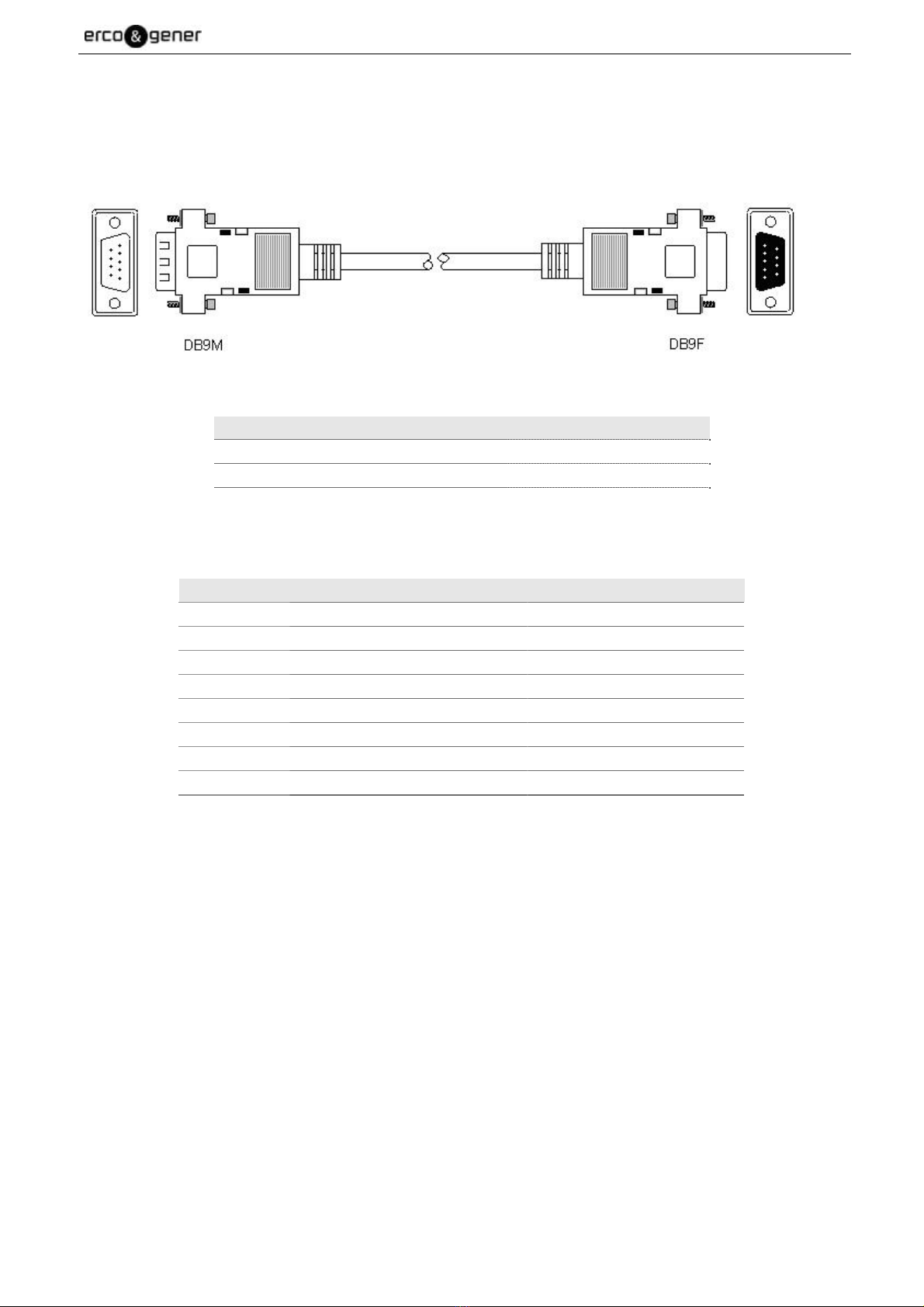
3.2.2.1 Straight cable 9pin M/F
The straight cable 9pin M/F allows to dialog via the RS232.
Component Characteristics
Straight cables 9pin Male/Female Length ≈2m
9 wires
Lockings
Pin N° Designation Circuit (V24 – RS232C)
1 Signal detection 109 – DS – DCD
2 Data reception 104 – RD – RXD
3 Data transmission 103 – ED – TXD
4 Data terminal ready 108/2 – TDP – DTR
5 Signalization ground 102 – TS – GND
6 Data set ready 107 – PDP – DSR
7 Request to send 105 – DPE – RTS
8 Clear to send 106 – PAE – CTS
9 Call indicator 125 – IA – RI
Descriptions and non-contractual illustrations in this document are given as an indication only.
ERCOGENER reserves the right to make any modifications. Dct_427_02
Table of contents
Popular Network Router manuals by other brands


XAVI Technologies Corp.
XAVI Technologies Corp. X7721r user manual

JCG
JCG Q8 quick start guide

Telebyte
Telebyte 458-LM-A1-30 manual

Cisco
Cisco 805 Series quick start guide

Planet Networking & Communication
Planet Networking & Communication igs-801m user manual

Fujitsu
Fujitsu BroadOne LS110 Residential Femtocell user guide

AYRSTONE
AYRSTONE AyrMesh Setup manual

TRENDnet
TRENDnet TW100-BRM504 Quick installation guide

LevelOne
LevelOne PLI-2030 user manual

Omnitron Systems Technology
Omnitron Systems Technology iConverter 4GT user manual

Asus
Asus RT-ACRH12 quick start guide

Optical Systems Design
Optical Systems Design OSD2524 quick start guide