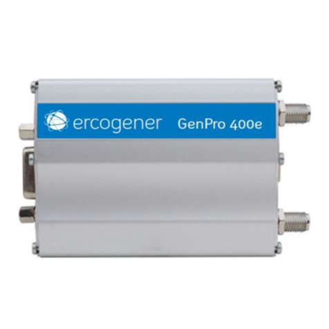
Ercogener GenPro 400e User manual

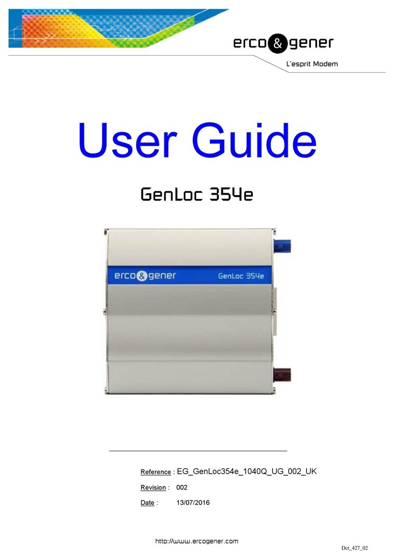
User Guide
GenPro 400e
Reference : EG_GenPro400e_1103_UG_001_UK
Revision : 001 Id : 3900
Date : december 2019
http://www.ercogener.com
Dct_427_02

EG_GenPro400e_1103_UG_001_UK
Page 2 / 46
Descriptions and non-contractual illustrations in this document are given as an indication only.
ERCOGENER reserves the right to make any modifications. Dct_427_02
Document History
Rev.
Modifications
Author
Date
Validation
Date
000
Creation
YST
04/04/2019
DJE
04/04/2019
001
Information update
PGL
03/12/2019
LGO
06/12/2019
The main modifications of this document compared to the previous version are easily identifiable on a screen
by the blue color of the text.

EG_GenPro400e_1103_UG_001_UK
Page 3 / 46
Descriptions and non-contractual illustrations in this document are given as an indication only.
ERCOGENER reserves the right to make any modifications. Dct_427_02
TABLE OF CONTENTS
PRESENTATION............................................................................................................................................... 6
WARNING ......................................................................................................................................................... 7
COPYRIGHT ..................................................................................................................................................... 8
SYMBOLS USED.............................................................................................................................................. 8
1SECURITY RECOMMANDATIONS......................................................................................................... 9
1.1 GENERAL SECURITY ........................................................................................................................... 9
1.2 SECURITY IN A VEHICLE .................................................................................................................... 10
1.3 CARE AND MAINTENANCE.................................................................................................................. 10
1.4 YOUR RESPONSIBILITY...................................................................................................................... 10
2DESCRIPTION........................................................................................................................................ 11
2.1 CONTENT......................................................................................................................................... 11
2.2 MODEM PACKAGING ......................................................................................................................... 11
2.3 MECHANICAL CHARACTERISTICS....................................................................................................... 12
2.3.1 Fixing brackets......................................................................................................................... 12
2.4 CHARACTERISTICS AND SERVICES .................................................................................................... 13
2.4.1 Services .................................................................................................................................... 13
2.4.2 Interfaces.................................................................................................................................. 13
2.5 ENVIRONMENTAL CHARACTERISTICS ................................................................................................. 14
3INTERFACES AND CONNECTIONS..................................................................................................... 15
3.1 FRONT SIDE...................................................................................................................................... 15
3.2 BACK SIDE ....................................................................................................................................... 16
3.3 FUNCTIONAL ARCHITECTURE............................................................................................................. 16
3.3.1 General...................................................................................................................................... 16
3.4 POWER SUPPLY................................................................................................................................ 17
3.4.1 Power supply cables ............................................................................................................... 17
3.4.2 Power supply............................................................................................................................ 17
3.4.3 Consumptions.......................................................................................................................... 18
3.4.3.1 Power supply dimensioning .......................................................................................... 19
3.5 SERIAL LINK RS232C ...................................................................................................................... 20
3.6 USB SERIAL LINK............................................................................................................................. 21
3.6.1 Standard.................................................................................................................................... 21
3.6.2 Installation of USB drivers...................................................................................................... 22
3.6.3 Modem diagnostic ................................................................................................................... 22
3.6.4 Using the modem with the USB port ..................................................................................... 23
3.6.5 Local network connection....................................................................................................... 24
3.7 AUDIO CHANEL................................................................................................................................. 25

EG_GenPro400e_1103_UG_001_UK
Page 4 / 46
Descriptions and non-contractual illustrations in this document are given as an indication only.
ERCOGENER reserves the right to make any modifications. Dct_427_02
3.7.1 Synoptic of audio string.......................................................................................................... 25
3.7.2 Microphone input MIC+ et MIC-.............................................................................................. 26
3.7.3 Loudspeaker output SPK+ and SPK-..................................................................................... 27
3.8 RESET............................................................................................................................................ 28
3.9 CARTE SIM...................................................................................................................................... 29
3.10 LEDS OF THE MODEM........................................................................................................................ 29
4GSM EXTERNAL ANTENNA................................................................................................................. 31
4.1 EXTERNAL ANTENNA ASSEMBLY........................................................................................................ 32
5USE OF THE MODEM............................................................................................................................ 33
5.1 SPECIFIC RECOMMENDATIONS FOR THE USE OF THE MODEM IN VEHICLES............................................ 33
5.1.1 Recommended connection on the battery of a truck........................................................... 33
5.2 TURNING THE MODEM OFF ............................................................................................................... 33
5.3 TURNING THE MODEM ON................................................................................................................. 33
5.4 MODE POWER SAVING CONTROL (POWER OFF) ................................................................................ 34
5.5 CTS SIGNAL..................................................................................................................................... 34
5.6 RTS SIGNAL .................................................................................................................................... 35
5.7 RI SIGNAL........................................................................................................................................ 35
5.8 STARTING WITH THE MODEM.............................................................................................................. 36
5.8.1 Mounting the modem............................................................................................................... 36
5.8.2 SIM card installation................................................................................................................ 36
5.9 USE THE MODEM............................................................................................................................... 37
5.9.1 Checking the communication with the modem .................................................................... 37
5.9.2 Using the documentation of AT command list ..................................................................... 37
5.10 VERIFICATION OF THE PIN CODE ....................................................................................................... 38
5.11 CHECKING THE LEVEL AND QUALITY OF THE RF RECEIVING SIGNAL................................................... 38
5.11.1 Response with modem attached to 2G network .............................................................. 39
5.11.2 Response with modem attached to 3G network .............................................................. 39
5.11.3 Response with modem attached to 4G network .............................................................. 39
5.12 VERIFICATION OF MODEM REGISTRATION ON CELLULAR NETWORK...................................................... 40
5.12.1 AT+CREG? command ......................................................................................................... 40
5.12.1.1 Chronology of answers to commands AT+CREG? ..................................................... 40
5.12.1.2 Operator selection command AT+COPS?.................................................................... 40
5.12.2 AT+CGREG? command ...................................................................................................... 41
5.12.2.1 Chronology of answers to commands AT+CGREG? .................................................. 41
5.12.3 AT+CEREG? command....................................................................................................... 41
5.12.3.1 Chronology of answers to commands AT+CEREG?................................................... 41
5.13 MAIN AT (HAYES) COMMANDS........................................................................................................ 42
6RECOMMENDED ACCESSORIES........................................................................................................ 43
7CUSTOMER SUPPORT......................................................................................................................... 43

EG_GenPro400e_1103_UG_001_UK
Page 5 / 46
Descriptions and non-contractual illustrations in this document are given as an indication only.
ERCOGENER reserves the right to make any modifications. Dct_427_02
ANNEX 1 –4 PINS MICRO FIT CABLE 2 WIRES WITHOUT FUSE ............................................................ 44
ANNEX 2 –USB 2.0 CABLE TYPE A MALE / TYP MINI B MALE ............................................................... 45
ANNEX 3 –RF CHARACTERISTICS............................................................................................................. 45
EG_GenPro400e_1103_UG_001_UK
Page 6 / 46
Descriptions and non-contractual illustrations in this document are given as an indication only.
ERCOGENER reserves the right to make any modifications. Dct_427_02
Presentation
Entirely dedicated to Machine à Machine (M2M) applications and embedded data services, the modem
GenPro 400e combines the GSM/GPRS/UMTS/HSPA/LTE functions in the same robust casing.
The bands supported by the modem are:
Table 1 : Bands supported by the modem
4G LTE
3G UMTS/HSDPA/HSUPA
2G GSM/GPRS/EDGE
3GPP Release 9
Long Term Evolution (LTE)
Evolved Uni. Terrestrial Radio Access
(E-UTRA)
Frequency Division Duplex (FDD)
DL Multi-Input Multi-Output (MIMO) 2
x 2
3GPP Release 8
Dual-Cell HS Packet Access (DC-
HSPA+)
UMTS Terrestrial Radio Access
(UTRA)
Frequency Division Duplex (FDD)
DL Rx diversity
3GPP Release 8
Enhanced Data rate GSM Evolution
(EDGE)
GSM EGPRS Radio Access (GERA)
Time Division Multiple Access (TDMA)
DL Advanced Rx Performance Phase
1
•Band 20 (800 MHz)
•Band 5 (850 MHz)
•Band 8 (900 MHz)
•Band 3 (1800 MHz)
•Band 1 (2100 MHz)
•Band 7 (2600 MHz)
•Band 5 (850 MHz)
•Band 8 (900 MHz)
•Band 2 (1900 MHz)
•Band 1 (2100 MHz)
•GSM 850 MHz
•E-GSM 900 MHz
•DCS 1800 MHz
•PCS 1900 MHz
See also ANNEX 3 - RF characteristics
The protocols of IP connectivity integrated in the GenPro 400e allow the quick installation of embedded
telematics solutions with strong added-value.
This document describes the modem and provides the following information:
- General presentation,
- Functional description,
- Available basic services,
- Installation and use of the modem (first level),
- Recommended accessories for the use of the modem.
When migrating a product to the GenPro 400e, check the initialization strings.
There may be some variations
For more information about this document, ERCOGENER puts at your disposal the following elements:
- Instruction sheet
- User guide
- AT Commands List (for the modem TOBY L210)
- Certificate of Origine, Conformity …
- Drivers
- Client Support (Hot-Line)
These different documents are available on our website www.ercogener.com in the download
area of the product concerned.
To access the download area of our products (documentation, drivers, tools ..) log in to the
"Pro" area.

EG_GenPro400e_1103_UG_001_UK
Page 7 / 46
Descriptions and non-contractual illustrations in this document are given as an indication only.
ERCOGENER reserves the right to make any modifications. Dct_427_02
Warning
The GenPro 400e is dedicated to 'Machine To Machine' (M2M) applications only.
ercogener recommends the use of SIM card subscriptions of the 'Machine To Machine'
(M2M) type.
Video, VoIP (Voice over IP) transfer requires the payment of additional royalties.
•ercogener recommends to read carefully all documents linked to the product GenPro 400e that can be
download on our website www.ercogener.com.
•ercogener cannot be held responsible for:
- The problems due to an inappropriate use of the GenPro 400e.
- The problems due to a wrong configuration
- The dysfunctions due to the absence, a bad coverage or termination of the cellular networks
services.
- The dysfunctions if the product is used for the watching of physical persons where human life is
engaged.
•ercogener reserves the right to modify the functions of its products "GenPro 400e" without previous
notice.
- To avoid any risk of electrocution, do not open the casing.
- For any functioning, the casing must be closed.
- No internal part can be repaired by the user. The GenPro 400e must be returned to the factory for any
repair with RMA request (Retour Matériel Accepté).
- The GenPro 400e must be placed in a normally ventilated area, out of sources of heat.
- In order to guarantee the electromagnetic compatibility, the length of the serial cable, the power supply
cable and the inputs/outputs cable must not exceed 3 meters.
- The GenPro 300e must not be connected directly to the mains supply (230 VAC); a voltage adapter must be
used. The GenPro 400e must not be connected directly to the mains supply; a voltage adapter must be
used PS1 (max 15W).
This marking on the product, accessories, packaging or literature indicates that the product
and its electronic accessories (e.g. cable etc.) should not be disposed of with other household
waste.

EG_GenPro400e_1103_UG_001_UK
Page 8 / 46
Descriptions and non-contractual illustrations in this document are given as an indication only.
ERCOGENER reserves the right to make any modifications. Dct_427_02
Copyright
The reproduction, transfer, distribution or storage of part or the totality of the contents of this document, in
any form, without the prior written authorization of ercogener is strictly prohibited.
GenPro 400e is a trademark of ercogener.
Hayes is a registered trademark of Hayes Microcomputer Product Inc. The names of products and
companies mentioned in this document may be names or trademarks of their respective holders.
The use of some products or services described in this document may require a paying subscription. The
availability of some products or services described in this document may change, depending on the
configurations and the materials.
In some countries, restrictions of use of the devices may be applied. For more information, thank you to
contact your nearest legally qualified local government representative.
ercogener follows a method of continuous development. Consequently, ercogener reserves the right to
change and improve any of its products described in this document, without notice.
The contents of this document are provided “as it is”. Except for the applicable obligatory laws, no guarantee
in any form, explicit or implicit, including but without being limited to it the implicit guarantees of aptitude to
marketing and of appropriateness to a particular use, is granted concerning the precision, the liability or the
contents of this document. ercogener reserves the right to revise or withdraw this document at any time and
without notice.
ercogener cannot be held responsible for any loss of data or income, as well as particular
damage, incidental, consecutive or indirect.
Symbols used
The following symbols are used to highlight the important information of this document.
A symbol for the essential information concerning the module integration and performance.
A warning symbol indicates the actions that could harm or damage the module.

EG_GenPro400e_1103_UG_001_UK
Page 9 / 46
Descriptions and non-contractual illustrations in this document are given as an indication only.
ERCOGENER reserves the right to make any modifications. Dct_427_02
1 Security recommandations
1.1 General security
It is important to respect the specific regulations linked with the use of radio equipment, in particular with the
possible risks of interference due to radio frequency (RF). Please respect carefully the following security
recommendations.
Turn OFF your GSM modem:
●On an aircraft, the use of cellular telephones can endanger the plane operations; disturbing the
cellular network is illegal. The non-observance of this instruction can lead to the suspension or the
exclusion of the cellular phone services, or even to a trial, or both,
●At a refueling station,
●In any area with a potential explosive atmosphere that could cause an explosion or a fire,
●In hospitals and other places where medical equipment may be used.
Restrictions of use of radio equipment in places where signs indicate that the use of cellular phones is
prohibited or dangerous.
There can be a danger associated with the use of your GSM modem close to insufficiently protected medical
equipment such as audio devices and pacemakers.
Consult the manufacturers of medical equipment to know if it is adequately protected.
Using your GSM modem close to other electronic equipment may also cause interferences if the equipment
is insufficiently protected.
Pay attention to the warnings and the recommendations of the manufacturers.
The modem is designed to be used with "fixed" and "mobile" applications:
▪“Fixed" application: The GSM modem is physically linked to a site and it is not possible to move it
easily to another site.
▪"Mobile" application: The GSM modem is designed to be used in various places (other than fixed) and
is intended to be used in portable applications.
▪The modem must be used at more than 20cm from the human body.
This equipment is powered at a Very Low Security Voltage and at non-dangerous energy level PS1 (max
15W).

EG_GenPro400e_1103_UG_001_UK
Page 10 / 46
Descriptions and non-contractual illustrations in this document are given as an indication only.
ERCOGENER reserves the right to make any modifications. Dct_427_02
1.2 Security in a vehicle
Respect the national regulations linked with the use of cellular telephones in vehicles. Road safety is always
a priority.
An incorrect installation of the GSM modem in a vehicle could cause an incorrect functioning of the vehicle’s
electronics. To avoid such problems, make sure that the installation was done by a qualified person. During
the installation, a verification of the electronic protection system of the vehicle must be done.
The use of warning equipment that activates the headlights or the horn of a vehicle on a public highway is
not authorized.
1.3 Care and maintenance
The following suggestions will help you to preserve this product for many years.
Do not expose the modem to the extreme environments, to high temperature or high humidity.
Do not use or store the modem in dusty or dirty places, it could be damaged.
Do not try to disassemble the modem, at the risk of cancelation of the guarantee.
Do not expose the modem to water, rain or spilled beverage, it is not impermeable.
Avoid dropping, striking, or shaking the modem violently. The lack of care can damage it.
Do not place the modem next to computer disks, credit or travel cards or other magnetic supports. The
information contained on disks or cards can be affected by the modem.
The use of other equipment or accessories not made or not authorized by ercogener can cancel the warranty
of the modem.
1.4 Your responsibility
This modem is under your responsibility. Treat it with care, it is not a toy. Keep it always in a secure place
and out of the reach of children.
Try to remember your PIN and PUK codes. Familiarize yourself with the modem and use the security
functions to lock it in case of non-authorized use or in case of theft.

EG_GenPro400e_1103_UG_001_UK
Page 11 / 46
Descriptions and non-contractual illustrations in this document are given as an indication only.
ERCOGENER reserves the right to make any modifications. Dct_427_02
2 Description
2.1 Content
The GenPro 400e is supplied with:
- a GenPro 400e cardboard packaging,
- a modem GenPro 400e,
- 2 fixing brackets,
- a power supply cable 2-wires (Red/Black) stripped without fuse
- Cable USB 2.0 Type A / mini B
- a technical sheet (Instructions Sheet).
Figure 1 : Content
2.2 Modem packaging
The external dimensions of the modem packaging are:
- Width ..................: 110 mm,
- Height.................: 55 mm,
- Length ................: 68 mm.
- Weight ................: 172 g

EG_GenPro400e_1103_UG_001_UK
Page 12 / 46
Descriptions and non-contractual illustrations in this document are given as an indication only.
ERCOGENER reserves the right to make any modifications. Dct_427_02
2.3 Mechanical characteristics
Table 2 : Mechanical characteristics
Dimensions
73 x 54.5 x 25.5 mm (connectors excluded)
Complete dimensions
104 x 92 x 40 mm
Weight
≈ 90 grams (modem only)
< 152 grams (modem modem + brackets + cables)
Volume
101.5 cm³
Casing
Aluminium profile
Waterproof level
IP31
The illustration below shows the dimensions of the modem including the clearances necessary for the
installation of the modem.
Figure 2 : Dimensions and clearances
2.3.1 Fixing brackets
2 brackets to fix the modem on a support.
Figure 3 : Back side with fixing brackets
Left
fixing
bracket
Right
fixing
bracket

EG_GenPro400e_1103_UG_001_UK
Page 13 / 46
Descriptions and non-contractual illustrations in this document are given as an indication only.
ERCOGENER reserves the right to make any modifications. Dct_427_02
2.4 Characteristics and Services
2.4.1 Services
The GenPro 400e incorporates a GSM / GPRS / EDGE modem (Class 12), UMTS HSPDA (Cat.24), HSUPA
(Cat.6) and 4G-LTE (Cat.4). It is intended for asynchronous transmission of binary data and SMS.
Table 3 : Characteristics and networks
4G LTE
3G UMTS/HSDPA/HSUPA
2G GSM/GPRS/EDGE
Data rate
•LTE category 4: up to 150 Mbit/s
DL, 50 Mbit/s UL
Data Rate
•HSDPA cat.24, up to 42 Mbit/s DL
•HSUPA cat.6, up to 5.6 Mbit/s UL
Data Rate5
•GPRS multi-slot class 12, CS1-
4,up to 85.6 kbit/s DL/UL
•EDGE multi-slot class 12, MCS1-9,
up to 236.8 kbit/s DL/UL
Table 4 : Bands and services of the different networks
LTE
Cat 4 (150 Mbit/s DL, 50 Mbit/s UL
3GPP Release 9
FDD Bands :
1, 3, 5, 7, 8, 20 (EU/Asia/Africa)
All channel bandwidths : 1.4-20 MHz
MIMO 2x2
UMTS/DC-HSPA+
Bands (in MHz)
850/900/1 900/2 100
42 Mbit/s downlink, 5.76 Mbit/s uplink
Rx diversity
GSM
Bands (in MHz)
850/900/1 800/1 900
GPRS & EDGE Class 12
SMS
MT/MO PDU / Text mode
SMS over IMS and via SMS-C
Voice
CSFB
Code : HR/FR/EFR/AMR/AMR-WB
Echo cancelation & noise reduction
See also ANNEX 3 - RF characteristics
2.4.2 Interfaces
Interfaces
• 2 GSM antennas: 2 SMA-Female connectors
• Power supply : +7.2 to +32 VDC (4-pin micro-FIT connector)
• 1 serial port RS232 (300 to 115200bds) Sub-D 15 pins female
• 1 USB port
• Commandes AT : GSM 07.05 et 07.07
• SIM reader format mini SIM 2FF (SIM 3V –1,8V)
Options / additional accessories (*)
• DIN-rail kit K002
• Recommanded antenna 636Z232160 (include only one antenna)
For another antenna solution, please contact ercogener
• Waterproof casing K011
• Accessories: cables, power supplies... (information available on our website)
(*)These options can be in addition or can replace some functions, contact us.
(see § 3.3 Functional architecture)

EG_GenPro400e_1103_UG_001_UK
Page 14 / 46
Descriptions and non-contractual illustrations in this document are given as an indication only.
ERCOGENER reserves the right to make any modifications. Dct_427_02
2.5 Environmental characteristics
To ensure a correct operation of the Modem, the specific limits described in the table below must be
respected
Table 5 : Environmental characteristics
Operating temperature range
-20 °C à +60 °C
Storage temperature range
-40 °C à +85 °C
Operating humidity without condensation
HR < 70% @ +55°C
Atmospheric pressure
700 hPa à 1060 hPa (-400 m à 3000 m)

EG_GenPro400e_1103_UG_001_UK
Page 15 / 46
Descriptions and non-contractual illustrations in this document are given as an indication only.
ERCOGENER reserves the right to make any modifications. Dct_427_02
3 Interfaces and connections
3.1 Front side
Figure 4 : Front side
See ANNEX 1 –4 pins Micro Fit cable 2 wires without fuse
Table 6 : Front side connection
Micro Fit 4 points
Sub-HD 15 points
Mini USB
1
No Connected
1
No Connected
1
+VUSB
2
No Connected
2
Data transmission
2
Data D-
3
GND
3
No Connected
3
Data D+
4
+VDC
4
Microphone +
4
Non connecté
5
Microphone -
5
GND
6
Data reception
6
Loudspeaker + (*)
7
Data set ready
7
Loudspeaker - (*)
8
Data terminal ready
8
Not connected
9
Signalization ground
9
Microphone - (*)
10
Loudspeaker +
10
Microphone + (*)
11
Ready to send
12
Request to send
13
Call indicator
14
Reset
15
Loudspeaker -
For more informations on the signals cf § 3.5 Serial link RS232C.
* Please consult us for audio access on the mini USB connector..
Connector
Micro-Fit 4pts/M
Connector
Sub HD 15pts/F
Connector
Mini USB

EG_GenPro400e_1103_UG_001_UK
Page 16 / 46
Descriptions and non-contractual illustrations in this document are given as an indication only.
ERCOGENER reserves the right to make any modifications. Dct_427_02
3.2 Back side
Figure 5 : Back side
Antenna connectors are female SMA type with 50Ω impedance.
3.3 Functional architecture
3.3.1 General
Figure 6 : Functional architecture
Connector
SMA-F MAIN
GSM Antenna
GSM LED
SIM card cover
Connector
SMA-F auxiliary
GSM Antenna

EG_GenPro400e_1103_UG_001_UK
Page 17 / 46
Descriptions and non-contractual illustrations in this document are given as an indication only.
ERCOGENER reserves the right to make any modifications. Dct_427_02
3.4 Power supply
3.4.1 Power supply cables
The modem is powered with the cable supplied with the equipment (cf ANNEX 1 –4 pins Micro Fit cable 2
wires without fuse).
Table 7 : Description of power supply pins
Signal
Connector 4 pins
Pins N°
I/O
Kind of I/O
Description
+VDC
GND
4
3
E
Power supply
Power supply
Corresponds to wires
Red pour +VDC
Black pour GND
The pins 1 and 2 are not used The power supply to the modem is done only via the pins 4
(+VDC) and 3 (GND).
3.4.2 Power supply
The modem must be powered by an external DC voltage between +7.2VDC and +32VDC
The internal regulation is done by a DC/DC converter and allows the supply of all necessary internal DC
voltages.
The modem is also internally protected against voltage peaks of more than 32 VDC.
The following table describes the consequences of an overvoltage or drop of voltage on the modem.
Table 8 : Effects of power supply defect
Then :
▪Voltage falls below 7.2V
▪The functioning and the GSM communication are
not guaranteed.
▪Voltage above 32V (Punctual
peaks)
▪The modem guarantees its own protection.
▪Voltage above 32V (Continuous
overvoltage)
▪The modem is protected by the fuse assembled on
the power supply cable.

EG_GenPro400e_1103_UG_001_UK
Page 18 / 46
Descriptions and non-contractual illustrations in this document are given as an indication only.
ERCOGENER reserves the right to make any modifications. Dct_427_02
3.4.3 Consumptions
Table 9 : Power supply range
Power supply range
7.2VDC to 32VDC
Table 10 : Consumption with Shut down mode
Shuts down
IMOY NOM.
Unit.
VIN
7.2
12
24
32
VDC
IMOY NOM.
0.52
0.45
0.32
0.3
mA
The GenPro 400e is in 'Shuts down' mode with the command AT+CPWROFF and the serial port RS232C
and USB disconnected.
Table 11 : Consumption with Power Saving mode
Power Saving
IMOY MAX.
Unit.
VIN
7.2
12
24
32
VDC
2G
GSM / GPRS
2.45
1.7
1
0.9
mA
3G
UTRAN HSDPA HSUPA
4.3
2.8
1.6
1.2
mA
4G
LTE
8.3
5.5
3
2.3
mA
The GenPro 400e is attached to network in power saving mode with command AT+UPSV=1 without data
transfer and serial port RS232C and USB disconnected
RS232C and USB : an additional consumption can appear depending on signal levels
connected on serial connexion.
Table 12 : Consumption with data transfer mode
Unit
VIN
7.2
12
24
32
V
2G
Peak current
1820
900
410
310
mA
Average
240
140
65
49
mA
3G
Maximum
370
215
110
85
mA
Average
310
175
95
75
mA
LTE
Maximum
470
270
130
100
mA
Average
250
180
60
45
mA

EG_GenPro400e_1103_UG_001_UK
Page 19 / 46
Descriptions and non-contractual illustrations in this document are given as an indication only.
ERCOGENER reserves the right to make any modifications. Dct_427_02
3.4.3.1 Power supply dimensioning
The below graph shows the maximum peak current. The power supply must be able to supply this current
during the GSM "Burst"
Figure 7 : Max consumption
This consumption is not permanent. It corresponds to the burst consumption during 2G GSM
communications.
0
500
1000
1500
2000
0 5 10 15 20 25 30 35
IMAX (mA)
VIN (V)

EG_GenPro400e_1103_UG_001_UK
Page 20 / 46
Descriptions and non-contractual illustrations in this document are given as an indication only.
ERCOGENER reserves the right to make any modifications. Dct_427_02
3.5 Serial link RS232C
The serial links RS232C and USB cannot work simultaneously.
Table 13 : Description of pins of serial link RS232C
Signal
Connector
Sub-HD 15 pints
Pins N°
I/O
RS232
standards
Description
CT103 / TX
2
I
TX
Data transmission
CT104 / RX
6
O
RX
Data reception
CT107 / DSR
7
O
DSR
Data set ready
CT108-2 / DTR
8
I
DTR
Data terminal ready
CT106 / CTS
11
O
CTS
Ready to send
CT105 / RTS
12
I
RTS
Request to send
CT125 / RI
13
O
RI
Call indicator
GND
9
Ground
Table 14 : Characteristics of serial link RS232C
Characteristics
Symbols
Conditions
Min.
Typ.
Max.
Unité
Input Voltage –Range
VINPUT
Input Voltage –
Range
-25
+25
VDC
Input Voltage –Low
VIL
Input Voltage –Low
0.6
1.1
VDC
Input Voltage –High
VIH
Input Voltage –High
1.5
24
VDC
Input Hysteresis
VHys
Input Hysteresis
0.5
VDC
Input Resistance
Rin
Input Resistance
3
5
7
KΩ
Output Voltage
VOUT
All transmitter
outputs loaded with
3 kΩ to ground
±5
±5.4
VDC
Transmitter Output
Resistance
ROUT
300
50k
Ω
RS-232 Output Short-Circuit
Current
ICC
±60
mA
Figure 8 : Standards signals of serial link RS232C
Other manuals for GenPro 400e
1
This manual suits for next models
1
Table of contents
Other Ercogener Modem manuals

Ercogener
Ercogener GenIP 30i User manual

Ercogener
Ercogener GenPro 400e User manual

Ercogener
Ercogener GenPro 25e User manual

Ercogener
Ercogener GenPro 425e User manual

Ercogener
Ercogener GenPro 300e User manual

Ercogener
Ercogener GenLoc 354e User manual

Ercogener
Ercogener GenPro 425e User manual

Ercogener
Ercogener GenPro 25e User manual