Erduro BTS ENGINEERING Fluid Solutions BTKF-I User manual

SINGLE STAGE
USER MANUAL
BTKF-I
https://prom-nasos.pro
https://bts.net.ua https://
prom-nasos.com.ua
+38 095 656-37-57,
+38 067 360-71-01,
+38 063 362-12-31,

- You should absolutely obey the followng safety nstructons.
- Never touch the pump and ppes havng temperature more than 80 ºC. Necessary
precautons should be taken for warnng users. (E.g Warnng sgns and sgnboards )
-
Never operate pump n reverse
drecton.
- Do not walk over pump pr ppes whch are connected to pump.
- Any operaton whch wll be done n pump should be performed by at least two
staffs.
- No works should certanly be done over wthout stoppng pump group.
-
Power comng to pumps should be off and you should be sure that t wll not operate
agan before you make any work
- Absolutely nstall the safety guards whch were dsmounted before after work n
pump has finshed.
- Tensons and crcks n ppe system absolutely should not reach to pump.
-
Do not make any operaton whle pump and ppes whch are connected to pump are
under pressure.
- Cloths of personnel who wll work over should be sutable and/or they should use
safety equpments.
-
Never do any operatons when pump s stll hot.
- Electrcal connecton related wth pump and auxlary equpments should be sutable
wth local rules and made by authorzed personnel.
- Operate pump wth only specfied condtons.
- Do not nsert your hand and fingers nto holes and spaces over pump body.
- Be always careful whle workng wth pumps dschargng hazardous lquds.
SAFETY INSTRUCTIONS
Fl uid
So lut ion s
2

BTKF-I Seres Pumps are centrfugal pumps havng horzontal shaft, separable radal
body, are sngle staged, scroll cased has closed mpellor, and can be connected to
straght ppe.
Usage Areas of Motor Water Pump
Pumps are sutable for dschargng lquds whch are low vscose, whose flow
temperature s up to 110ºC and whch are clean or a lttle drty. (Max20mg/dm³) . In
addton to others; man applcaton areas are:
- Heatng and Coolng Systems
- Water Supply
- Fre Extngushng Plants
- Water Supply and Crculaton Systems n Industral Plants
Explanaton of Pump Codes
BTKF-I 40/200
Pump Type
Rated Dameter of Dscharge Flange (DN-mm)
Number of Stages(pece)
Techncal nformaton
Speed : Up to3600 d/d rpm
Dscharge Flange :DN40 …DN200
Sucton
And Dscharge
Flange : TS EN 1092-2,EN 1092-2-EQV /PN16
Operatonal Temperature
:-10ºC…110ºC
Ambent Temperature (Maxmum) :+40ºC
Body Pressure :16 Bars
Isolaton Class
:F
Protecton Class
:IP55
Motor Connecton :3 Phase-380 V-50 Hz
Fl uid
So lut ion s
BTKF-1 SERİES PUMPS
3

Fl uid
So lut ion s
- Check whether all materals n delvery lst are sent. .
- If there s damage durng shppng please notfy ERDURO Shppng Department
and Transportaton company.
-
If there are mssng materals, mmedately nform ERDURO Shppng Department.
-.
Check whether packagng s damaged durng transportaton.
-
Please carefully take out packaged pump and accessores (f any). Check whether
they are damaged durng transportaton.
General warnngs.
Absolutely obey the followng rules durng transportaton.
-. Use proper wooden crane, forklft, or hostng mechansms For unloadng or
loadng wooden cases, packages, boxes and palettes dependng on ther weght and
volume.
-
Wear gloves, hard tp shoes and helmet durng carryng works.
-
Never stay under hostng mechansm whle loadng or unloadng pumps.
Pump and Motor Group Loadng/Unloadng
Before loadng/unloadng pump group please determned the followng propertes.
- Please find the lftng ponts.
- Please consder total weght and centre of gravty.
-
Please consder the packagng external dmensons
-
Durng loadng/unloadng make acceleratng and brakng operatons as t shall not
cause any damage for workng personnel.
- Load lftng capacty should be sutable wth pump and pump group weght.
- You should never stay under or near lfted load.
SHIPPING OF PUMPS
CARRYING
4
Fl uid
So lut ion s
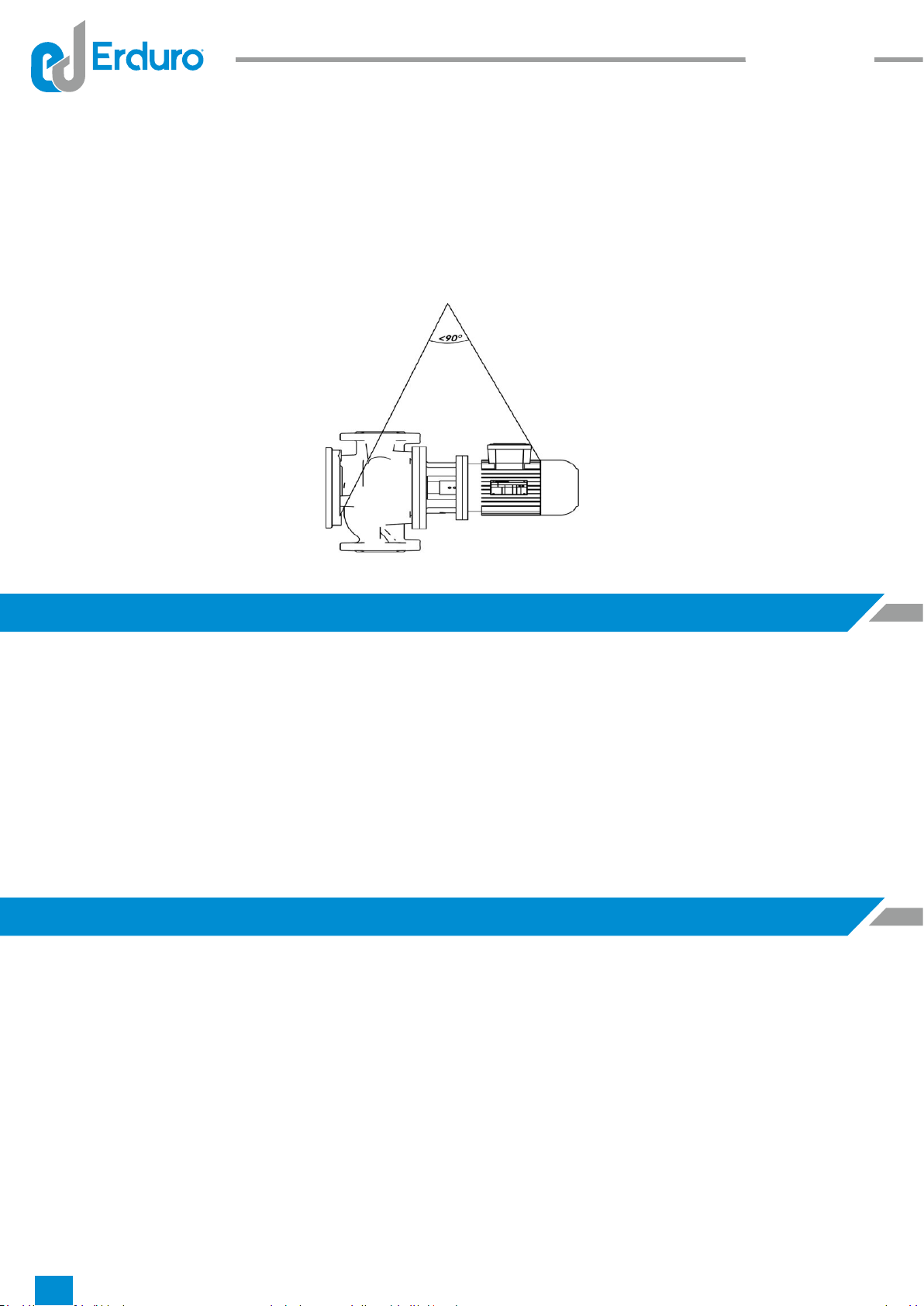
- Pump should be hosted as t s ndcated n Fgure 1 -1 and Fgure 1 -2 for not
causng any damage n pumps. Motor hangng rng should absolutely
not be used
whle lftng complete group.
- Load should be kept n lfted poston more than requred tme.
- Pump and pump group should always be lfted and carred n horzontal poston
Fgure 1 Pump carryng
STORAGE
- If pump group s not mmedately nstalled, t should be stored n a place whch s
clean dry and does not nclude freezng and exploson rsk.
-
If pump bearng are type whch should be greased, they should be extra greased for
preventng entry of mosture to bearngs around shaft
- Pump should be protected from mosture, dust, drt and foregn objects by coverng
wth sutable materal.
- Pump shaft should be rotated a few turns (e.g once a week) for preventng pttng
around pump bearng surfaces and jammng of shaft.
INSTALLATION
Installaton of pump to ts place and connecton setup
and balance should only be
done by expert personnel. Faled nstallaton and pump ground may cause falures.
Ths stuatons are not covered wth warranty
5

Before nstallng the pump n ts place,
Sucton and dscharge flanges should properly be cleaned.
ATTENTION- Pump should be nstalled n a locaton where there s not exploson and
frost hazard and has good ar condtonng.
- There should be enough area around pump for reachng pump easly, for
mantenance and there should be enough space and heght to lft the pump f
necessary.
-Pump sucton ppe should be as short as possble.
If BTKF-I pumps are nstalled over a ppe whch s well supported or over ground by
means of base plate.
-BTKF-I pumps can be mounted to flat ppes vertcally or horzontally.
Flow can be from upwards to downwards or reverse n pumps whch are connected
vertcally. (Provded that pump flow drecton has been connected correct)
Motor axs can be n vertcal or horzontal poston n pumps whch are connected to
horzontal ppe motor should never reman below the horzontal plane.
Pump whch s nstalled over a pump ground can be mounted to a flexble ppe by
means of base plate.
ATTENTION:- You should be carefully work at pump nstallaton ground preparaton
and nstallaton of pump group nto ts place. Incorrect and careless nstallaton
causes early wearng of pump parts and falures.
- Pump ground should be so heavy to absorb vbratons and sturdy to prevent bends
and adjustments defects. Ground concrete should completely be soldfied,
completed ts plug tme and proper stud bolts are placed n pump frame fixng holes
and proper fixng lugs should be placed for usng n makng connectons wth weldng.
Concrete and plate upper surface should be horzontal and very smooth.
-Place the pump group over concrete ground and put or remove steel wedges under
frame and adjust the flanges. Provde that pump shaft completely n horzontal
poston.
-Tghten the anchorage stud bolts properly.
Installaton of Ppe Lne Installaton
-Nomnal dameter of pump dscharge and sucton pumps are not an ndcator for
correct dameters for dscharge and sucton ppes.
- It should be controlled that crcks and stresses and ppe weght do not effect pump.
GENERAL
Fl uid
So lut ion s
6
- Flow rates generally should not exceed 2m/s n sucton ppe and 3 m/s dscharge
ppe.
- Especally bottom backwater valve, slt trap,
filter and check valves and smlar
elements should be chosen to havng a larger passng area.
-
For ths reason, bolts of dscharge and sucton flanges should be loosen and t
should be controlled whether ppe system exerts a stress over pump.
--
Ppes and accessores havng dameter less than pump openng dameter should
absolutely not be used.
-
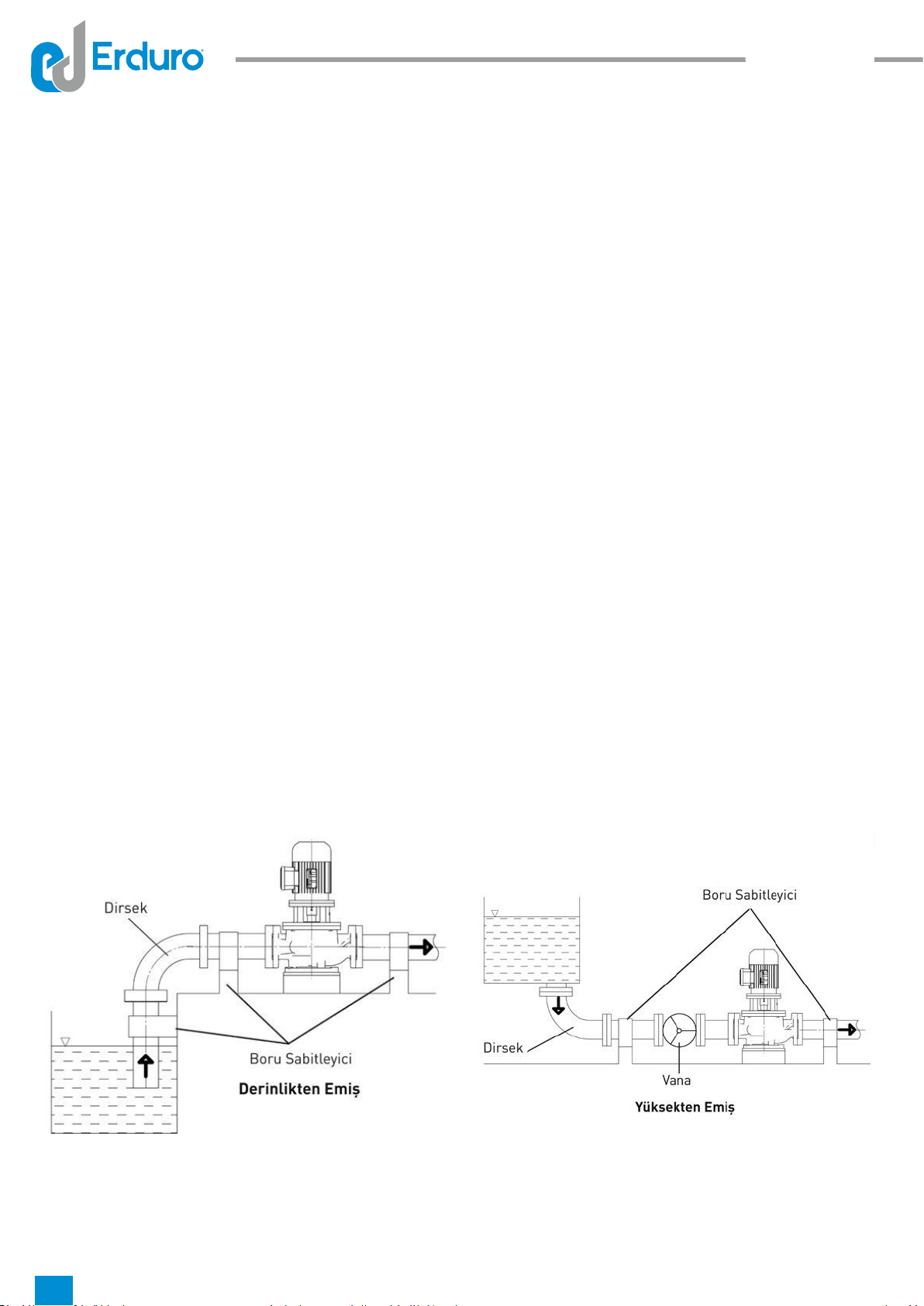
Never use
pumps as a support pont or carrer for a ppe nstallaton.
- Ppe system should be supported from ponts whch are close to pump. Fgure 2.
- Proper expanson equpments should be used for preventng addtonal forces to
pump whch may occur because of expanson n systems whch operate n over
vbrant and hot lquds.
-
Hgh speeds cause decrease n pressure
whch wll cause cavtatons condtons
and excess frcton losses n dscharge ppe.
- Weldng burrs, metal partcles, whch may occur durng ppe equpment producton
sand, and oakum and smlar foregn objects may present nsde pump. Sucton and
dscharge flanges should be closed wth gasket wthout hole for preventng those
materals enter nto pump durng nstallaton. At the end of nstallaton, all ppe parts
should be dsmounted, cleaned and dyed and nstalled agan. If drt retaned s used
at pump sucton lne, t should be removed and cleaned after first few days of
operaton and nstalled agan.
Fgure 2
Fl uid
So lut ion s
7

-
Ppe connectons should be made by flanges. Flanges gaskets should be produced
from sutable materal and should have sutable dmensons. Gaskets whch wll be
used between flanges should be centered for not preventng water flow.
Fgure 3
Sucton and Dscharge Ppe Connectons
- If pump s suppled from a tank whch s hgher than pump, there should be an
solaton valve n sucton ppe whose axs wll be n horzontal poston. Ths valve
should
be completely open whle pump s n operaton and should never be used as
flow rate adjustment valve. (Attenton: Closng valve may cause pump operaton wth
cavtatons. )
-
Sucton ppe should absolutely be mpermeable and should not be arranged to
cause any ar wall. In ths case f a tank s suppled from a tank whch s hgher than
pump, (sucton hgh nstallaton) sucton ppe should be slghtly decreasng sloped
towards pump and suppled from a tank whch s lower than pump, sucton ppe
should be
slghtly ncreasng sloped towards pump.
-
Sharp bends should not be used, sudden drecton changes and cross secton
narrowng should be avoded and sucton ppe should be short as possble for
keepng pump frcton losses as low as possble. If there s need of cross secton
change n horzontal sucton ppe, an ntermedate eccentrc concal part whose flat
type s at upper sde should be used.
-. If pump dschargng heght s more than 10 m or dschargng lne s very long, a
check valve should be placed over dschargng ppe between pump and solaton
valve for protectng pump aganst water mpulses and reverse flows durng stop.
-
A control valve whch s close to pump should be connected for flow rate and
dscharge heght adjustment.
-
If pump dschargng heght s more than 10 m or dschargng lne s very long, a
check valve should be placed over dschargng ppe between pump and solaton
valve for protectng pump aganst water mpulses and reverse flows durng stop.
Fl uid
So lut ion s
8

d1: Sucon Opening Pressure
Meter Connecon
d2: Discharge Opening Pressure
Meter Connecon
By-Pass Valve Connecton
-.
A by-pass valve should be places over dscharge ppe just after pump and before
adjustment valve or outlet flange of pump f there s a case that pump wll operate n
condtons that pump dscharge valve s completely closed(that s wth zero flow rate)
or almost closed (that s wth very small flow rate). If such valve s not used and
pumps operates wth closed valve for a long tme, power whch s provded by motor
wll completely transform nto heat energy and pass nto dscharged lqud. Ths may
cause over heatng and abnormal falures n pump.
ELECTRICAL CONNECTIONS
- Electrcal connectons should be done by authorzed electrcans
Natonal nstructons, regulatons and nstructons of motor manufacturers should be
obeyed.
- Power cables should absolutely be nstalled as not
havng contact wth ppe
nstallaton, pump and motor body.
-
Motor shaft should be rotated by hand before makng electrcal condtons to control
whether t rotates easly.
-
It s recommended to use PTC(Passve Thermal Control-Thermstor) n motors.
However usage of those
depends on customer.
- Electrcal motors should be protected aganst overloadng by crcut breakers and/or
fuses. Crcut breakers and/or fuses should be selected wth respect to full load
values those are wrtten n nameplate on motor.
Fl uid
So lut ion s
9
Fl uid
So lut ion s
-
Compare and control voltage, ampere and frequency values whch are gven n
motor nameplate wth lne values.
-
Motor connecton scheme can be found n motor termnal box or n handbook.
- Motor electrcal connectons should be done accordng to local Electrcal
Regulatons and earthng connecton should absolutely be done.
-
Protecton class of motor body and control system cases n pump should be at least
EN 60529 IP 22. In addton to ths, protecton class of motor bodes and control
systems n pump group should be determned accordng to operatonal and
envronmental condtons.
-
Safety precautons whch are determned n "Safety Instructons" should be appled.
All power connectons should be dsconnected before startng to any work.
-However usage of those depends on customer. If PTC s used ends of those should
be connected to motor termnal box and later should be connected to PTC control
devce n motor control panel.
-
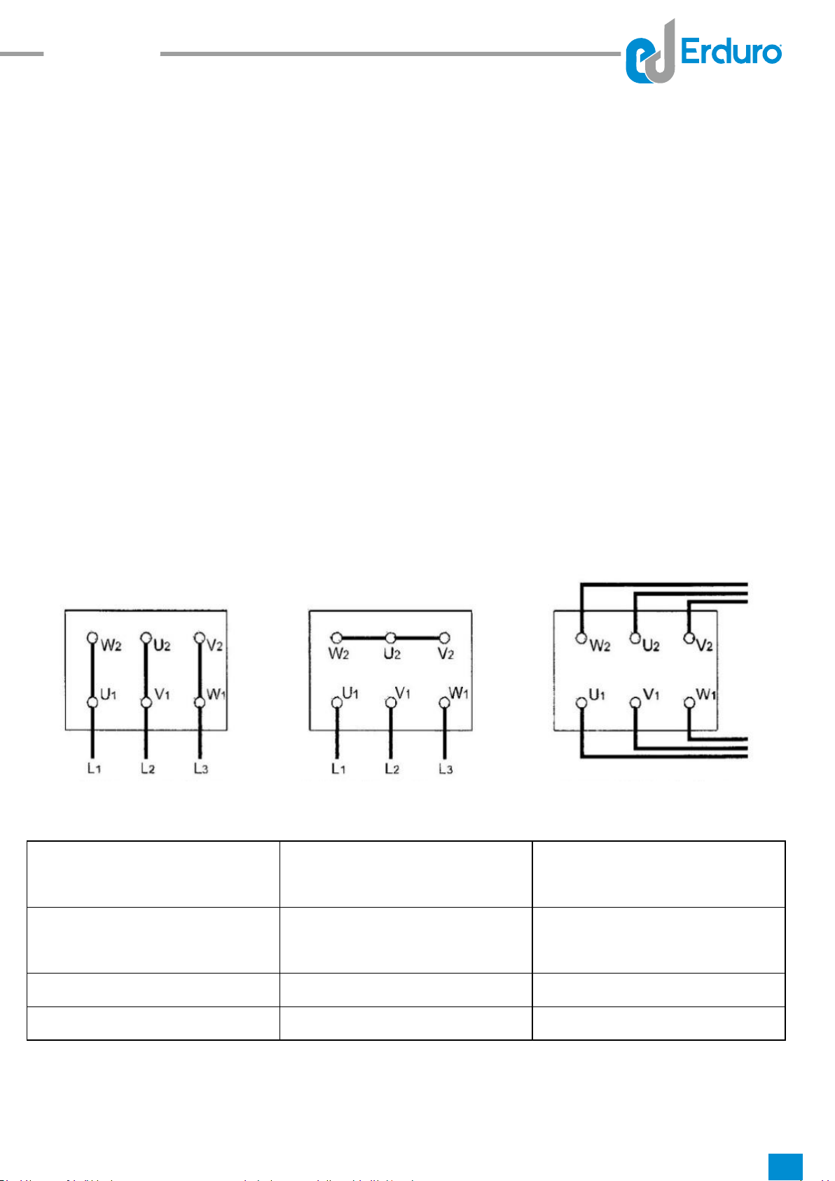
Motor connecton type changes accordng to motor mans power and connecton
type. Necessary connecton types of jumpers n termnal box are dsplayed n Table 1
and Scheme 1a -1b and 1c
Scheme 1a Scheme 1b Scheme 1c
Start Type Motor Power
PN<4kW
Motor Power
PN >4kW
Mans Power
3~400V
Mans Power
3~400V
Drect
Y-connecton (1b) Δ-connecton (1a)
Y/ Δ Star Delta Impossble
Remove Jumpers (1c)
Table 1
10

Fl uid
So lut ion s
Attenton! Transton tme from star to delta should be short n star-delta connected
motors. In case that t s long damages may occur n pump and motors.
Motor Power Y-
Setup tme
<30 kW
>30 kW
<3 seconds
<5 seconds
Table 2
- After all abovementoned operatons are completed, pump rotor should be rotated a
few turns for beng sure that t rotates easly.
-
All safety guards should be nstalled nto ther places. Pump should absolutely be
not operated after ths operaton s made. Ths s oblgatory for safety.
FIRST START
Controls Before Operaton
- If there s bottom back flow water valve n pump wth depth sucton; one of the plugs
n flanges s opened and sucton ppe and pump s filled wth water and ts ar s
taken.
-
Ths case does not cause problem n force feed pumps. Dscharge valve s closed
placement type of pump s consdered and one of the plugs n flanges s opened and
pumps sucton valve s slowly opened and pump s completely filled and ar s
completely removed.
-
If system ncludes vacuum pump, rse of water n sucton pump by means of
vacuum pump and fillng pump s provded. When water reaches the
hghest level
pump s started.
- Pump motor bearngs are "Lfetme Greased " bearngs so they do not need any
control.
-Be sure that there s water n water tank and/or source.
-Be sure that pump and sucton ppe s completely filled wth water.
-ATTENTION! Never let pump run n dry condtons.
11

Determnaton of Rotaton Drecton
- BTKF-I type pumps rotates n clockwse drecton when you look from motor towards
pump. Ths drecton s shown wth an arrow n pump body. Pump s operated for a
short whle and checked whether t rotates n correct drecton. If protecton guard s
unnstalled durng ths operaton, t should mmedately be nstalled after ths
operaton.
Startng Pump
- Check that sucton valve s open and dscharge valve s closed.
- Close the crcut breaker and start the motor.
- Wat motor to reach full speed. (Wat motor to pass delta n motors operaton wth
star-delta)
- Observe the ammeter n panel and slowly open dscharge valve. (If dscharge ppe
s empty n first start, do not open dscharge valve completely and open n controlled
way by controllng that value n ammeter s lower than motor rated values.)
-After valve s completely opened control the value whch s read from ammeter
whether t s same wth the value at operatonal pont. If the ammeter value s less
than operatonal value adjust t by closng the valve. If t s greater check the
nstallaton and statc heght.
ATTENTION: If any of followng problems occur whle pump operates n nomnal
speed; pump should mmedately be stopped and trouble should be elmnated.
1) Pump operates wth over vbraton.
2) Pump and motor connecton bearngs have over temperature.
3) Pressure s not enough.
4) Pump dscharges no water.
5) Flow rate contnuously decreases.
6) Motor operates overloaded
7) Pump operates wth very much nose.
8) Pump does not dscharge sufficent water.
Controls to be Made Whle Pump s Runnng
- Snce pumps have mechancal seal t does not need any mantenance. A few
amount of water may leak from mechancal seal but t s so small that t can not be
notced. If the amount of water comng from mechancal seal ths means that seal
surface s abraded and needs to be replaced. Lfetme of mechancal seal s manly
depends on cleanness of dscharged water.
Fl uid
So lut ion s
12

Fl uid
So lut ion s
- Motor current should sometmes be controlled from ammeter over electrcal panel
whch controls the motor. If current values are more than motor nameplate values
there may be frcton or squeezng n pump. Pump should mmedately be stopped
and mechancal and electrcal controls should be done.
- If there are spare pumps n system, ths type of pumps should be run for a short
whle at least once a week and controlled whether read for operaton. Control wth
auxlary elements f any.
-
Pump should absolutely be run n closed valve condton (zero flow rate) for a long
tme.
-
Pump should operate slent and wthout operaton.
- Bearng temperatures should never exceed ambent temperature (more than 50ºC
It should never exceed 80ºC
- Never operate pump wthout water.
LUBRICATION
- Snce motor bearngs ARE "Lfetme Greases" t does not need any mantenance.
DISMOUNTING PUMP AND REPAIR
ATTENTION!-Always dsconnect the electrcal connectons before start any operaton
over pump and be sure that you have taken necessary precautons to prevent to
operate mstakenly.
DISMOUNTING PUMPS
-
Close the solaton valves n sucton and dscharge
lnes.
-
Unnstall the safety guards.
-Separate the pump group from ppe system by unnstallng the pump sucton and
dscharge flange (and auxlary ppes f any) connectons.
-Separate scroll case from mechancal seal box. Be careful not to gve harm to
mechancal seal whle dong ths operaton.
-Unnstall the mpellor nuts and remove the mpellor wedge. Use rust solvent f
necessary.
-Take the ntermedate bushng.
-Carefully remove the rotatng parts of mechancal seal.
-Separate the mechancal seal box, and carefully remove the fixed elements of
mechancal seal.
-Unnstall the motor carrer.
13

Fl uid
So lut ion s
-Unnstall the pump shaft set screws and rgd couplng shaft bolts dependng on
connecton type.
-Separate pump shaft from motor shaft.
Installaton of Pump
-.
Pump nstallaton operaton s made by reverse order of pump dsmountng
process.
-
Before startng to nstallaton operaton, apply lubrcous materals such as graphte,
slcone or smlar slppery substances over contact surfaces or bolt surfaces. If you
can not find those substances use lqud ol. (drnkng water
pumps excludng)
-
Do not use gaskets whch you had removed. Use new ones havng same
dmensons. Be careful that new gaskets and O-rngs are n same dmensons.
-Place the motor as ts shaft end wll be upper sde and connect the motor carrer to
motor.
- Insert the pump shaft to the motor shaft by sldng.
-Place the seal box over motor carrer.
-Place the fixed elements of mechancal seal nto seal housng.
-Insert the rotatng parts of mechancal seal over pump shaft by sldng and place the
ntermedate bushng.
-Place the mpellor wedge and nsert the mpellor and connect the mpellor nuts.
-Connect the scroll case.
-Place the pump group over frame. Connect the sucton and dscharge ppes (and
auxlary ppes f any.)
-Connect the conductor plate f any.
14

Fl uid
So lut ion s
Fgure 5
Seals
-BTKF-I type pumps are always produced wth mechancal seal.
-Water leakage does not occur n a mechancal seal whch properly works. Generally
f there s not any vsble water leakage seals do not need mantenance. Besdes ths
mpermeablty of mechancal seals should regularly be controlled.
-Absolutely obey the nstructons of manufacturers where mechancal seals are used.
never operate the seal n dry condtons.
15

Fgure 6
1) Impellor
2) Carrer Foot
3) Scroll Case
4) Mechancal Seal
5) Dscharge Openng
6) Splash rubber
7) Pump Shaft
8) Motor
9) Sucton Openng
CROSS SECTION DRAWINGS
Fl uid
So lut ion s
16

Fl uid
So lut ion s
Table 3
1
There s ar n lqud Swrls occur snce depth of submerson ppe s
not enough and there fore ar can not be
absorbed. Control the lqud level n sucton tank
and ncrease the depth of bottom/sucton ppe
back water valve.
2
Ar pocket n sucton ppe Control the slope of sucton ppe and whether
there are sutable places for formaton of ar
pockets, f any make necessary correctons.
3
There may be ar n pump
and/or sucton lne
Fll pump or sucton ppe completely wth lqud
and repeat the start process
4
Ar s not
absorbed from
seal, sucton ppe, or
connectons. Pump absorbs
lqud whch s mxed wth ar
Control all connectons n sucton ppe. Check
seals. If necessary feed seals wth pressurzed
water. Check the submerson depth of sucton
ppe pr deep back water valve and ncrease
submerson depth f necessary.
FAILURES POSSIBLE REASONS
Started pumps never dscharges water 3-6-8-12-11-14
Flow rate decreases or no water s dscharged 4-2-7-15
Motor s overloadng
9-10-16-22
Bearngs have over temperature 17
There s vbraton n pump
13-18-21-19
Nose level s hgh
1-5-20
17
SPARE PARTS
- ERDURO warrants to provde the spare parts for BTKF-I Seres pumps for 5(five)
years begnnng from producton date. You can always easly obtan the spare parts
you need.
- In spare parts order, t wll be sufficent for you to nform the followng values whch
are wrtten n pump nameplate.
Pump Type : BTKF-I 40/200
Motor Power(P) and Revoluton(n) :5,5 kW - 2900 d/d
Producton Year and Seral No : 12/2011 - 201112-001
Flow rate(Q) and Manometrc Heght (Hm): 15 m³/h - 44 mSS
REASONS FOR FAILURES AND TROUBLE SHOOTING
type pumps, possble reasons
(Table 3 ) and trouble shootng methods (Table 4 ) are gven.
ATTENTION! Control the accuracy of all measurement gauges before startng to
elmnate the falure operaton.
In ths chapter falures which can be seen BTKF-I

Fl uid
So lut ion s
5
Pump operates wth
cavtatons
NPSH of plant s very low. Check the water level
n sucton tank. Check whether there are over
frcton losses n sucton lne. Check whether
solaton valve n sucton lne s completely open.
If necessary place the pump n low levels and
ncrease the load of pump at sucton sde
6Sucton depth s very much
If there s no obstacle whch may cause cloggng
control the frcton losses of sucton lne. If
necessary use a sucton ppe havng larger
dameter. If statc sucton depth s too much you
should rase the heght of water level n sucton
tank or pump should be places n lower levels.
7
Increase n dscharge heght Check whether valves are completely open. Check
whether there s an obstacle whch may cause
cloggng n dscharge ppe.
8
Pumps dscharge heght s
nsufficent
Actual dscharge heght of plant s hgher than gven
values. Check the total statc heght and frcton
losses of dscharge ppe. Usng ppes havng
greater dameter may be soluton. Check whether
valves are completely opened.
9
Pump s operatng at lower
dscharge heght
Dscharge heght of plant s lower than gven
values. Lathe the mpellor dameter accordng to
manufacturer suggestons
10
Speed very much Decrease the motor revoluton f possble or Lathe
the mpellor dameter accordng to manufacturer
suggestons
11
Pump rotates reverse Check rotaton drecton of motor whether t s
same wth the drecton whch s ndcated n pump
body or nameplate
12
Impellor partally clogged Clean the mpellor
13 Impellor, check valve or filter
clogged
Clean Impellor, check valve or filter
14 Impellor, partally filter clogged
Clean Impellor, or filter
15 Mechancal frcton n pump Check whether there are any obstacle or bend n
pump rotor
16 Flow rate s less than pumps
necessary flow rate
Increase the flow rate, use by pass valve or lne f
necessary
17 Worn or malfunctoned
mpellor
Replace the mpellor
18 Imbalanced rotatng parts Adjust the balance of rotatng parts
19
Pump operates out of ts
operaton regon
Check the operatonal regon values
20
Shaft s bend Check the shaft and replace f necessary
21
Motor Falure
Check the motor,. Motor s not sutable for ts ar
condtonng poston
Table 4
18

Fl uid
So lut ion s
INSTALLATION TYPES
Fgure 7
19

Fl uid
So lut ion s
SCREW DIAMETER
MAXIMUM TIGHTENING MOMENT(Nm)
CLASS PROPERTIES
8.8 10.9
M4 3 4,4
M5 5,9 8,7
M6
10 15
M8
25 36
M10 49 72
M12
85 125
M14
135
200
M16
210
310
M18 300 430
M20
425
610
M22
580
820
M24
730
1050
M27
1100
1550
M30
1450
2100
M33
1970
2770
M36 2530 3560
TIGHTENING MOMENT
20
This manual suits for next models
1
Table of contents
Popular Water Pump manuals by other brands


Zoeller
Zoeller 7008 owner's manual

Elmo Rietschle
Elmo Rietschle C-KLR 140 Original operating instructions

Wilo
Wilo Sub TWU 3-HS Series Installation and operating instructions

BUSCH
BUSCH DOLPHIN LA 0053-1111 A Installation and operating instructions

Pentair
Pentair SHURFLO PIRANHA 375-116-10 quick guide

FUXTEC
FUXTEC FX-WP152 Original user manual